Ultrafine Spheroidal Graphite Iron Castings
キーワード:
spheroidal graphite iron,
gravity die casting,
free nitrogen,
ultrafine nodule,
chill free,
as-cast
2019 年 60 巻 1 号 p. 41-48
詳細
2019 年 60 巻 1 号 p. 41-48
Gravity die casting of spheroidal graphite iron had been attempted controlling free nitrogen during preparing base molten iron, magnesium treatment, inoculation and pouring. In this study, the actual CO/SiO2 reaction temperature of base molten irons was surveyed and magnesium treatment was conducted at that temperature. The mold was made of steel and the cavity size was thickness of 5.4 mm and diameter of 35 mm. As the results, ultrafine graphite nodules were obtained without chill in as-cast condition. They were average diameter of 7 µm and density count of over 3,000/mm2. Knuckle for automobile was also cast taking the same procedure. Knuckle had no meager defect like shrinkage, chill etc. in as-cast conditions. The possibility of no chill has become extremely higher than former study.
The product quantity of spheroidal graphite iron castings has been grew like graph rising to the right in last four decades.1) It has been only one in the ferrous materials (Fig. 1). If spheroidal graphite can be controlled an extremely small, the mechanical properties such as tensile, fatigue limit strength and fracture toughness will be expected higher values than now.2) Furthermore, new physical property such as high thermal conductivity may be expected because graphite nodule spacing is much closer than that of present spheroidal graphite irons. As the results, new usage will be found, and the product quantity will have to be increased more.
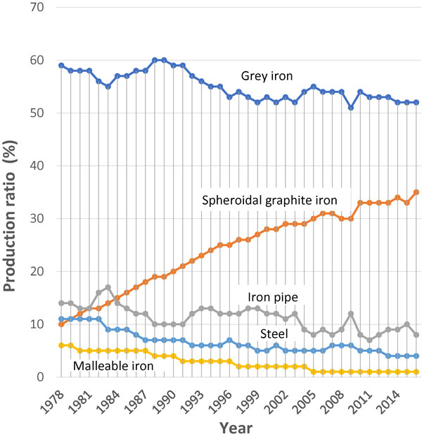
Production ratio of ferrous castings for last four decades in Japan.
In conventional way, spheroidal graphite diameter SGD of 15 µm and the number density SGN of 900/mm2 have been the limitation without chill formation in as-cast condition of thin wall sand castings.3) To get smaller size and larger number of graphite nodule, higher solidification speed is required than sand mold, avoiding chill formation. Many researchers4–10) had tried permanent mold casting for spheroidal graphite iron to not only develop a new material but also create a future model of iron foundry. However, there had been almost no foundry who could succeed chill free castings in as-cast condition in practice although some researcheres7–9) had been able to succeed it in laboratory.
According to author’s study,11) it has been known that free nitrogen NF and chill depth have good relationship in 30ton arc furnace melting in practice. It has been considered that nitrogen atom can partially substitutes carbon atom in cementite crystal structure (Fe3C) and enhances chill formation when the solidification rate is fast enough. Such cementite might be the form of Fe3(C·N). In the recent study,12) the time-temperature schedule was introduced as one of countermeasures for chill formation. In the schedule, equilibrium CO/SiO2 reaction critical temperature TEC was adopted. However, it should be actual CO/SiO2 reaction critical temperature TAC to get stable results because there may be no equilibrium condition in foundry at all. So, the schedule was not enough yet. Furthermore, magnesium treatment accompanied with intensive reaction must be more considered.
In this study, gravity die casting was attempted to get ultrafine graphite nodule under stable conditions in laboratory and to apply the technology in practice.
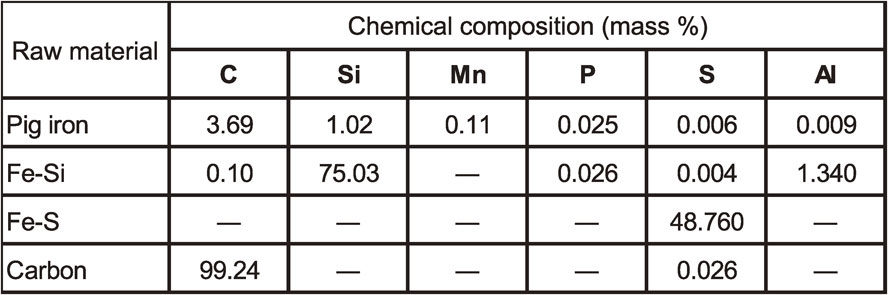
The raw materials for gravity die castings shown in Table 1 were melted using a 30 kg high frequency induction furnace. Melting, magnesium treatment, inoculation, and pouring were conducted using the time-temperature schedule shown in Fig. 2. The schedule had been already reported to countermeasure.12) After being melted, the base molten iron was super-heated at over 1,500°C and slowly cooled down to TEC without electric power. During cooling down, chill sample was taken with general permanent mold and chemical composition was analyzed using spectrometer. TEC was calculated according to the carbon and silicon contents in the base molten iron, according to eq. (1) and (2).13)
| \begin{equation} \mathrm{T}_{\text{EC}}\ ({}^{\circ}\text{C}) = \mathrm{T}_{\text{K}} - 273 \end{equation} | (1) |
| \begin{equation} \mathrm{T}_{\text{K}} = -27{,}486/(\log[\text{Si/C$^{2}$}] - 15.47) \end{equation} | (2) |
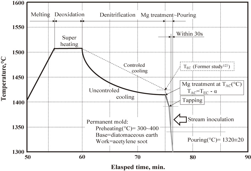
Time-temperature schedule for melting, treatment, and pouring.
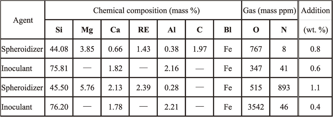
Around calculated TEC, the starting temperature of SiO2-film formation on the surface of base molten iron, so-called TAC was measured using K-type thermocouple. During slow cooling, denitrification was expected by solution difference in temperature decrease.8) Magnesium treatment was conducted at TAC using a plunger in the furnace (Fig. 3). Stream inoculation was conducted in alumina-silica ceramic ladle after magnesium treatment (Fig. 3). Those chemical compositions and amount of treatments are shown in Table 2. To make treatment reaction mild, alloy should have lower magnesium content as possible because the alloy contained high magnesium cause intense reaction and promote chill.9)
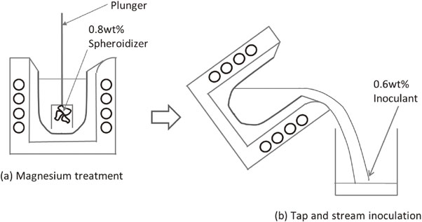
Procedure of magnesium treatment and inoculation.
The magnesium-treated and inoculated molten iron was poured into the preheated die using an alumina-silica ceramic spoon within 30 s after inoculation. The pouring temperature aimed was 1320 ± 20°C. The shape and dimensions of the die12) is shown in Fig. 4. This die was originally designed and manufactured to take chill samples for accurate spectrometry analysis in general foundry operations. The experimental die was coated with two layers. One was the base coating which was directly coated on the die. It was water-based diatomite. The thickness was about 0.4 mm. Another was the work coating on the base and was acetylene soot. The thickness was about 0.2 mm. Coated die was preheated to 350°C in an electric furnace. The as-cast sample castings were taken out at temperature below 550°C. Chill samples for spectrometer were taken by pouring the same liquid iron into general die. The chemical composition was analyzed using spectrometry. This spectrometry has a pulse-height distribution analysis (PDA) system and state analysis of magnesium could be conducted. The analysis samples were also analyzed on carbon and sulfur contents using the infrared absorption method (CS-LS600, Leco Corp.).
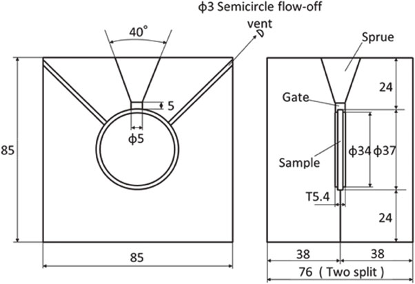
Shape and dimensions of the medium-carbon steel gravity die (unit: mm).12)
A sample casting was cut in the vertical section from gate to bottom. It was buried in resin and the microstructures were observed using optical microscopy. SGS was measured and SGN were counted through the microstructural photograph by hand.
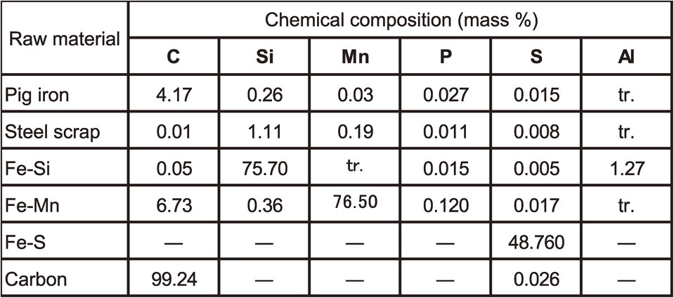
Three different kind of sand mold castings were poured. Their microstructures were compared with die castings. The first was wall thickness of 6.5 mm and weight of 130 kg which would be able to show the maximum graphite nodule count in conventional technology. The second was 25 mm Y type block which was described in JIS G 5502. The microstructure was used as standard. The third was 100 mm Y type block as representative microstructure of heavy section castings. The raw materials for sand mold castings shown in Table 3 were melted using 10ton low frequency induction furnace. The same alloys shown in Table 2 were used for liquid treatment.
To consider the possibility of chill free gravity die casting in spheroidal graphite iron in practice, a steering knuckle for automobile was also poured taking the same procedure as described above. The quality was surveyed about surface, shrinkage, and microstructure. The riserless casting design is shown in Fig. 5. A gating system was not designed but the sprue was connected directly to the knuckle body.
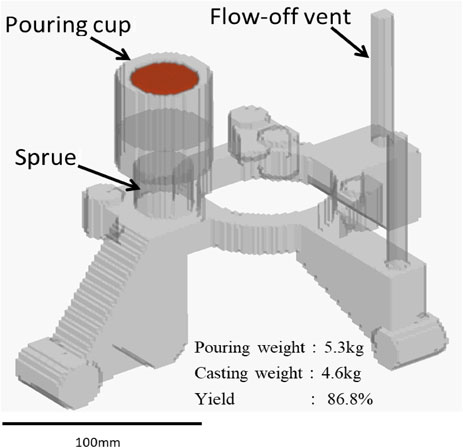
Cast design of steering knuckle for automobile.
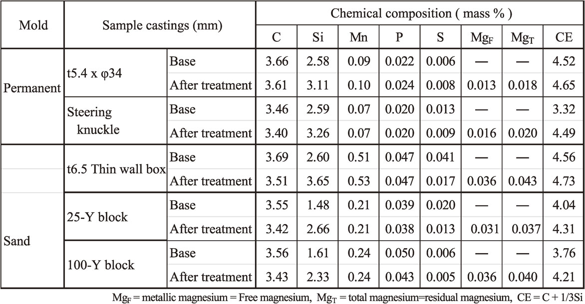
The chemical compositions of the molten irons are shown in Table 4. TEC of the base molten iron was calculated as 1425°C by eq. (1) and (2). After the base molten iron was super-heated to 1540°C, it was slowly cooled down in the furnace without electric power. SiO2 film began to form at about 1415°C, and then, magnesium treatment was conducted at 1415°C using plunger in the furnace. The difference between TEC and TAC was about 15°C. Soon after the magnesium reaction finished, the molten iron was tapped into ceramic ladle. Stream inoculation was conducted during tapping. The treated molten iron was poured into the preheated die at 1340°C using the ceramic spoon. The time elapsed from inoculation to pouring was 23 s. These conditions are shown in Table 5 compering with other heats. Polished cross section of sample casting is shown in Fig. 6. A depression on the side wall and inside shrinkages were observed as shown in Fig. 6(a) when sample castings were no chill and full graphite structure. When some conditions were wrong, chill macrostructure was observed as shown in Fig. 6(b). The chemical composition of the magnesium-treated and inoculated molten irons is also shown in Table 4. Carbon and sulfur values in analysis samples after these treatments showed less accuracy in spectrometry analysis. According to the former study,12) it was considered that graphite precipitation was rather dominant although molten iron was poured into general die for full chill. Therefore, the analysis results of the infrared absorption method were adopted for them in Table 4. The results of state analysis are also shown in Table 4. MgF is metallic state of magnesium.14) MgT is total magnesium14) and is called as residual magnesium in conventional foundry operations.

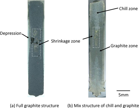
Polished cross-sectional surfaces of as-cast sample castings.
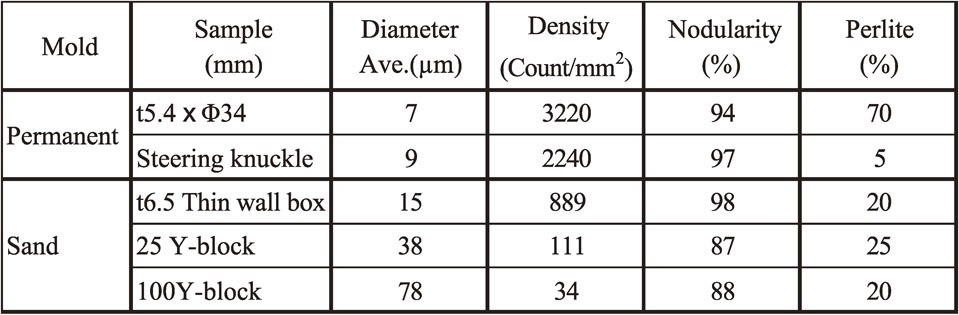
Full spheroidal graphite structure was observed in Die casting sample. The representative microstructure is shown in Fig. 7. Most of spheroidal graphite was ultrafine (Fig. 7(a)). The range of SGD was 4∼9 µm and the average SGD was 7 µm. Larger spheroidal graphite nodules exist but their diameters remain at about 15 µm. These were assumed to be hypereutectic graphite nodules that formed during pouring. SGN was 3220 count/mm2. Fine shrinkage cavities were found beneath the depression on the side wall of the sample casting. This might be caused by the narrow gate. Since magnesium treatment was conducted at TAC, success rate of full graphite structure could be much better than that of former study.12) To compare conventional sand castings, three kinds of the microstructures were also shown in Fig. 7(b)–(d). This comparison is simple and easy to understand. The microanalytical results are shown in Table 6. The microstructure shown in Fig. 7(b) is close to the conventional limit of nodule density without chill. Chill (ledeburite) was only observed in the Φ3.0 mm semicircle flow-off vent. The microstructure is shown in Fig. 8. SGN was 3620 count/mm2, the highest count from the sample. However, about 25 area% of ledeburite is present among old eutectic cells.
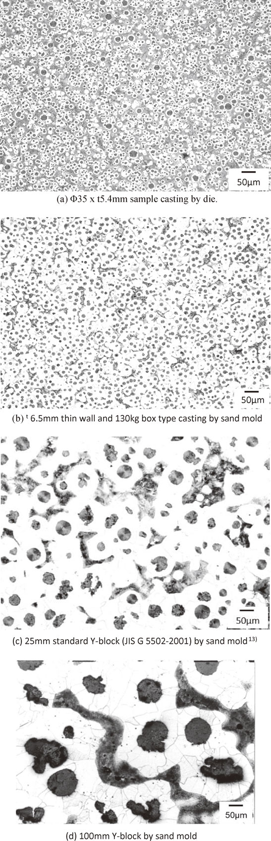
Microstructures of die and sand mold castings.
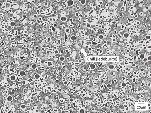
Microstructure of Φ3 semicircle flow-off vent for sample casting (3 vol% nital etch). SGN: 3620 count/mm2.
The steering knuckle was poured into preheated die at 1326°C. The time elapsed between inoculation and pouring was 38 s. The filling time was 6 s. The knuckle was taken out from the mold at a temperature below 500°C. The as-cast appearance of the steering knuckle is shown in Fig. 9(a). The surface appears good without any visible magnesium dross, flow marks, cold shot, or other defects. The knuckle was cut at the position A, B, and C in Fig. 9(a) and the sectional surfaces were visually observed. The results are shown in Fig. 9(b)–(d). No shrinkage was observed in any sections. However, gas hole was observed in section C. The nodule number density reached over 2240 count/mm2. As an example, the microstructure of section B in the steering knuckle is shown in Fig. 10. This count was over 10 times greater than that found in similar size of sand mold steering knuckles.15) No chill was observed. The microanalytical results are shown in Table 6.
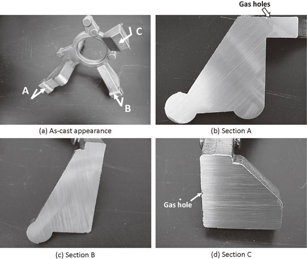
Quality of surface and cross-sections in steering knuckle by gravity die casting.
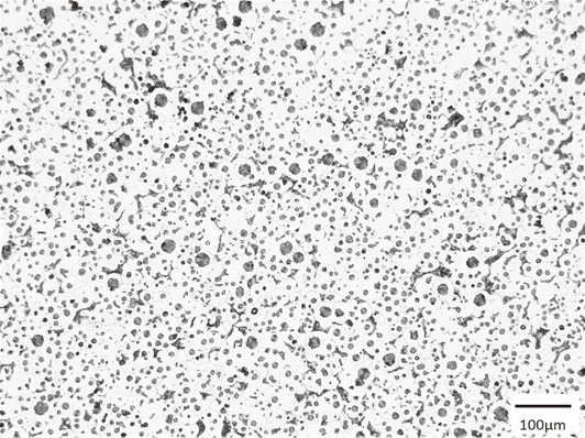
Microstructure of surface layer at section B in steering knuckle, as shown in Fig. 9(a) (3 vol% natal etch).
When wall thickness becomes thinner and/or cooling rate become faster, SGD generally becomes smaller and SGN increases. However, ledeburite structure begins to form when the cooling rate is too fast. According to H. Horie,3) the critical count of SGN without any ledeburite structure is approximately 900 count/mm2 giving eq. (3):
| \begin{equation} \mathrm{SG}_{\text{N}} = 0.58\mathrm{R}^{2} + 19.07\mathrm{R} + 1.01 \end{equation} | (3) |
| \begin{equation*} \mathrm{R} = \text{Cooling rate}\ ({}^{\circ}\text{C}/\text{s}) \end{equation*} |
Alloying elements such as manganese and chromium are generally known to promote chill formation tendencies.16) These elements are also known to increase nitrogen resolution in molten iron.17) On the contrary, carbon, silicon and phosphorus decrease increase nitrogen resolution in molten iron and inhibit chill formation.16,17) This suggests that they may promote chill by increasing NF levels in molten iron. Such elements may promote chill as the atoms substituting for iron atoms in Fe3C because they are close to in atomic size. Furthermore, the electronegativity of such substitution elements with carbon is greater than that between iron and carbon.8) The same is true for nitrogen and oxygen atoms regarding substitution. NF and chill are related by the substitutional ability of nitrogen atoms for carbon atoms in Fe3C, which could promote chill. However, free oxygen (OF) has less possibility to promote chill according to the results of the previous study.11) Sulfur is effective to inhibit nitrogen absorption and chill formation,18) but it inhibits graphite spheroidization.
Magnesium vapors at about 1100°C in atmospheric pressure. The magnesium atom has almost no solubility in molten iron. Therefore, vapored magnesium gas can exist as gas bubbles in molten iron. The size of magnesium gas bubbles is calculated by eq. (4)19) and (5). The calculated size of magnesium gas bubbles is shown in Table 6. Spheroidal graphite nodule shown in Fig. 10 in this study had the average size of 7 µm. This is close to calculated size of magnesium gas bubbles in molten iron when the magnesium alloy is treated at 1400–1450°C (Table 7).20) According to Table 7, finer magnesium gas bubbles would be able to be possible in shallower molten depth and/or higher temperature than this study, if there were other way to have chill free in as-cast condition.
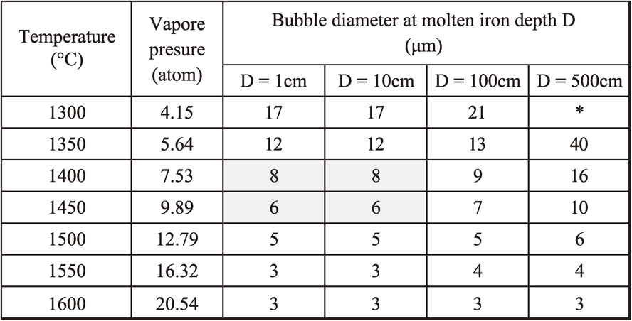
Vapor pressure of magnesium (atm): PMg
| \begin{equation} \text{Log}\,\mathrm{P}_{\text{Mg}} = 4.958 - (1.229\times 104)/\mathrm{T} \end{equation} | (4) |
| \begin{equation} \mathrm{P}_{\text{Mg}} = \mathrm{P}_{\text{a}} + \rho\text{gH} + 4\gamma/\mathrm{D} \end{equation} | (5) |
| \begin{equation*} \mathrm{D} = 4\gamma/(\mathrm{P}_{\text{Mg}} - \mathrm{P}_{\text{a}} - \rho\text{gH}) \end{equation*} |
P. Kainzinger, et al.21) had concluded that fatigue limit strength improves when the density count of spheroidal graphite become smaller in sand mold casting. Since the range of density count was 20∼250 count/mm2 in their study, the great improvement of fatigue limit strength may be expected density count like this study. Furthermore, higher thermal conductivity than that of conventional spheroidal graphite iron because the mutual distance among nodules are much closer than that of conventional one.
Besides nodule size and density count, full graphite structure with no chill in knuckle casting in as-cast condition must be trustworthy. There were some laboratories7,9,22,23) who had succeeded permanent mold spheroidal graphite iron castings without heat treatment, but there was almost no report for applying it in foundry practice yet. There are some foundries5,6,24) who have taken permanent mold casting of spheroidal graphite iron. However, they have had graphitization heat treatment of ledeburite structure. It has been known that graphitization heat treatment of chill irons contained magnesium completes in a short time such as a quarter hour. This is much shorter than that of malleable irons. But, there is a possibility to form an unfavorable microstructure such as low nodularity, nodule line-up like discontinuous crack, etc.10) These unfavorable microstructures depend on the distribution of magnesium voids. Magnesium voids exist the site between cementite and austenite in needle like ledeburite.19) The sphere shape of magnesium gas bubbles becomes irregular by ledeburite when molten iron solidifies. Tempered graphite precipitates in magnesium voids.7) Graphite line-up may affair the mechanical properties, especially fatigue limit strength.
It was confirmed that the NF theory11,12,25) for chill formation and the site theory26–29) for graphite spheroidization could be used practically to get ultrafine spheroidal graphite iron casting with no chill in as cast condition. As the issues in next study, NF shall be analyzed as the same procedure as former study.11)
Gravity die casting of spheroidal graphite iron was attempted controlling NF. The following results were concluded: