Abstract
Here we show an electrophoretic deposition process for a uniform coating of glass substrate surface with fluorescent silicon nanocrystals (SiNCs). The NCs with ∼35% of photoluminescence quantum yields (PLQYs) were synthesized by thermal disproportionation of hydrogen silsesquioxane, followed by hydrosilylation of 1-decence. Next, the hollow-silica particles that are crammed of the decane-terminated NCs were prepared by taking advantage of a vacuum impregnation process. The PL spectra were measured as a function of temperature for films of NCs before and after silica encapsulation. It was observed that a rapid decrease of PL intensity with elevated temperature for the hydrogen-terminated NCs whereas the silica capsule suppresses a thermal quenching to give PL stability at high temperature. The presence of a silica capsule also allows electrophoretic deposition of the NCs to the surface of an ITO glass substrate.
This Paper was Originally Published in Japanese in J. Jpn. Soc. Powder Powder Metallurgy 65 (2018) 108–113.
1. Introduction
By taking an advantage of the quantum confinement effect that occurs upon reducing the size of inorganic crystals to the nanoscale, a broad range of applications such as electricity generation,1) artificial photochemical synthesis,2) energy storage,3) displays,4) medicine and drug delivery5,6) is expected to be developed. Organochemical modifications of the surface of nanocrystals (NCs) produce a transparent colored colloidal ink. The colloidal ink is compatible with the existing printing technologies such as printable electronics.7,8) Unlike epitaxial films, the colloidal ink has, in theory, no constraints on the substrates on which it is deposited. This is a characteristic advantage of colloidal ink.9)
However, for device fabrication, the primary choices for thin film deposition are dominated by spin coating or drop casting, which allows simpler and cheaper production of a thin film of NCs but is unsuitable to control the packing density of NCs comprising the film or the distance between NCs within the film. In contrast, self-assembly approaches, which include the Langmuir-Blodgett and dip coating methods, are suitable to precisely control NCs comprising a thin film by, for instance, enabling the formation of the superlattice structure,10,11) but they take an inconceivably long time to fabricate a thick film.
Our research has thus far focused on electrophoretic deposition (EPD) as a deposition process for a thin and a thick film of NCs. EPD is a colloidal processing method. Upon applying an electric field to a suspension of powdered raw materials, EPD makes charged particles migrate electrophoretically towards the electrode with the opposite polarity and then they are deposited on the substrate to form a deposition film. It involves solidification in the film deposition. EPD offers a convenient method to fabricate a fine and elaborate a thin film from colloidal solutions.12)
Silicon (Si) is an environmentally friendly semiconductor. It is highly recyclable and has been used as a fundamental material of semiconductor integrated circuits, supporting the modern highly sophisticated information society. However, since Si has an indirect transition-type band structure, its photoluminescence quantum yield (PLQY) is extremely low.13) The emission of visible light from the Si nanostructure reported in 1990–1992 showed promise of a new frontier of optical properties in material science.14,15)
Later, a surface control technique that could increase the PLQY was elucidated, which led to the research and development of Si applications as light emitting device components.16–18) Holmes et al. for the first time fabricated a light emitting diode with colloidal Si NCs embedded in its light emitting layer and accomplished a high external quantum efficiency (EQE > 8%). Lemmer et al. reported the red and orange light emitting diodes (LEDs) by taking advantage of the QC effect generated in the Si NCs.20) Ghosh et al. reported the concept of the additivity of spectra using the light absorption and emission properties, which are characteristic of Si NCs, to achieve white light emission.21) As device research advances and broader applications of this technology are demonstrated, not only improved deposition processes of a thin film of NCs but also suppression of oxidation22) and enhanced heat resistance will be necessary.
In this present study, we develop a deposition process for a thin or thick film of inorganic NCs using the aforementioned EPD process. Si NCs are used as a model particle. To increase the PLQY, Si NCs were terminated with an alkyl group.16) Since the surface of the methyl group remains electrically neutral even upon applying an electric field, we cannot deposit a film of NCs over the substrate surface. To solve this problem, we encapsulated alkyl-terminated Si NCs into hollow silica particles. To investigate the effect of heat resistance due to the formation of this protective shell, we conducted in-situ PL measurements while changing the sample temperature.
2. Experimental Procedure
2.1 Preparation of silicon nanocrystals (ncSi)
In a typical synthesis, 5 mL of TES (6.0 g, 45 mmol) was added to an eggplant-shaped flask equipped with a magnetic stir bar and stirred in Ar atmosphere using standard Schlenk techniques. HCl solution (water:HCl = 3:1) (1.6 mL) adjusted at pH 2 was added drop wise slowly to the TES placed at the bottom of flask. After some time xerosol was formed and then the gel was dried in vacuum for overnight. According to the eq. (1), the dried gel was hydrogen silsesquioxane, i.e., (HSiO1.5)n, as described later.
| \begin{equation}
\text{4HSi(OCH$_{2}$CH$_{3}$)$_{3}$} + \text{6H$_{2}$O} \rightarrow \text{4HSiO$_{1.5}$} + \text{12CH$_{3}$CH$_{2}$OH}
\end{equation}
| (1) |
The HSiO
1.5 powder was then heated at 1100°C for 1.5 h in argon atmosphere containing 5 vol%-hydrogen (5%/95% H
2/Ar) with a conventional muffle furnace. The white powder of HSiO
1.5 turned
metallic black during heating. According to the
eq. (2), the heated HSiO
1.5 was ncSi-contained SiO
2 powder.
| \begin{equation}
\text{4HSiO$_{1.5}$} \rightarrow \text{ncSi} + \text{3SiO$_{2}$} + \text{2H$_{2}$}
\end{equation}
| (2) |
200 mg of the fine powder was mixed with 5 mL of ethanol and 5 mL of HF (48%). Then, the mixture was stirred for 1 h to achieve the acidic etching of SiO
2 matrix and the gradual decrease in size of core Si. The hydride-terminated ncSi (ncSi:H) was centrifuged at a rotation speed of 15,000 rpm, washed two times with ethanol and acetonitrile. Dichloromethane was used for collection.
2.2 Preparation of Decane-terminated Si NCs (ncSi-De)
Si can covalently bond to carbon, nitrogen and oxygen which are major constituent elements. Therefore, there are various reaction routes for surface modification of Si NCs.23) A covalent carbon-silicon linkage efficiently works to enhance a PLQY.16,17) Hydrosilylation of 1-alkenes is the most conventional method for this purpose. In this work, 1-decence was used for the reaction. After the centrifugation, the power was transferred into another two-neck flask connected with a condenser on a schlenk line. Dichloromethane remained was completely removed from the powder in vacuo. A 20 mL 1-decene was added to the flask in Ar atmosphere. The hydrosilylation of 1-decene on the ncSi:H was carried out at 170°C in Ar atmosphere. The transparent and brownish-red color solution was obtained after 5 min, and the solution was cooled down to room-temperature. The unreacted 1-decene was removed by evaporator. Finally, the chloroform solution of the ncSi-De was purified by gel permeation chromatography (GPC). The GPC-treated ncSi-De could be redispersed in chloroform.
2.3 Preparation of ncSi-De encapsulated in silica (ncSi-De/SiO2)
A hollow silica particles (SiliNax, SP-PN, Nittetsu Mining Co., Ltd) was used to encapsulate the ncSi-De. The predefined amount of SiO2 particles was added in the chloroform solution. The solution was left under vacuum conditions for a while, and returned to ambient pressure with Ar gas. The SiO2 particles were centrifuged and washed with chloroform to remove the ncSi-De adsorbed on the surface of the particles. Then the particle was added into the chloroform solution. By repeating this process, we obtained ncSi-De/SiO2 particles.
2.4 Preparation of the ncSi-De/SiO2 film by EPD process
Colloidal suspension for the EPD was prepared by 30 min sonication of 20 mL isopropyl alcohol containing 400 µL glycerin and small amount of 0.1 M magnesium nitrate hexahydrate, followed by dispersion of 50 mg ncSi-De/SiO2. ITO-coated glass substrate (10 Ω/cm2, model IN-100, Furuuchi Chemical Corp., Tokyo, Japan) adapted for cathode was connected with SUS substrate working as an anode. The working distance between electrodes was 10 mm. The EPD was performed for 1 min at 10 V. We observed a rough film of ncSi-De/SiO2 particles when the applied voltage for EPD was 5 V. Also ITO film got a damage at 20 V. The 1 min for EPD duration was proper for the present case. After the EPD, the film was dried for PL measurement.
3. Results and Discussions
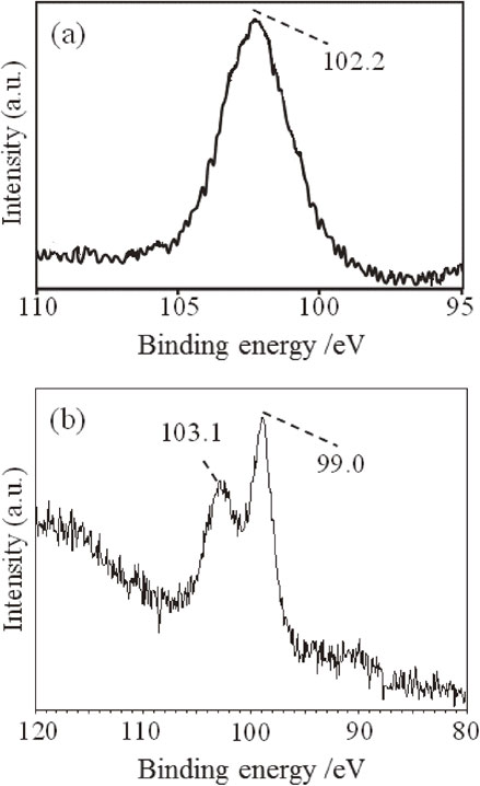
Figure 1, which presents the XPS spectra of TES-derived hydrolysis product before and after heat treatment, shows the oxidation state of Si. Since the oxidation state of Si in the hydrolysis product was trivalent (Si2p peaking at 102.3 eV) as shown in Fig. 1(a), we confirmed that the powder is hydrogen silsesquioxane. Heating to 1100°C changed the oxidation state of Si into zero-valence (Si2p peaking at 99 eV for metallic Si) and tetravalent (Si2p peaking at 103 eV), as shown in Fig. 1(b).
The size of each crystallite calculated from the X-ray powder diffraction pattern (XRPD) using the Scherrer equation was compared before and after the HF etching treatment. The comparison showed almost no change in size. Hence, we considered that the powder produced in thermal disproportionation of hydrogen silsesquioxane is composed of SiO2, where single nanosized ncSi is dispersed.
The size of ncSi that nucleates and grows in the SiO2 matrix depends almost exclusively on the reaction temperature for thermal disproportionation and the dopants.25,26) To prepare fluorescent NCs, the reaction temperature is controlled in between 1000–1200°C. Also, the use of inert gas atmosphere containing 3–5 vol% hydrogen for the thermal disproportionation reaction enhances the nucleation, favoring the synthesis of visible-light emitting NCs.16) In contrast, the reaction carried out in a vacuum or under an Ar atmosphere tended to grow crystallites greater than those grown in the H2–Ar system, favoring the synthesis of near-infrared light emitting NCs.25) For hydrofluoric etching to terminate the surface of NCs with hydrogen atoms followed by liberation of the hydrogenated NCs (ncSi:H) from the oxide matrix, the thermally disproportionated product (i.e., ncSi/SiO2) was stirred in an etching solution containing hydrogen fluoride of 48 vol%. In the experiment, the stirring time was set to one hour to avoid contamination of byproducts of the reaction.25)
Figure 2(a) shows a scheme for hydrosilylation of 1-decene. Generally, the higher the reaction temperature, the higher the molecular packing density of decane monolayers; preferably, the temperature for the reaction is controlled at 170°C or higher.18) Since the ncSi:H is insoluble in 1-decene, the solution of 1-decene before the reaction was turbid but as hydrosilylation proceeded, the transparency of solution increased gradually. This is because each NC surface is terminated with a decane molecule in hydrosilylation, which makes ncSi:H soluble in 1-decene. In this experiment, the reaction was halt when the color of solution became a transparent reddish brown as shown in Fig. 2(b). Since decane-terminated ncSi (ncSi-De) is terminated with a methyl group, the surface of NCs is not polarized, which results in a high degree of dispersion of them in unreacted 1-decene. PL was observed upon irradiating the solution with 365-nm ultraviolet light. PL corresponded to a fluorescent wavelength that depended on the size of ncSi. As shown in Fig. 2(c), the solution exhibited a fluorescent red color with a high PL intensity. The PLQY was 32%. The average diameter of ncSi dispersed in the solution shown in Fig. 2(c) was estimated from the TEM observation to be 2.2 nm, which agrees well with the previous study in literature.16)
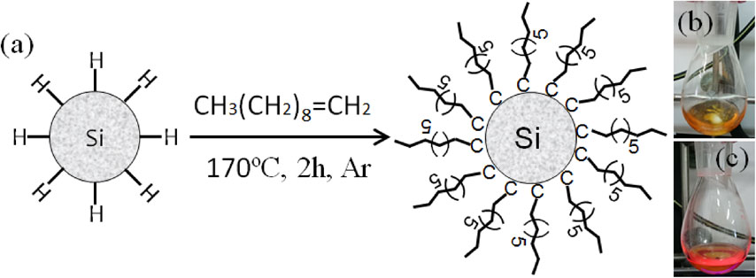
Figure 3 presents the encapsulation process of ncSi-De into the hollow silica particles. Figure 3(a) presents the pore size distribution calculated from the nitrogen adsorption-desorption isotherm measured at 77 K. The specific surface area calculated with the BET theory was 296.7 m2/g. Hollow silica particles are believed to have pores about 5 nm in diameter, which is adequate for ncSi-De NCs outside to move into a silica particle. The existence of a pore around 50 nm in diameter has also been reported. To verify the existence of this large pore, hollow powder particles were examined with high-resolution transmission electron microscopy (HR-TEM). A typical HR-TEM image is inserted in Fig. 3(a). The HR-TEM image showed that the hollow particles were shaped like a cube with an average particle size of 50 nm when the shell wall was about 10-nm thick. Interestingly, no pore comparable to those of 50 nm in diameter was found. From this observation, we considered that the 50 nm pores observed in the pore size distribution curve are gaps formed between particles within the silica particle aggregate.
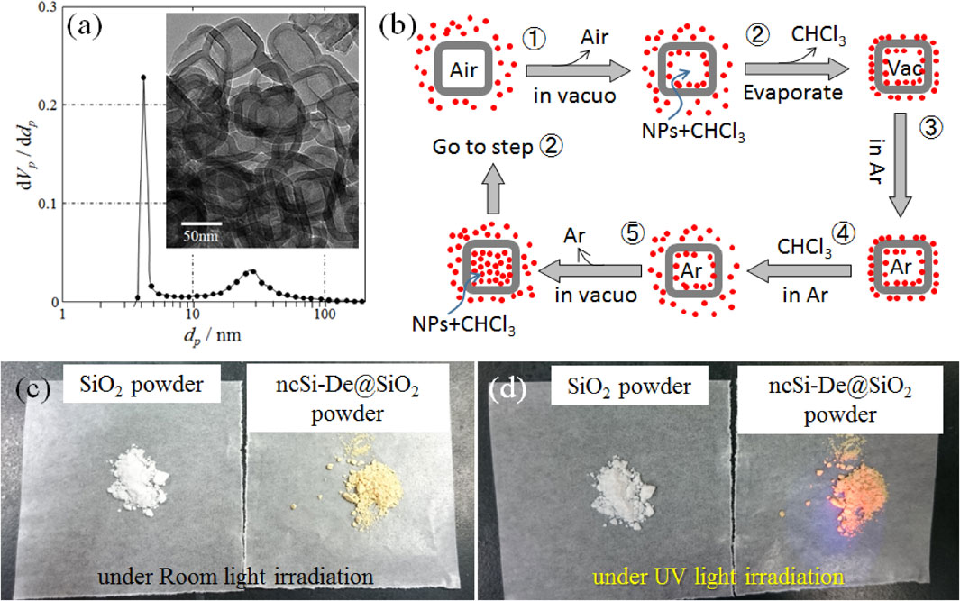
Figure 3(b) shows the encapsulation process of ncSi-De. A ncSi-De-dispersed chloroform solution was transferred to an eggplant-shaped flask connected to a vacuum line. Hollow silica particles were immersed in the transferred solution of the eggplant-shaped flask. Creating a very low vacuum in the flask generated bubbles in the solution, which are attributed to the release of air from the pores of the hollow silica particles (Step 1). To reduce the pressure difference generated under a very low vacuum across the shell of a hollow particle, it was expected that the chloroform solution would enter the hollow particles through the pores. The flask was left undisturbed until no bubbles were observed. The observation of no bubbles was used as an indicator that the hollow space was impregnated with the chloroform solution. Chloroform was then removed by an evaporator (Step 2). Residual ncSi-De that was not encapsulated was physisorbed to the surface of hollow particles. The reaction mixture in the flask was left under an Ar atmosphere (Step 3). Filling the flask with the chloroform solution again (Step 4) redispersed the physisorbed ncSi-De into the solution. Creating a very low vacuum again (Step 5) impregnated the hollow particles with the chloroform solution. By repeating this process, the number of encapsulated ncSi-De increased. Finally, physisorbed ncSi-De was removed by careful washing. Figure 3(c) shows photographs of hollow silica powder taken before and after the encapsulation process. The color of the hollow silica powder was white (left) before encapsulation but became slightly colored (right) after encapsulation of ncSi-De. By repeating the encapsulation process, the concentration of encapsulated ncSi-De was increased and the powder color became darker. Figure 3(d) shows the fluorescent images of the powder before and after the encapsulation process. Under 365 nm ultraviolet light irradiation, the unencapsulated hollow silica powder did not fluoresce but fluoresced red after the encapsulation process.
The hollow silica particles used in this research have a low thermal conductivity (up to 0.02 W/mk). Hence, they have potential for a broad range of applications. For instance, they are used to make window materials that take advantage of their light absorbance property due to the electron configuration of the NCs. In this research, we examined the effect of encapsulation of ncSi into the hollow silica particles to suppress the oxidation of ncSi as well as to increase the heat resistance. To determine the effect of hollow silica particles, in-situ PL measurements were conducted using ncSi:H and ncSi:De as references. More specifically, heater substrates were used as sample holders and the samples were directly drop-casted on the surface of the substrates. The change in the PL spectra was monitored in-situ while the sample temperature was varied.
Figure 4 shows the temperature dependence of the PL spectra. As the temperature increased, the PL intensity decreased in all the samples. The Si:H sample exhibited a considerable decrease in the PL intensity, whereas the ncSi-De and ncSi-De@SiO2 samples exhibited moderate decreases. Figure 5(a) shows the temperature dependence of the PL intensity. The values of the PL intensity normalized to the values recorded at 25°C were plotted. The heat resistance of ncSi:H was low. The PL intensity decreased to 65% of the initial intensity at 50°C. It sharply decreased to 20% at 100°C and further decreased to 14% when the temperature reached 120°C. In contrast, the presence of an alkyl monolayer substantially improved the heat resistance. The PL intensity remained above 80% up to 70°C. Even at 100°C, it was 67% of the intensity at 25°C. Encapsulation of ncSi-De into the hollow silica particles slightly improved the heat resistance.
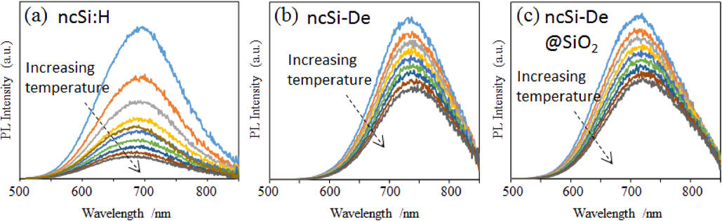

Figure 5(b) plots the converted values of the shift amount of the PL peak energy observed in Fig. 4 in terms of the wavelength. As the temperature increased, the PL peak of ncSi:H shifted towards the shorter wavelength. The shift amount became substantial above 100°C, and exhibited an 18-nm blueshift at 120°C. The shift is believed to be due to the increase in the effective band gap caused by a decrease in the particle size, for which the oxidization of the Si nanocrystal surface associated with the increase in atmospheric temperature is responsible. Conversely, the PL spectra of ncSi-De and ncSi-De@SiO2 exhibited a redshift as the temperature increased. This is attributed to the decrease in the effective band gap caused by the expansion of the crystal lattice associated with the increase in temperature.28) As shown in Fig. 5(b), the shift amount of PL peak energy varied substantially by sample. The shift amount of ncSi-De was less than 5 nm up to 100°C but was more than 10 nm when the temperature exceeded 100°C, exhibiting a substantial redshift. On the other hand, encapsulation into the hollow silica particles substantially suppressed the shift amount associated with the increase in temperature compared with the case of ncSi-De. This difference in the temperature dependence is attributed to the heat resistance effect exerted by Ar and air inside the hollow silica particles.
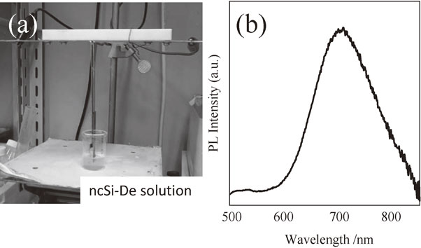
Applying a constant voltage to the EPD device shown in Fig. 6(a) while both substrates were immersed in a 20 mL dispersion gradually reduced the electric current in the circuit. This implies an IR loss due to the formation of a deposition layer over the surface of ITO coated glass. The electric current became constant about one minute after applying the voltage. Then, the ITO substrates were removed and slow-dried overnight. The deposition layers were evaluated using the PL spectra. As shown in Fig. 6(b) we see PL spectrum from the ITO-coated substrate after the EPD treatment. Since the peak energy and spectral width of this PL spectrum agree well with the characteristic properties of ncSi-De@SiO2, it is concluded that the deposition layer is a thin film of ncSi-De/SiO2. The deposition was observed over the anode. According to the discussion of Uchikoshi et al.,29) it is considered to be due to the reversal of the surface charge caused by the adsorption of hydrogen ions (protons) generated in the reaction of magnesium nitrate to the negatively charged surface of ncSi-De@SiO2 particles.
4. Conclusion
This research elucidated the effect of encapsulation of single nano-sized inorganic crystals into hollow silica particles, which suppresses the deterioration of the PL properties emitted from the NCs. This effect is attributed to the high thermal insulation of the atmosphere coexisting with the NCs within the hollow silica particle. This research demonstrated the potential of silica capsule powder with ncSi inside, which allows the production of a thin film by EPD while maintaining the photoluminescence properties of ncSi and hence should contribute towards increasing the versatility of electronic device manufacturing.
Acknowledgments
This study was supported by the WPI-Program, JST A-step (AS282I006e), Sumitomo Foundation.
REFERENCES
- 1) G.H. Carey, A.L. Abdelhady, Z. Ning, S.M. Thon, O.M. Bakr and E.H. Sargent: Chem. Rev. 115 (2015) 12732–12763.
- 2) W. Sun, C. Qian, L. He, K.K. Ghuman, A.P.Y. Wong, J. Jia, A.A. Jelle, P.G. O’Brien, L.M. Reyes, T.E. Wood, A.S. Helmy, C.A. Mims, C.V. Singh and G.A. Ozin: Nat. Commun. 7 (2016) 12553.
- 3) M. Nasilowski, B. Mahler, E. Lhuillier, S. Ithurria and B. Dubertret: Chem. Rev. 116 (2016) 10934–10982.
- 4) X. Dai, Z. Zhang, Y. Jin, Y. Niu, H. Cao, X. Liang, L. Chen, J. Wang and X. Peng: Nature 515 (2014) 96–99.
- 5) G. Xu, S. Zeng, B. Zhang, M.T. Swihart, K. Yong and P.N. Prasad: Chem. Rev. 116 (2016) 12234–12327.
- 6) S. Chandra, G. Beaune, N. Shirahata and F.M. Winnik: J. Mater. Chem. B 5 (2017) 1363–1370.
- 7) G. Hu, T. Albrow-Owen, X. Jin, A. Ali, Y. Hu, R.C.T. Howe, K. Shehzad, Z. Yang, X. Zhu, R.I. Woodward, T. Wu, H. Jussila, J. Wu, P. Peng, P. Tan, Z. Sun, E.J.R. Kelleher, M. Zhang, Y. Xu and T. Hasan: Nat. Commun. 8 (2017) 278.
- 8) K. Black, J. Singh, D. Mehta, S. Sung, C.J. Sutcliffe and P.R. Chalker: Sci. Rep. 6 (2016) 20814.
- 9) N. Shirahata and A. Hozumi: Chem. Mater. 17 (2005) 20–27.
- 10) J. Wei, N. Schaeffer and M.-P. Pileni: Chem. Mater. 28 (2016) 293–302.
- 11) Y. Yu, C.A. Bosoy, D. Smilgies and B.A. Korgel: J. Phys. Chem. Lett. 4 (2013) 3677–3682.
- 12) T. Uchikoshi, S. Furumi, N. Shirahata, T. Suzuki and Y. Sakka: J. Am. Ceram. Soc. 91 (2008) 1674–1677.
- 13) B. Ghosh and N. Shirahata: Sci. Technol. Adv. Mater. 15 (2014) 014207.
- 14) L. Canham: Nature 408 (2000) 411.
- 15) K.A. Littau, P.J. Szajowski, A.J. Muller, A.R. Kortan and L.E. Brus: J. Phys. Chem. 97 (1993) 1224–1230.
- 16) B. Ghosh, M. Takeguchi, J. Nakamura, Y. Nemoto, T. Hamaoka, S. Chandra and N. Shirahata: Sci. Rep. 6 (2016) 36951.
- 17) M.L. Mastronardi, F. Maier-Flaig, D. Faulkner, E.J. Henderson, C. Kübel, U. Lemmer and G.A. Ozin: Nano Lett. 12 (2012) 337–342.
- 18) M. Dasog, J. Kehrle, B. Rieger and J.G.C. Veinot: Angew. Chem. Int. Ed. 54 (2015) 2–20.
- 19) K. Cheng, R. Anthony, U.R. Kortshagen and R.J. Holmes: Nano Lett. 11 (2011) 1952–1956.
- 20) F. Maier-Flaig, J. Rinck, M. Stephan, T. Bocksrocker, M. Bruns, C. Kübel, A.K. Powell, G.A. Ozin and U. Lemmer: Nano Lett. 13 (2013) 475–480.
- 21) B. Ghosh, Y. Masuda, Y. Wakayama, Y. Imanaka, J. Inoue, K. Hashi, K. Deguchi, H. Yamada, Y. Sakka, S. Ohki, T. Shimizu and N. Shirahata: Adv. Funct. Mater. 24 (2014) 7151–7160.
- 22) B. Ghosh, M. Ogawara, Y. Sakka and N. Shirahata: Chem. Lett. 41 (2012) 1157–1159.
- 23) N. Shirahata: Phys. Chem. Chem. Phys. 13 (2011) 7284–7294.
- 24) N. Shirahata, D. Hirakawa and Y. Sakka: Green Chem. 12 (2010) 2139–2141.
- 25) S. Chandra, B. Ghosh, G. Beaune, U. Nagarajan, T. Yasui, J. Nakamura, T. Tsuruoka, Y. Baba, N. Shirahata and F.M. Winnik: Nanoscale 8 (2016) 9009–9019.
- 26) S. Chandra, Y. Masuda, N. Shirahata and F.M. Winnik: Angew. Chem. Int. Ed. 56 (2017) 6157–6160.
- 27) T.K.N. Nguyen, B. Bouteille, F. Grasset, S. Cordier, P. Lemoine, N. Ohashi and T. Uchikoshi: Meeting Abst. 55th. Symposium on Basic Science of Ceramics (2017) p. 95.
- 28) C.E. Rowland, D.C. Hannah, A. Demortière, J. Yang, R.E. Cook, V.B. Prakapenka, U. Kortshagen and R.D. Schaller: ACS Nano 8 (2014) 9219–9223.
- 29) C. Zhang, T. Uchikoshi, L. Liu, Y. Sakka and N. Hirosaki: Materials 7 (2014) 3623–3633.