Abstract
A novel interconnection mechanism using a solderable polymer composite (SPC) with a low-melting-point alloy (LMPA)/high-melting-point alloy (HMPA) mixed filler was proposed to enhance the properties of the LMPA filler and establish a conduction path containing the HMPA filler. To investigate the feasibility of the proposed interconnection mechanism, three types of SPC with a different mixing ratios of LMPA/HMPA filler (100:0, 50:50, and 0:100) were formulated. The SPC with only an HMPA filler showed weak conduction path formation due to excessive curing of the polymer composite before melting of the HMPA filler. In contrast, the SPC with an LMPA/HMPA mixed filler formed a stable and wide conductive path due to the suitable flow-coalescence-wetting behaviors of the molten LMPA filler containing solid-state HMPA filler, which came into effect before excessive curing of the polymer composite.
1. Introduction
Solderable polymer composites (SPCs), which are mainly composed of a functionalized polymer composite with fluxing capability and a fusible alloy filler, have been introduced to overcome the problems of conventional electrically conductive adhesives (ECAs). This approach combines the advantages of solder materials (such as metallurgical conduction path formation) and merits of conventional ECAs (such as low processing temperatures and simplified interconnection processes). In previous works, we confirmed that SPCs can achieve excellent electrical and mechanical properties and thermomechanical reliability through the formation of a metallurgical conduction path by the molten alloy fillers.1–3) In the formulation of SPCs, the Sn/58Bi eutectic solder alloy with a lower melting temperature (Tm = 412 K) than the curing temperature (Tc) of the polymer composite has normally been used as a low-melting-point alloy (LMPA) fillers to achieve excellent interconnection joints via the proper rheology-coalescence-wetting behaviors of the molten fillers. However, SPCs with Sn/58Bi filler have several problems, including decreased ductility of interconnection joint due to the embrittling nature of Bi4) and decreased reliability due to Bi segregation or coarsening at the bonding interface.5) In addition, the application of SPCs with LMPA fillers for joints exposed to high-temperature environments is limited by the low melting temperature of the Sn/58Bi filler. When applying high-melting-point alloy (HMPA) fillers (e.g., Sn/3Ag/0.5Cu, Sn/3.5Ag, Sn/0.7Cu, etc.) to SPCs, the rheology-coalescence-wetting behaviors of molten fillers is hindered because excessive curing of the polymer composite occurs before the melting of the HMPA filler. If the curing temperature or curing time of the polymer composite is increased to prevent rapid curing before the HMPA filler melts, the package assemblies are subjected to higher reflow temperatures due to the high curing temperature of the polymer composite, and the mechanical properties of the joint also deteriorate due to incomplete curing.
Many studies have been reported on Sn/58Bi eutectic solders with added alloying elements (e.g., Ag,5) Cu,6) In,7) Ni,8) etc.) toward improving the solder properties. However, efforts to not only improve the properties of Sn/58Bi solders but also to investigate conduction path formation in solders containing HMPA filler in the SPC system have not been reported.
In this paper, we propose a novel interconnection mechanism using an SPC with an LMPA/HMPA mixed filler to enhance the properties of the LMPA (i.e., Sn/58Bi) filler and establish a conduction path containing the HMPA filler. As the HMPA mixes into the LMPA, the interconnection properties (e.g., ductility, fracture toughness) of the SPC joints can be enhanced because of a change in the microstructure arising from reduced total Bi content within the conduction path.9) Figure 1 shows the newly proposed interconnection mechanism using an SPC with an LMPA/HMPA mixed filler. During the reflow process, the viscosity of the polymer composite gradually decreases, and the oxide layers on the surface of the fillers and electrodes on the printed circuit board (PCB) are eliminated by a chemical reaction between the oxide layer and carboxylic groups (–COOH) of the reductant. As the temperature reaches the melting point of the LMPA filler, it melts and coalesces with nearby filler due to internal flow within the polymer composite. At this point, non-melted HMPA filler is entrapped within the largely grown LMPA filler by contact and integration. Metallurgical conduction paths are then established by the selective wetting behavior of the molten LMPA filler for metallization. Through this wetting behavior of the molten LMPA fillers, which includes the solid-state HMPA filler, the LMPA and HMPA fillers within the SPC concentrate on the metallization region. When the temperature reaches the curing onset temperature of the polymer composite, the polymer begins to cure. As the temperature reaches the melting point of the HMPA filler, the HMPA filler melts, and conduction paths are completely established by the formation of a solid solution between the molten LMPA and HMPA fillers. Finally, the interconnection process is finished by complete curing of the polymer composite.

To investigate the feasibility of the proposed interconnection mechanism using an SPC with an LMPA/HMPA mixed filler, wetting test and chip resistor interconnection test were conducted using the formulated SPCs, and the morphologies of the conduction paths with different filler compositions were observed and compared.
2. Experimental
As listed in Table 1, the formulated SPCs mainly consisted of a polymer composite and solder fillers. The polymer composite was formulated with base resin (diglycidyl ether of bisphenol A; Kukdo Chemical) and minor organic additives (curing agent: 4,4′-diaminodiphenylmethane; TCI Korea, and catalyst: boron trifluoro-mono-ethylamine; Wako Pure Chemical). To remove the surface oxide layers of the fillers and electrodes, carboxylic acid (Aldrich Chemical) was used as a reductant. The curing temperature of formulated polymer composite is approximately 427 K.1) Two types of solder powder (Sn/58Bi (Tm = 412 K) as an LMPA filler, Sn/3Ag/0.5Cu (Tm = 492 K) as an HMPA filler), each with a particle diameter of 45 µm, were obtained from Heraeus. To compare the conduction path formation properties of the formulated SPCs depending on filler composition, three types of SPCs with different mixing ratios between LMPA and HMPA fillers (SPC 1: 100:0, SPC 2: 50:50, and SPC 3: 0:100) were formulated.

Table 1 Components of SPC formulations.
To investigate the flow-coalescence-wetting behaviors of the filler within the polymer composite depending on the filler composition, a wetting test was conducted for a line-type Cu pattern (5.0 mm × 0.1 mm × 0.018 mm in size, 300 µm in pattern pitch)-formed wetting test coupon. For the wetting test, each formulated SPC with a filler volume fraction of 30% was entirely deposited on contact region (including electrode and PCB regions) of the cleaned test coupon as an anisotropic conductive adhesive (ACA). Then, the deposited SPC layer was covered by a transparent glass board to observe the flow-coalescence-wetting behavior of the filler. To determine the standoff height, copper wires with a diameter of 100 µm were placed between the test coupon and upper glass board. The test coupon was then reflowed.
For the interconnection test, a 104-chip resistor with Sn-plated I/O terminals (Samsung Electro-Mechanics; 6.30 mm × 3.20 mm × 0.60 mm in size) and a Cu-plated PCB (32 mm × 32 mm × 1.0 mm in size) were used. Each formulated SPC with a filler volume fraction of 40% was selectively applied to the electrode of the cleaned PCB by the squeegee method as an isotropic conductive adhesive (ICA), to which the chip resistor was then aligned and mounted. The test vehicle was then reflowed using a chip bonder (LAMBDA; Finetech). After completion of the interconnection test, the morphology of the conduction path was observed using an optical microscope (VHX-1000; Keyence).
3. Results and Discussion
In consideration of the curing temperature of polymer composite (Tc = 427 K) and melting temperature of solder materials (Tm, Sn/58Bi = 427 K, Tm, Sn/3Ag/0.5Cu = 492 K), two types of reflow profiles for the wetting and interconnection tests were determined as shown in Fig. 2. In reflow profile 1 used for SPC 1 with LMPA filler only, the test vehicle was heated from room temperature to a reflow peak temperature (Tp) of 433 K at a heating rate of 38 K/min to melt the LMPA filler, and then the temperature was held at 433 K for 3 min to completely cure the polymer composite. In reflow profile 2 used for SPC 2 with an LMPA/HMPA mixed filler and SPC 3 with HMPA filler only, the assemblies were heated from room temperature to 513 K (Tp) at a heating rate of 60 K/min to melt the HMPA filler and then maintained at 513 K for 3 min. Additionally, to confirm the conduction path formation mechanism by the molten LMPA filler before melting of the HMPA filler, SPC 2 was also reflowed under profile 1 conditions.

Figure 3 shows the wetting morphology of the solder fillers within each formulated SPC with different filler compositions for the line-type Cu pattern-formed wetting test coupon. As shown in Fig. 3(a), the LMPAs, which were uniformly dispersed in SPC 1 at initial conditions, were concentrated on the line-type Cu pattern during the reflow process under profile 1 owing to the proper internal flow-coalescence-wetting behaviors of molten filler within the polymer composite with a low viscosity. In contrast, as illustrated by Fig. 3(d) which shows the wetting morphology of the HMPA filler in SPC 3 after the wetting test under reflow profile 2, although the reflow peak temperature was higher than the melting temperature of the HMPA filler, wetting of the HMPA filler for the line-type Cu pattern did not occur, and most of the filler remained in its original condition. This phenomenon may be attributed to excessive curing of the polymer composite. The melting peak temperature of the HMPA filler (492 K) was higher than the curing peak temperature of the polymer composite (427 K). This means that the polymer composite wrapped around the filler had been excessively cured when the reflow temperature reached the melting temperature of the HMPA filler. As a result, the internal flow-coalescence-wetting behaviors of the molten filler were hindered, and thus the molten filler remained in its original condition.
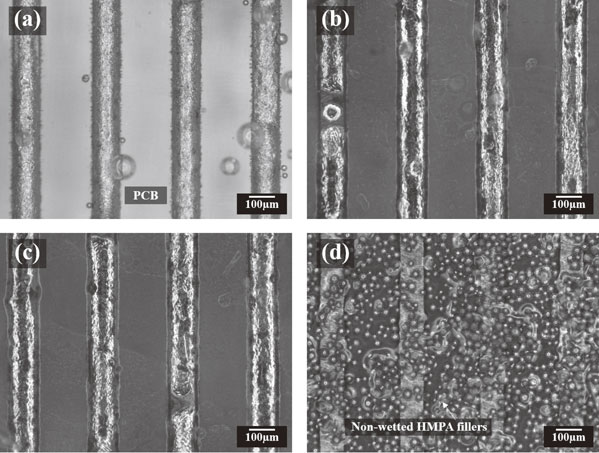
Figure 3(b) and (c) show the wetting morphologies of SPC 2 (with LMPA/HMPA mixed filler) under the reflow conditions of profiles 1 and 2, respectively. The LMPA/HMPA mixed fillers were completely concentrated on the line pattern during the reflow process, regardless of reflow peak temperature conditions. These results indicate that the solid-state HMPA filler can be supplied to the electrode regions via the proper flow-coalescence-wetting behaviors of the molten LMPA filler before excessive curing of the polymer composite occurs.
Figure 4 shows the morphologies of the conduction paths between the chip resistor and PCB for the formulated SPCs with different filler compositions. The interconnected joint has two distinct regions: the conductive path region composed of molten filler, and the cured polymer wrapped around the outside of the conduction path. As shown in Fig. 4(a), a chip resistor assembly using SPC 1 (with LMPA filler only) formed a stable metallurgical conduction path between the metallization of the chip resistor and substrate due to the excellent coalescence and wetting behaviors of the molten LMPA filler within the polymer composite under low-viscosity conditions. On the other hand, as shown in Fig. 4(d), the HMPA filler in SPC 3 under reflow profile 2 conditions was neither coalesced nor wetted. Although a partial interconnection between the upper and lower metallizations was produced by physical contact, the coalescence between the fillers and wetting on the metallizations were not remarkable, and most filler remained in its original condition because excessive curing of the polymer composite materials occurred before melting of the HMPA filler.

Figure 4(b) shows the conduction path morphology formed SPC 2 (LMPA/HMPA mixed filler) reflowed under profile 1 conditions (i.e., reflow peak temperature of 433 K) to confirm the conduction path formation mechanism of the molten LMPA filler before melting of the HMPA filler. Although there are lots of void in the established conduction path (such a phenomenon may be attributed to the surface tension of molten LMPA filler for the non-melted spherical HMPA filler), the non-melted spherical HMPA filler particles were entrapped and connected by the coalesced molten LMPA filler, and interconnected networks between the upper and lower metallizations were formed by the internal flow-coalescence-wetting behaviors of the molten LMPA filler before excessive curing of the polymer composite occurred. Meanwhile, as shown in Fig. 4(c), for SPC 2 reflowed under profile 2 conditions with a reflow peak temperature of 513 K, where the reflow peak temperature was above the melting temperature of the HMPA filler, the entrapped HMPA filler within the coalesced and wetted LMPA filler was melted, and thus a wide and stable conduction path without any void was formed.
4. Conclusion
In this study, novel SPCs with an LMPA/HMPA mixed filler were fabricated, and their interconnection mechanism was investigated. The wetting and interconnection test results showed that SPC 1, with LMPA filler only, formed a stable metallurgical conduction path due to the proper internal flow-coalescence-wetting behaviors of the molten filler within the polymer composite under low-viscosity conditions. In contrast, SPC 3, with HMPA filler only, formed a weak conduction path due to excessive curing of the polymer composite before melting of the HMPA filler. However, when the LMPA/HMPA mixed filler was introduced into the SPC, a stable and wide conductive path was formed due to the proper flow-coalescence-wetting behaviors of the molten LMPA filler containing the solid-state HMPA filler before excessive polymer composite curing occurred and formation of a solid solution between the LMPA and HMPA fillers through the melting of the HMPA filler.
From the results of the present study, we confirmed the feasibility of the newly proposed interconnection mechanism using an SPC with an LMPA/HMPA mixed filler. Base on this interconnection mechanism, we expect that the formed conduction path in the LMPA/HMPA mixed filler may be able to improve the properties of LMPA joints, such as weak interconnection and reliability properties due to the brittle nature of Bi within the LMPA solder composite and limited applicability to joints exposed to high-temperature environments due to low melting temperature by the formation of a solid solution between the LMPA and HMPA fillers. A further investigation into the interconnection properties and reliability of SPC joints with LMPA/HMPA mixed fillers will be performed and reported in the near future.
Acknowledgements
This research was supported by Basic Science Research Program through the National Research Foundation of Korea (NRF) funded by the Ministry of Science, ICT and future Planning (Grant No. 2017R1C1B5076997) and the Chung-Ang University Research Scholarship Grants in 2018.
REFERENCES
- 1) B.S. Yim, J.M. Kim, S.H. Jeon, S.H. Lee, J. Kim, J.G. Han and M. Cho: Mater. Trans. 50 (2009) 2649–2655.
- 2) B.S. Yim, Y. Kwon, S.H. Oh, J. Kim, Y.E. Shi, S.H. Lee and J.M. Kim: Microelectron. Reliab. 52 (2012) 1165–1173.
- 3) B.S. Yim, J.I. Lee, Y. Heo, J. Kim, S.H. Lee, Y.E. Shin and J.M. Kim: Mater. Trans. 53 (2012) 2104–2110.
- 4) F. Hua, Z. Mei and J. Glazer: Proc. 48th IEEE Electronic Components and Technology Conference 47, (1998) pp. 277–283.
- 5) M. McCormack, H.S. Chen, G.W. Kammlott and S. Jin: J. Electron. Mater. 26 (1997) 954–958.
- 6) H. Takao, A. Yamada and H. Hasegawa: R&D Review of Toyota CRDL 39 (2004) 49–56.
- 7) X. Chen, F. Xue, J. Zhou and Y. Yao: J. Alloy. Compd. 633 (2015) 377–383.
- 8) K. Kanlayasiri and T. Ariga: Mater. Des. 86 (2015) 371–378.
- 9) F. Wang, Y. Huang, Z. Zhang and C. Yan: Materials 10 (2017) 920.
