Abstract
Vertical-type high-speed twin-roll casting is a candidate method to realize up-grade recycling of aluminum, in which cast alloy is used to produce wrought alloy products due to its rapid solidification. Using A356 aluminum alloy (Al–Si–Mg) strips to produce wrought alloy sheets requires isotropy and high ductility for good formability. However, the elongation of the cold-rolled and annealed A356 strips after vertical-type high-speed twin-roll casting is different in the rolling direction (RD) and the transverse direction (TD) of the strips. In this study, strips of pure Al, Al–2% Si, and Al–7% Si alloys were fabricated by vertical-type high-speed twin-roll casting to investigate the effect of eutectic Si particles on the elongation anisotropy of the cold-rolled and annealed strips. The effect of increasing the rolling reduction rate of the strips on the reduction of the elongation anisotropy was examined. Elongation anisotropy was not observed in pure Al, whereas it was observed in Al–2% Si and Al–7% Si, and it was more pronounced in Al–7% Si. Although the eutectic Si particles were randomly distributed in the RD cross section, they were oriented in the RD in the TD cross section. When the strip was loaded in the TD, the voids that formed around the eutectic Si particles were often connected perpendicular to the load direction during the tensile test, and the elongation decreased. To reduce the elongation anisotropy, it is necessary to create a uniform distribution of eutectic Si particles in both the RD and TD cross sections. Tandem vertical-type high-speed twin-roll casting was used to fabricate a thick strip while maintaining the rapid cooling rate. In the clad strips, elongation increased in the TD, and the elongation anisotropy was reduced. Anisotropy was not observed in the five-layer clad strip because the eutectic Si particles were uniformly distributed by the increase in the rolling reduction rate due to the increase of the initial strip thickness.
1. Introduction
Aluminum is one of the most suitable materials for recycling because it can be recycled with a few percent of the electricity of virgin ingot production for use in wrought alloy products. Recycled alloy made from aluminum product scrap has lower mechanical properties than the virgin alloy. Therefore, recycled aluminum alloys are generally downgraded to cast products. However, it is predicted that there will be an oversupply of aluminum product scrap in the near future. Therefore, recycling methods are urgently needed that allow cast alloy scrap to be upgraded to wrought alloys and allow horizontal recycling of wrought alloy scrap to wrought alloys.
The vertical-type high-speed twin-roll casting method used in this research is a unique method for fabricating aluminum alloy strips directly from the molten metal.1,2) A strip several millimeters thick can be produced directly from the melt at a high speed of 30 to 150 m/min, and the subsequent hot-rolling process can be omitted. A schematic of the vertical-type high-speed twin-roll caster3) used in this study is shown in Fig. 1. The caster consists of a pair of rotating water-cooled pure copper rolls, a spring for applying load to the strips, nozzles, and side-dams for making a melt pool. The diameter and width of the pure copper rolls are 300 and 100 mm, respectively. One roll is firmly fixed to the pedestal, whereas the other roll is attached to the pedestal with springs, which apply the load to the solidifying strip. The spring load is used to achieve firm contact between the roll surfaces and the solidification shells to allow excellent heat extraction and high cooling rates. The cooling rate during solidification is about 1000°C/s, which is sufficient to refine the microstructure, to make the impurities elements harmless, and promote the supersaturation of solute atoms in the matrix.4–7) Because of these advantages, vertical-type high-speed twin-roll casting is a candidate method to allow recycled aluminum to be upgraded, so that cast alloy scrap can be used to produce wrought alloy products.

A356 aluminum alloy (Al–Si–Mg) is a representative cast alloy. To produce wrought alloy sheets, the A356 strips fabricated by vertical-type high-speed twin-roll casting must be isotropic and highly ductile to achieve good formability. However, the elongation of the cold-rolled and annealed A356 strips after vertical-type high-speed twin-roll casting is different in the rolling direction (RD) and transverse direction (TD) of the strips.8) The main component in A356 alloy is 7 mass% (hereafter abbreviated as “%”) Si. Therefore, we focused on the Al–Si binary alloy. In this study, strips of pure Al, Al–2% Si, and Al–7% Si were fabricated by vertical-type high-speed twin-roll casting to investigate the effect of eutectic Si particles on the elongation anisotropy of the cold-rolled and annealed strips. The relation between the distribution of the eutectic Si particles and the elongation anisotropy of the cold-rolled and annealed Al–7% Si alloy strips was also investigated. The effect of increasing the rolling reduction rate on the reduction of the elongation anisotropy was examined.
2. Experimental Procedures
2.1 Fabrication of strips
Pure Al (3N), Al–2% Si, and Al–7% Si alloys were used; their chemical compositions are listed in Table 1. The strips were fabricated by vertical-type high-speed twin-roll casting; the casting parameters are listed in Table 2. A tandem vertical-type high-speed twin-roll caster, in which three vertical-type high-speed twin-roll casters are arranged vertically, was also used in this study.9–11) A schematic of the tandem caster used in this study is shown in Fig. 2. The diameter and the width of the pure copper rolls are 200 and 40 mm (first roll), 45 mm (second roll), and 50 mm (third roll). The clad sheet is fabricated in one step by casting the core strip in the first roll and subsequent casting of the alloy used as the skin strip in the second and third rolls. A three-layer or five-layer clad is formed by using two twin rolls or three twin rolls, respectively. The Al–7% Si alloy was used for both the core and the skin strip to fabricate the three-layer and the five-layer clad strips. The casting parameters are listed in Table 3. The ingot was melted in a graphite crucible in an electric furnace under an argon gas atmosphere. The melt was degasified by blowing argon gas into the melt at 750°C for 20 min. The crucible containing the molten metal was removed from the furnace and the molten metal was poured into the nozzle at a temperature 10°C–20°C higher than the liquidus temperature. The strips from the single caster were 100 mm wide, about 3 m long, and 2–3 mm thick, and those from the tandem caster were 45–50 mm wide, about 2 m long, and 5–7 mm thick, depending on the casting parameters. The specimens were cut from the central part in the casting direction of the strips with a constant thickness, and were used for subsequent microstructural observation and cold-rolling. The RD was the same as the casting direction. The rate of rolling reduction to 1 mm thickness was 50%–85%, depending on the initial strip thickness.

Table 1 Chemical composition of pure Al and Al–Si alloys used in this study, mass%.

Table 2 Casting parameters for vertical-type high-speed twin-roll casting.
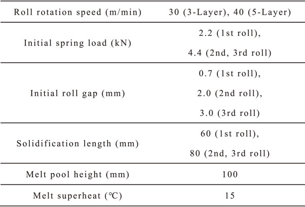
Table 3 Casting parameters for tandem vertical-type high-speed twin-roll casting.
Small tensile test specimens were taken from the rolled strips (Fig. 3). The specimens were annealed (520°C, 1 h) and water cooled. The tensile test was carried out using an Instron type testing machine at a crosshead speed of 1 mm/min at room temperature. The loading directions were the RD and TD of the rolled strip.
2.3 Microstructural observation
The cross section of the Al–7% Si alloy strip (as-cast, after cold-rolling and annealing) was ground with waterproof abrasive paper sheets up to #2000 grit, and then polished with diamond pastes (6, 3, and 1 µm) and a colloidal silica suspension. The polished surfaces were etched with 2% NaOH aqueous solution. The microstructures were observed with an optical microscope.
2.4 Quantification of eutectic Si particle distribution
When there are several points on a plane, the Voronoi diagram12) is a plane divided according to which point is closest. The diagram is used in various fields, such as nearest neighbor searches. We created a Voronoi diagram to evaluate quantitatively the distribution of the eutectic Si particles in the cold-rolled and annealed Al–7% Si alloy strip by image analysis. The microstructure of the cold-rolled and annealed Al–7% Si alloy strip was binarized so that the α-Al phase was white and the eutectic Si particles were black (Fig. 4(a)). The binary image was divided by the perpendicular bisector between the closest eutectic Si particles (Fig. 4(b)) to create a Voronoi diagram (Fig. 4(c)) by using Image J software. The cell area in the Voronoi diagram was measured, and the coefficient of variation (CV) was calculated from the standard deviation (σ) and the average value (μ) as
| \begin{equation}
\mathit{CV} = \sigma/\mu
\end{equation}
| (1) |
A smaller
CV value indicated a more uniform eutectic Si particle distribution.
3. Results and Discussion
3.1 Mechanical properties of cold-rolled and annealed strips
The tensile properties of the cold-rolled and annealed strips are shown in Fig. 5. The 0.2% proof stress and the ultimate tensile strength increased with the Si content. There was no significant difference in the values of RD and TD, that is, there was no anisotropy. However, the elongation decreased with the Si content. No anisotropy was observed in pure Al, whereas anisotropy was observed in Al–2% Si and Al–7% Si, and it was greater in Al–7% Si. This result suggests that the anisotropy was caused by eutectic Si particles.

Cross-sectional microstructures of the Al–7% Si alloy strips are shown in Fig. 6. In this figure, CD and ND mean the casting direction and normal direction, respectively. The bright contrast is the primary α-Al phase and the dark contrast is the eutectic Si particles. There was no major difference in the α-Al phase and eutectic Si particles in the RD and TD cross sections of the as-cast specimens (Figs. 6(a), (b)). In contrast, the distribution of the eutectic Si particles was different in the RD and TD cross sections of the cold-rolled (50% reduction) and annealed specimen. Although the eutectic Si particles were randomly distributed in the RD cross section (Fig. 6(c)), they were oriented in the RD in the TD cross section (Fig. 6(d)). The T6-treated A356 alloy fractures via the generation of micro cracks (micro voids) at the interface between the matrix and the eutectic Si particles or inside the particles, and the cracks grow and eventually merge.13) In this study, the loading direction in the tensile test was perpendicular to the paper surface in Fig. 6. In the TD cross section where the eutectic Si particles were oriented in the RD (Fig. 6(d)), the voids that formed around the eutectic Si particles were likely to be connected perpendicular to the load direction during the tensile test, and thus the elongation decreased. To reduce the elongation anisotropy, it is necessary to achieve the uniform distribution of eutectic Si particles in both the RD and TD cross sections.

The effect of the rolling reduction rate on the distribution of the eutectic Si particles was investigated. When the roll rotation speed is reduced in vertical-type high-speed twin-roll casting, the time for solidified shells to grow from both roll surfaces increases and the strip thickness increases. In this study, the Al–7% Si alloy strips (as-cast) with thicknesses of about 2.0 and 2.5 mm were fabricated at roll rotation speeds of 60 and 30 m/min, respectively. Rolled strips 1 mm thick were obtained from the as-cast strips by cold-rolling at reduction rates of about 50% and 60%. Figure 7 shows the elongation of the cold-rolled and annealed Al–7% Si alloy strips at each rolling reduction rate. As the rolling reduction rate increased from 50% to 60%, the elongation in the TD increased slightly, but elongation anisotropy was still observed. The cross-sectional microstructures in the mid-thickness region of each strip are shown in Fig. 8. Although the eutectic Si particles were uniformly distributed in the RD cross section (Figs. 8(a), (c)), they were still oriented in the RD direction in the TD cross section even for the rolling reduction rate of 60% (Figs. 8(b), (d)). This is reason that the elongation anisotropy was not suppressed.


Figure 9 shows the cross-sectional microstructures near the surface of the cold-rolled and annealed Al–7% Si alloy strip at a rolling reduction rate of 60%. In the TD cross section, the eutectic Si particles were uniformly distributed, as in the RD cross section. Therefore, the distribution of the eutectic Si particles was different between the near-surface and the mid-thickness regions of the strip. Figure 10(a) shows cross-sectional images of the as-cast Al–7% Si alloy strips. The eutectic Si particles agglomerated in the mid-thickness region of the strip, which was the final region to solidify. This agglomeration of the eutectic Si particles is referred to as “macrosegregation” hereafter. Macrosegregation was observed even after subsequent cold-rolling and annealing (Fig. 10(b)). The eutectic Si particles were difficult to distribute uniformly after cold-rolling due to the macrosegregation. Achieving a uniform distribution required the reduction of macrosegregation and a further increase in the rolling reduction rate.

Casting thick strips is necessary to increase the rolling reduction rate further. However, the advantages of vertical-type high-speed twin-roll casting, such as microstructural refinement, are lost for thicker strips because the cooling rate decreases in the mid-thickness region. Therefore, tandem vertical-type high-speed twin-roll casting was used to fabricate a thick strip while maintaining the rapid cooling rate. Moreover, because the core and skin both have the final region to solidify, the macrosegregation area of the eutectic Si particles was expected to disperse in several regions of the strip thickness.
Figure 11 shows cross-sectional images of the Al–7% Si alloy clad strips (as-cast). The strip thicknesses were about 5 and 7 mm for the three-layer and five-layer clad strips, respectively. Compared with the single-layer strip, the initial strip thickness was increased considerably. Increasing the layer number of the clad strips dispersed the macrosegregation area of the eutectic Si particles not only in the mid-thickness region of the strips, but also over the whole strip thickness. Increasing the initial strip thickness and the dispersion of the macrosegregation area were expected to decrease the effect of the segregation after cold-rolling with a high rolling reduction rate. The rolling reduction rate could be increased substantially compared with that for the single-layer strips. The rolling reduction rates of the cold-rolled strips (1 mm thick) were about 80% (three-layer clad) and 85% (five-layer clad). Figure 12 shows cross-sectional images of the cold-rolled and annealed Al–7% Si alloy clad strips. The macrosegregation of the eutectic Si particles was reduced compared with the single-layer strips (Fig. 10(b)). Cross-sectional microstructures of the cold-rolled and annealed Al–7% Si alloy clad strips at each rolling reduction rate are shown in Fig. 13. The eutectic Si particles were distributed uniformly in the RD and TD cross sections.

The elongation of the cold-rolled and annealed Al–7% Si alloy clad strips is compared with that of the single-layer strips in Fig. 14. In the clad strips, elongation increased in the TD, and the elongation anisotropy was reduced. No anisotropy was observed in the five-layer clad strip. This is because the eutectic Si particles were uniformly distributed by the increase of the rolling reduction rate due to the increase of the initial strip thickness and the dispersion of the macrosegregation area in the as-cast strips.
3.4 Quantification of eutectic Si particle distribution
The elongation anisotropy of the cold-rolled and annealed Al–7% Si alloy strip fabricated by vertical-type high-speed twin-roll casting was related to the distribution of the eutectic Si particles. The distribution of eutectic Si particles was quantified by image analysis using a Voronoi diagram. Figure 15 shows CV of the eutectic Si particles in the cold-rolled and annealed Al–7% Si alloy strips at each rolling reduction rate. CV for the TD cross section was much larger than that of the RD cross section in the vertical-type high-speed twin-roll cast strip (single-layer), in which the elongation anisotropy was large. This result indicates that the eutectic Si particles were uniformly distributed in the RD cross section, but not in the TD cross section (Fig. 8). In contrast, in the clad strips with the reduced elongation anisotropy, CV in both the RD and TD cross section decreased. This indicates that the eutectic Si particles in the clad strips were more uniformly distributed than those in the single-layer strips.

4. Conclusion
-
(1)
The 0.2% proof stress and ultimate tensile strength of the cold-rolled and annealed strips fabricated by vertical-type high-speed twin-roll casting showed no differences in RD and TD. The elongation was also the same in pure Al. However, in Al–2% Si and Al–7% Si, the elongation was different in the RD and TD, and the difference was greater in Al–7% Si.
-
(2)
Although the eutectic Si particles were randomly distributed in the RD cross section of the cold-rolled and annealed Al–7% Si alloy strips, they were oriented along the RD in the TD cross section. When the strip was loaded in the TD, the voids that formed around the eutectic Si particles were likely to be connected perpendicular to the load direction during the tensile test and the elongation decreased.
-
(3)
Tandem vertical-type high-speed twin-roll casting was used to fabricate a thick strip while maintaining the rapid cooling rate. In the clad strips, the elongation anisotropy was reduced by the increase of the elongation in the TD. Anisotropy was not observed in the five-layer clad strip because the eutectic Si particles were uniformly distributed by increasing the rolling reduction rate through increasing the initial strip thickness, which reduced the macrosegregation in the mid-thickness region of the strips.
REFERENCES
- 1) T. Haga, K. Takahashi, M. Ikawa and H. Watari: J. Mater. Proc. 140 (2003) 610–615.
- 2) T. Haga and S. Suzuki: J. Mater. Proc. 143–144 (2003) 895–900.
- 3) D. Kikuchi, Y. Harada and S. Kumai: J. Manu. Proc. 37 (2019) 332–338.
- 4) K. Suzuki, S. Kumai, Y. Saito, A. Sato and T. Haga: Mater. Trans. 45 (2004) 403–406.
- 5) K. Suzuki, S. Kumai, Y. Saito and T. Haga: Mater. Trans. 46 (2005) 2602–2608.
- 6) K. Tokuda, S. Kumai, K. Suzuki, A. Ishihara and T. Haga: J. JILM 57 (2007) 444–449.
- 7) Y. Harada, H. Yamamoto, S. Nagano, M.S. Kim and S. Kumai: J. JFS 87 (2015) 772–781.
- 8) T. Goda and S. Kumai: Mater. Trans. 59 (2018) 1777–1783.
- 9) R. Nakamura, T. Haga, S. Kumai and H. Watari: Adv. Mater. Res. 97–101 (2010) 1053–1056.
- 10) R. Nakamura, T. Yamabayashi, T. Haga, H. Watari and S. Kumai: J. Solid Mech. Mater. Eng. 5 (2011) 1029–1041.
- 11) R. Nakamura, Y. Tanaka, T. Haga, Y. Harada and S. Kumai: J. JFS 86 (2014) 223–228.
- 12) F. Aurenhammer: ACM Comput. Surv. 23 (1991) 345–405.
- 13) Q.G. Wang: Metal. Mater. Trans. 34 (2003) 2887–2899.


