Abstract
Hydrogen embrittlement of SK85 high-strength steel sheets was evaluated through a three-point bending test. The effects of electroless Ni–P plating and Ni electroplating on hydrogen embrittlement were examined with respect to the hydrogen permeability of the plated films. On the morrow of the plating, electroless Ni–P plating indicates a high degree of hydrogen embrittlement, irrespective of the phosphorus content in the film. However, hydrogen embrittlement of Ni electroplating is further suppressed than that of electroless Ni–P plating, which can be attributed to the excellent hydrogen diffusing ability of Ni electroplating. These results demonstrate that the hydrogen permeability of a plated film is an important factor for hydrogen embrittlement. Hydrogen present on the plated film surface was visualized by employing the hydrogen microprint technique, and the corresponding results reveal that the hydrogen permeability of the plated film is dependent on the film crystal structure. Furthermore, the pits in the film can become a route for hydrogen emission.
This Paper was Originally Published in Japanese in J. Japan Inst. Met. Mater. 84 (2020) 80–86. The horizontal axis of Fig. 5 was corrected.
1. Introduction
Hydrogen embrittlement is a phenomenon, in which the strength and fracture characteristics of a metal deteriorate owing to the absorption of H2 by the metal surface, which could lead to cracking and an early fracture. Thus far, numerous mechanisms have been proposed to explain hydrogen embrittlement. According to the internal pressure theory,1) H atoms gather to form molecular H2 and cracks occur, as the internal pressure increases. The lattice embrittlement theory2) suggests that H atoms gather in areas with a non-uniform arrangement of the metal atoms (dislocation), thereby hindering the intermetallic bonding and decreasing the strength. According to the hydrogen-assisted local plastic deformation theory,3) hydrogen facilitates plastic slip at a crack tip. The hydrogen-assisted strain-induced vacancy theory4) suggests that hydrogen promotes the formation and aggregation of atomic vacancies in plastic deformation, and facilitates the progress of ductile fracture. However, this complex process of hydrogen embrittlement is not yet completely understood.
The susceptibility of steel to hydrogen embrittlement generally increases with the strength of the steel. In particular, in high-strength steels (>1500 MPa), cracks are generated by small amounts of H2 (of the order of a few parts per billion (ppb)), which could lead to serious accidents.5) In the transportation equipment industry, a weight reduction of vehicle bodies is essential to address environmental implications, and this is usually achieved by employing high-strength steel. Therefore, as the applications of high-strength steel increase, it is critical to pay more attention to hydrogen embrittlement. Hydrogen is typically absorbed by metallic materials during corrosion, welding, acid cleaning, and plating. In particular, steel materials are zinc-plated to prevent long-term corrosion through sacrificial protection.6) Therefore, it is necessary to consider the hydrogen embrittlement of zinc-coated high-strength steel caused by the hydrogen generated during the pretreatment pickling and zinc electroplating.7) On the other hand, it was reported that Zn–Ni alloy plating and composite plating, in which silica is dispersed in the coating, showed good resistance to hydrogen embrittlement.8) Thus, the susceptibility to hydrogen embrittlement is a function of the type of plating and the presence of silica. It is speculated that the hydrogen permeability of the plating film is an important factor in assessing hydrogen embrittlement.9) Currently, various platings are being studied with a focus on their hydrogen permeabilities.
The electroless Ni–P plating is applied as an anti-corrosion coating for steel and copper alloys because it does not require an external power source for the deposition of the coating, while at the same time providing a chemically stable coating. In addition, a hard coating of approximately 600 HV can be obtained as deposited; therefore, it is widely used for wear-resistant plating.10) According to Takada,11) based on the delta gauge method, the hydrogen embrittlement rate of electroless Ni–P plating is 1.5% or less, and the risk of hydrogen embrittlement is classified as low. On the other hand, the fatigue strength of an aluminum alloy, plated with electroless Ni–P is lower than that of an untreated aluminum alloy; this behavior is attributed to hydrogen embrittlement.12) Thus, the effect of electroless Ni–P plating on hydrogen embrittlement is still not clearly understood.
In this study, for obtaining electroless Ni–P plating with excellent corrosion, as well as wear resistance, the hydrogen embrittlement of plating films with varying phosphorus content was evaluated by a three-point bending test. The hydrogen content in the films was measured, and the relationship between hydrogen embrittlement and hydrogen permeability of the film was investigated.
2. Experimental Procedure
Steel of grade SK85, whose chemical composition is shown in Table 1, was used as the substrate. The heat treatment described in Table 2 was performed on SK85 and an average hardness value of 640 HV was obtained after the heat treatment. The specimens for the three-point bending test were cut into strips (of size 70 × 4 × 0.5 mm3) using a precision cutting machine, while being cooled by water. To remove the oxide scale generated by the heat treatment, the specimen surfaces were polished using a #600 water-resistant abrasive paper, and then ultrasonically cleaned in acetone. The specimens were immersed in a 0.06 mol/L HCl solution for 10 s for a pre-plating treatment, and then washed with water. Subsequently, in accordance with the plating bath compositions and plating conditions shown in Table 3, three types of electroless Ni–P platings with different phosphorus contents were obtained. In addition, an electrolytic Ni plating was also used for comparison purposes. It was ensured that the resultant film thickness was 5 µm in each specimen. The surfaces of the films thus obtained, were observed by scanning electron microscopy (SEM), and their crystal structures were analyzed by X-ray diffraction (XRD).

Table 1 Chemical composition of SK85. (mass%)
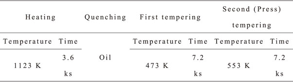
Table 2 Heat treatment condition for SK85.

Table 3 Bath composition and plating conditions.
A micro-autograph (MST-I II type HS/HR) was used for the three-point bending test. The distance between the supports was set at 27 mm; a load was applied at the center; and the load and displacement until the occurrence of a fracture were measured. A low strain rate was important for the evaluation of hydrogen embrittlement, and the displacement rate in this experiment was set at 0.05 mm/min, which enabled the evaluation of the hydrogen embrittlement, based on the results of a previous study.9) The bending stress, σ = M/Z (where M is the bending moment and Z is the section modulus), was determined based on the rupture load, and the bending stress was defined as the rupture stress. The hydrogen embrittlement rate [100 − (rupture stress after the plating/rupture stress of the substrate) × 100 (%)], and the amount of hydrogen were measured over 28 days from immediately after the plating, using a semiconductor H2 sensor gas chromatography-type thermal desorption H2 analyzer (SGHA-P2, Nissha F.I.S. Co. Ltd., Japan; detection sensitivity of 5 ppb) This sensor was used to measure the amount of H2 every 2 min. In addition, the hydrogen microprinting method13) was used to observe the hydrogen released from the base material through the plating film, and onto the surface. The hydrogen was charged to the base material by immersing it in a 3.6 mol/L HCL acid solution and etching the base material. Subsequently, the test piece was mechanically removed from the film on the side opposite to the observation surface, and then set on a jig exposing the surface, from which the film was removed. Considering the hydrogen diffusion coefficient with respect to iron, after the etching, 72 h were allowed for the charged hydrogen to reach the observation surface in an adequate quantity.
3. Results and Discussions
3.1 Surface morphology and crystal structure of the plating films
Figure 1 shows the surface SEM image of each plating film. A smooth coating was obtained for all the electroless Ni–P plating specimens, and undulations peculiar to electroless Ni–P plating were also observed. The effect of the differences in the phosphorus content in the film on the surface morphology was marginal. On the other hand, the electrolytic Ni plating film was different from the electroless Ni–P platings, and fine angular precipitates were observed on the former. Furthermore, upon a detailed observation of the electroless Ni–P films and electrolytic Ni-plated film, fine pits with a size of 100 nm or less, as shown in Fig. 2, were noticed in all the platings.


Figure 3 shows the diffraction pattern of each plating film obtained by XRD. It was observed that the crystal structure of the electroless Ni–P plating was crystalline, when its phosphorus content was less than approximately 8 mass%; however, it became amorphous, as the phosphorous content exceeded the above-mentioned amount. The phosphorus contents of the electroless Ni–P platings used in this study were 1.3 mass% for the low-phosphorus (low-P), 8.5 mass% for the medium-phosphorus (middle-P), and 11.0 mass% for the high-phosphorus (high-P) platings. From the XRD patterns, a broad peak was observed around 43° for the middle-P and high-P films, indicating that these films had an amorphous structure. On the other hand, in the electrolytic Ni plating, diffraction peaks of the (111) plane derived from Ni near 43° and of the (200) plane near 52° were observed. Furthermore, the XRD peak of the low-P film was also similar to that of the electrolytic Ni plating, and both these coatings were crystalline.

One of the characteristics of hydrogen embrittlement is its strain rate dependence; the lower the strain rate, the higher the brittleness.14) Figure 4 shows the relationship between the displacement rate and breaking stress, as obtained by the three-point bending test in the high-P electroless Ni–P plating. As the displacement speed slowed down, the breaking stress decreased, thus promoting the embrittlement. These results indicate that the electroless Ni–P plating had induced hydrogen embrittlement. The breaking stress increased slightly when the displacement rate was lower than 0.01 mm/min. This is probably because, as in the case of Zn–Ni alloy plating,8,9) diffusible hydrogen, which induces hydrogen embrittlement, permeated the plating film, and was released from the substrate during the test. In the above-mentioned evaluation of hydrogen embrittlement measured by the delta gauge method, the hydrogen embrittlement susceptibility of the electroless Ni–P was low; however, in the current experiment, the hydrogen embrittlement was clearly confirmed. The difference between these studies was that the tightening speed in the delta gauge method was 15 mm/min, which was more than two orders of magnitude faster than the displacement speed in the current experiment. Therefore, it was presumed that the embrittlement could not be detected in the former.

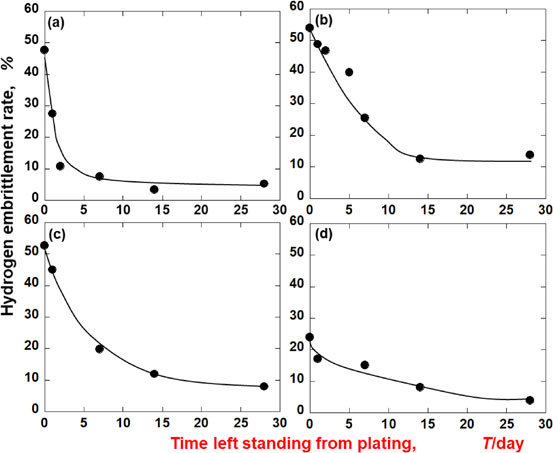
It was found that the electroless Ni–P plating had induced hydrogen embrittlement. Therefore, Fig. 5 shows the relationship between the standing time until the three-point bending test after the plating, and the hydrogen embrittlement degree of each plating film. Immediately after the plating, the degree of hydrogen embrittlement of each electroless Ni–P plating was approximately 50%, thus showing a high degree of hydrogen embrittlement susceptibility. Furthermore, the effect of phosphorus content in the plating film on hydrogen embrittlement was not observed. The 50% hydrogen embrittlement rate of electroless Ni–P plating was similar to that of a Zn plating from a sulfate bath left for two weeks.9) On the other hand, the hydrogen embrittlement rate of the electrolytic Ni plating was only 23.9%, which implied its lower susceptibility to hydrogen embrittlement than any of the electroless Ni–P platings. Thus, it was found that the former’s hydrogen embrittlement resistance immediately after the plating was superior to that of the latter.
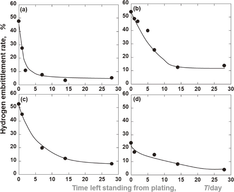
Next, as for the variation of the hydrogen embrittlement rate with time after the plating, it decreased with the passage of days in all the platings. These results indicated that the diffusible hydrogen involved in hydrogen embrittlement, absorbed into the substrate by plating, was released from the substrate over time. Furthermore, the fact that the degree of reduction in the hydrogen embrittlement was dependent on the type of plating suggested that the hydrogen permeabilities of the plating films also differed from one another. In the electroless Ni–P plating, the hydrogen embrittlement rate of the low-P film was remarkably decreased to approximately 10% after two days, and to below 5% after two weeks. Thus, among the three types of electroless Ni–P platings used in this experiment, the low-P type showed the best hydrogen embrittlement resistance. The middle-P and high-P films showed the same tendency as each other; however, after four weeks, the hydrogen embrittlement rate of the high-P film was slightly lower than that of the middle-P type. One month after the plating, the middle-P film had the highest susceptibility to hydrogen embrittlement. On the other hand, the hydrogen embrittlement rate of the electrolytic Ni plating decreased to 3.9% after four weeks, and it was found to be as effective against hydrogen embrittlement as the low-P film.
3.4 Hydrogen measurement
Figure 6 shows the results for hydrogen-release as measured by a gas chromatography-type thermal desorption hydrogen analyzer for the SK85 substrate before the plating, the specimens for pretreatment (pickling), and the specimens immediately after various platings. In the case of the substrate and the specimens for pretreatment before the plating (pickling), the hydrogen-release was very marginal up to a temperature of 400°C, and subsequently, it became significant above 400°C. In addition, because the pretreated-only specimen, as measured by the three-point bending test showed the same value of fracture stress as that of the untreated one, the hydrogen released at 400°C or higher did not contribute to the hydrogen embrittlement.

Next, regarding the plated specimens, an emission peak was observed at approximately 60°C for all the specimens. On comparing these peaks, it was observed that the amount of hydrogen released by the electrolytic Ni plating was the lowest, followed by the low-P electroless Ni–P plating. The amount of hydrogen released for the middle-P and high-P films increased significantly compared to that of the electrolytic Ni plating, as well as the low-P film. Comparing the relationship between the hydrogen embrittlement rate immediately after the plating and the hydrogen release amount in Fig. 5, the hydrogen embrittlement rate of electrolytic Ni plating, which released the least amount of hydrogen, is lower than that of other platings, and the hydrogen embrittlement rate and hydrogen release are correlated. However, the degree of hydrogen embrittlement of various electroless Ni–P platings was approximately 50% regardless of the phosphorus content. Moreover, the amount of hydrogen released from the low-P film was significantly lower than that of the other two types of electroless Ni–P platings. Regarding the hydrogen charged on the test piece at the initial stage of the plating, these results showed that both the hydrogen involved in hydrogen embrittlement and the hydrogen not involved were mixed.
Figure 7 shows the relationship between the total amount of released hydrogen, as obtained from the measurement profiles from immediately after the plating to four weeks, and the standing time after the plating. The amount of hydrogen released over this time varied depending on the plating type. The amount of hydrogen released for the middle-P and high-P films immediately after the plating exceeded 100 ppb, and subsequently, the hydrogen released decreased with time. On the other hand, the hydrogen contents of the low-P electroless Ni–P plating and the electrolytic Ni plating, immediately after the plating were both approximately 20 ppb, and then they decreased by several ppb after one day. These results were very different from those of the middle-P and high-P films. A correlation was observed between the change in the hydrogen content of each plating film shown in Fig. 7, and the change in the hydrogen embrittlement degree, shown in Fig. 5. These results indicate that the hydrogen absorbed by the base material by plating induced hydrogen embrittlement, and the absorbed hydrogen were both released through the plating film with the passage of time. Furthermore, it was shown that the plating films had different hydrogen permeabilities, and that the hydrogen permeability of the plating film was an important factor for the hydrogen embrittlement susceptibility.

In the previous section, it was clarified that the hydrogen permeability of the plating film was an important factor in hydrogen embrittlement. To this end, Fig. 8 shows the hydrogen permeability of each plating film, as visualized using the hydrogen microprinting method. Fine white particles were observed in all the plating films. These were silver particles that were reduced by the redox reaction of the hydrogen atoms that had permeated the plated film and were released to the surface, and the AgBr in the emulsion. It was shown that the hydrogen atoms, absorbed on the back surface of the specimen penetrated, the 0.5-mm thick SK85 steel substrate, as well as the 5-µm thick plating film, and were released to the front surface. The state of the silver particles showing these permeated hydrogen atoms differed depending on the plating. In the electrolytic Ni plating, silver particles, dispersed on the entire surface were observed. In the low-P electroless Ni–P plating, dispersed silver particles were observed on the entire surface, although to a lesser extent than in the electrolytic Ni plating. On the other hand, silver particles were partially present in the middle-P and high-P electroless Ni–P platings. The hydrogen permeabilities of the films, as observed in the hydrogen microprinting method were as follows: electrolytic Ni plating > low-P plating > (middle-P plating = high-p plating). These observations by the hydrogen microprinting method agreed with the results of the hydrogen embrittlement rate and hydrogen content discussed earlier.

It is presumed that the crystal structure of the coating was a significant factor in the hydrogen permeability of each coating. From the XRD results displayed in Fig. 3, it is seen that the crystal structures of the electrolytic Ni plating and low-P electroless Ni–P plating were crystalline, while those of the middle-P and high-P platings were amorphous; furthermore, a clear correlation was observed between the hydrogen embrittlement rate, and the amount of hydrogen and the crystal structure of the film. In other words, as the hydrogen permeability of the amorphous film was lower than that of the crystalline film, it was inferred that the hydrogen had permeated into the substrate by the plating-induced hydrogen embrittlement. Matsuoka et al. measured the hydrogen diffusion coefficient of an electroless Ni–P plating film by an electrochemical method,15) and clarified that the hydrogen diffusion coefficient increased with the phosphorus content, up to 8 mass% of phosphorus, and it decreased sharply, as the phosphorus content was further increased. Therefore, the results of this experiment were consistent with those of Matsuoka et al.15) The reason why hydrogen permeation in the amorphous film was suppressed is that the diffusion mode was different between the crystalline and amorphous, and the volume diffusion was more dominant than the grain boundary diffusion in the amorphous structure. Furthermore, it was clear that the hydrogen diffusion coefficient of the amorphous Ni–P plating with a higher phosphorus content was much lower than 2 × 10⁻¹⁰ cm2/s,16) which was expected for the face-centered cubic lattice structure of the electrolytic Ni plating. In this regard, research on corrosion resistance of amorphous Ni–P alloys has pointed out that a dense passivation film formed on the surface suppresses the hydrogen permeation.17)
On the other hand, the pits present in the plating films also were a factor in their hydrogen permeability, in addition to the crystal structure. Figure 9 shows an SEM image of the high-P electroless Ni–P plating using the hydrogen microprinting method. Silver particles due to hydrogen permeation, which were thought to be released from the pits, were observed. Although the pits shown in Fig. 2 are few in number, the hydrogen release from the pits was presumed to occur in all the plating films, as they occurred in all the plating films. In future, we plan to make detailed observations of the pits and clarify their effect on hydrogen permeability.
4. Conclusion
The effect of phosphorus content in various electroless Ni–P platings on hydrogen embrittlement of high-strength steel was investigated using the three-point bending test. The electroless Ni–P plating showed a high degree of hydrogen embrittlement immediately after the plating regardless of the phosphorus content. On the other hand, the electrolytic Ni plating showed a lower hydrogen embrittlement than the electroless Ni–P platings. From the measurements of the amount of the released hydrogen, it was inferred that this difference was owing to the fact that hydrogen absorbed in the substrate by the plating was immediately released from the substrate in the former after passing through the plating film. Thus, the hydrogen permeability of the plating film is an important factor in hydrogen embrittlement. From the hydrogen microprinting method, it was found that the hydrogen permeation of the plating film depended on the crystal structure of the plating film, and the pits formed in the film also served as a route for hydrogen release.
REFERENCES
- 1) C.A. Zapffe and C.E. Sims: Trans. AIME 145 (1941) 225–261.
- 2) R.P. Frohmberg, W.J. Barnet and A.R. Troiano: Trans. ASM 47 (1995) 892–925.
- 3) T. Tabata and H.K. Birnbaum: Scr. Metall. 18 (1984) 231–236.
- 4) M. Nagumo: Mater. Sci. Technol. 20 (2004) 940–950.
- 5) H. Okada: Proc. Int. Cof. SCC & HE of Iron Base Alloys, (NACE, 1977) pp. 124–128.
- 6) M. Hiramatsu, M. Hino and T. Omi: Corrosin Engineering 45 (1996) 47–61.
- 7) Y. Tsuru, M. Matsunaga and K. Hosokawa: J. Met. Finish. Soc. Jpn. 35 (1984) 144–148 (in Japanese).
- 8) M. Hino, H. Asashita, H. Yasui, S. Takago, M. Hiramatsu and T. Kanadani: J. Japan Inst. Metals 80 (2016) 731–735 (in Japanese).
- 9) M. Hino, Y. Imamura, T. Imaida, H. Ishii, H. Asashita, H. Yasui, S. Takago and K. Horikawa: J. Surf. Finish. Soc. Jpn. 70 (2019) 110–114 (in Japanese).
- 10) Denki-Mekki-Kenkyukai: Gendai-Mekkikyohon, (Nikkan-Kogyo-Shimbun, Tokyo, 2011) p. 300 (in Japanese).
- 11) K. Takada: Jitsumu-Hyomengizyutsu 29 (1982) 362–369 (in Japanese).
- 12) N. Nagata, T. Kanadani, K. Nakagawa, M. Fukuhara, K. Horikawa, K. Murakami and M. Hino: J. Japan Inst. Metals 79 (2015) 151–155 (in Japanese).
- 13) J. Ovejero-Garcia: J. Mater. Sci. 20 (1985) 2623–2629.
- 14) M. Hiramatsu, E. Sukedai, H. Kawasaki and Y. Nakayama: Kinzoku-Hyomengizyutsu 39 (1988) 404–409 (in Japanese).
- 15) M. Matsuoka, Y. Maekawa and C. Iwakura: J. Surf. Finish. Soc. Jpn. 41 (1990) 41–42 (in Japanese).
- 16) W. Paatsch: Plat. Surf. Finish. 75(8) (1988) 52–57.
- 17) K. Masumoto and K. Fukamichi: Amorphous Alloy, (AGNE Gijutsu Center, Tokyo, 1984) p. 324.