Mechanics of Materials
Effect of Sensitization on Hydrogen Embrittlement in a 5083 Aluminum Alloy
2022 年 63 巻 10 号 p. 1425-1430
詳細
2022 年 63 巻 10 号 p. 1425-1430
The 5000 series non-heat-treatable Al–Mg alloys are widely used as structural members, because of excellent combination of weldability, corrosion resistance and mechanical properties. It is well known that these alloys can become susceptible to inter-granular stress corrosion cracking. In the previous paper, the authors revealed that hydrogen embrittlement (HE) takes place in weld corner (fusion zone adjacent to HAZ) in an MIG-welded joint of 5083 alloy.
In this study, the base material and MIG-welded joint of the 5083 alloy were sensitized, and their resistance to HE was investigated by two methods: humid gas stress corrosion cracking (HG-SCC) and slow strain rate tensile (SSRT) tests. The results obtained were discussed, in comparison with the previous results obtained in the non-sensitized joint. Discussion was also made in terms of the difference of the two testing methods.
Extension of HG-SCC cracks were observed for all sensitized 5083 alloy samples, base and welded samples tested in humid air, and hence HE was confirmed. Fractography and surface observation on the crack tip of HG-SCC revealed that the crack propagates in a transgranular manner. The extent of HG-SCC was greater in the present sensitized specimens in all the locations except the weld corner, but the position dependency has been the same: crack propagation amount was largest in the weld corner. On the other hand, SSRT test results did not indicate any reduction in ductility or strength when testing environment was changed from dry nitrogen gas to humid air. Therefore, it is concluded that HG-SCC test is more sensitive for detecting HE of 5083 alloy.
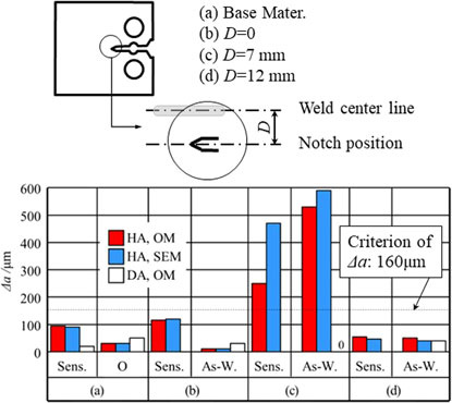
Crack propagation length, Δa, for sensitized (Sens.), O-tempered (O) and as-welded (As-W.) materials based on OM (optical microscope) and SEM (scanning electron microscope) observations. Test atmosphere: HA (humid air) and DA (Dry air).
The 5000 series non-heat-treatable Al–Mg alloys are widely used as structural members, because of excellent combination of weldability, corrosion resistance and mechanical properties. The major structural alloys of this series have been used for shipbuilding, armor plate, automobile cars, and tankage for about 50 years. Plates and sheets of 5083 alloy in O-temper are the most common materials currently used for high-speed aluminum ships and construction of liquid natural gas (LNG) tanks in LNG carriers.1) It is well known that these alloys can become susceptible to inter-granular corrosion (IGC) and inter-granular stress corrosion cracking (IGSCC) if exposed to elevated temperatures in the range of 50–200°C for extended periods of time.2–6) Since IGC and IGSCC in these alloys are caused by the precipitation of Mg-rich β (Mg2Al3) phase at grain boundaries (GBs) that takes place either during the fabrication or service, the intended heat treatment, known as sensitization, to certain combinations of time and elevated temperatures is used to examine the susceptibility of these alloys to IGC and IGSCC in laboratory level. Since the β-phase precipitates are electrochemically less noble than the aluminum matrix and hence will dissolve during subsequent exposure to a corrosive aqua-solution such as sea water, the continuity of these precipitates at the GBs increases the susceptibility of the 5000 series alloys to IGC and IGSCC.7–11) Thus, anodic dissolution of the precipitates was thought to be a mechanism for IGSCC.
Hydrogen embrittlement (HE) was proposed as another mechanism for IGSCC in Al–Mg alloys besides IGC.12–18) The hydrogen was considered to arise from anodic dissolution of the β-phase in the actual IGSCC18) or was introduced by electrolytically cathodic charging in the laboratory. Holroyd et al. recently claimed that both IGC and HE occur depending on the condition, and that humid environment plays an important role on the HE type of cracking.19,20) These features are similar to those in Al–Zn–Mg alloys,21) where humid air can be a source of hydrogen which is enough for HE through reactions indicated as eq. (1):22)
| \begin{equation} \text{2Al(s)} + \text{($3+X$)H$_{2}$O}\to \text{Al$_{2}$O$_{3}$}\cdot \text{$X$(H$_{2}$O)(s)} + \text{3H$_{2}$(g)}. \end{equation} | (1) |
We applied the humid gas stress corrosion cracking (HG-SCC) test23) to MIG welds of 5083 alloy plates in the non-sensitized condition (held at room temperature for 60d from the welding to the testing).24) The HG-SCC test was developed to make screening of the materials that are usable for high-pressure hydrogen gas container, assessing the crack propagation property in HE that may be caused by impurity water vapor inside the container, although the name includes “SCC”.25,26) We discussed the sensitivity to HE with heterogeneity of macro- and micro-structures.24,27) Main results were:
As structural materials, long-term reliability is crucial, and sensitization treatment has been used to assess long-term reliability of the alloys against SCC in laboratory level, as mentioned earlier. This treatment is presumed to be also useful to assess the resistance to HE of the base material and welded joints of 5083 alloy. So far, however, the effect of sensitization on HE for the welds of this alloy has not been well understood in terms of the different locations such as mentioned above. In this study, we will evaluate the effect of sensitization on the resistance to HE in the base and MIG-welded 5083-O materials using the HG-SCC test23) and slow strain rate tensile (SSRT) test commonly used to assess the resistance to HE easily.26,28)
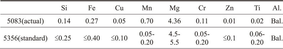
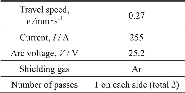
A pair of O-tempered 5083 plates with a thickness of 8 mm were subjected to MIG welding with a welding wire of 5356 alloy with a diameter of 1.6 mm. The actual and standard chemical composition of these alloys, respectively, are provided in Table 1. The MIG welding with butt joint was carried out with full penetration parallel to the plate rolling direction. The welding parameters are indicated in Table 2. The interval time between the completion of welding process and the sensitization was about 120d.
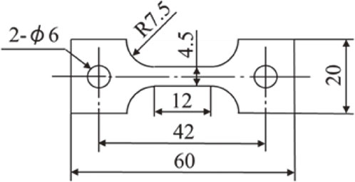
For HG-SCC test, the 8 mm thick welded plates were machined to 7 mm thickness from both sides, removing the weld crown. Like the way in the previous paper,24) compact tension (CT) test pieces were cut with four different kinds of notch locations against the weld center, and machined to the size and shape as indicated in Fig. 1. As also illustrated in Fig. 1, the notch locations were: base metal far from fusion zone (a), weld center (b), 7 mm from the weld center referred to as weld corner in the previous study24) (c), and 12 mm from the weld center regarded as HAZ (d).
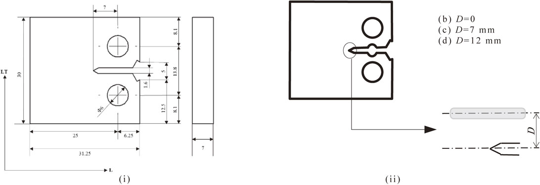
CT test piece. (i) Details. (ii) Notch position with different distances (D) from the weld center line.
For SSRT test, test pieces whose morphology and dimension are illustrated in Fig. 2 were cut from central portion in the thickness direction of welded material by a milling machine so that the weld line is perpendicular to the tensile direction.
Morphology and dimension in mm of the SSRT test piece with 1.5 mm in thickness.
The sensitization treatment was carried out both on the base and welded materials and both on the CT and SSRT test pieces for 7d at 130°C. Sensitized CT test pieces were wet-polished up to #2000, with abrasive papers and then buffing with alumina paste was performed for both sides to get mirror-finished surface. On the other hand, the SSRT test pieces with the original milled thickness of 1.5 mm were ground with abrasive paper (finally with #800) to 1 mm thickness, cleaned with 10% NaOH solution and then de-smutted with 10% HNO3 solution.
2.2 HG-SCC testThe HG-SCC test was carried out in the same way as described in the previous paper,24) based on the standard.23) In this test, a static stress intensity factor (KIApp [MPa$\sqrt{\text{m}} $]), equivalent with 0.2% proof stress (σ0.2 [MPa]) at a crack tip of 1 mm length ($\sqrt{\pi \times 0.001} \sigma_{0.2} = 0.056\sigma_{0.2}$ [MPa$\sqrt{\text{m}} $]), is kept applied to the CT test piece for the period of 30d.
The tests on sensitized base and welded materials were conducted in the following four steps:
| \begin{equation} a_{0} \geqq 1.27 \times \left(\frac{K_{\text{IApp}}}{\sigma_{0.2}}\right)^{2} {}\times 1000 \end{equation} | (2) |
| \begin{equation} V = \frac{K_{\text{IAPP}} \times \sqrt{W}}{0.032 \times E \times f(x)} \end{equation} | (3) |
| \begin{equation} f(x) = \frac{2.24 \times (1.72 - 0.9x + x^{2}) \times \sqrt{1 - x}}{9.85 - 0.17x + 11x^{2}} \end{equation} | (4) |
| \begin{equation} x = \frac{a_{0}}{W} \end{equation} | (5) |
Then, the test piece was maintained in humid air (HA) chamber with RH ≥ 90% but without dew, held for the period of 30d. Environment temperature was kept roughly constant at 25°C ± 5°C for the entire duration of the test. After completion of humid chamber retention time, the specimen was removed from humid chamber, and unloaded from fixture. The crack length, a, was determined by averaging the values measured with OM on both surfaces of the test piece. The extension of crack length, a − a0, means the progress of HG-SCC.
In this study, the local 0.2% proof stress was not largely changed by the sensitization treatment, and hence the same values as in the previous study were applied to the four kinds of specimens, (a) through (d). The sensitized base material (a) was tested also in dry environment (RH < 5%) as a reference with the same procedures as explained above in (i) to (iv).
2.3 SSRT testAs mentioned earlier, to evaluate HE characteristics conveniently, SSRT test was conducted at a low strain rate of 1.39 × 10⁻⁶ s−1, in two environments HA with RH ≥ 95% and dry nitrogen gas (DNG) at RH ≤ 5% at ambient pressure and temperature (25°C). The above strain rate was chosen because it is slow enough to detect an HE-sensitive aluminum alloy.26) The test results were compared with those obtained on non-sensitized (welded and kept at room temperature for 60d) 5083-O specimens in the previous study.24)
2.4 Microstructure observationTo obtain information on the HG-SCC path in relation to the microstructure, a separate set of CT test pieces were subjected to HG-SCC test step (i) and (ii) described in the section 2.3, ground with abrasive paper up to #2000, mirror finished by buffing with alumina paste, etched with an aqua solution of 20% HNO3 at about 75°C for about 60 s, and then observed with the SEM.
Optical microscopic images of the crack ends of the sensitized test pieces before and after HG-SCC test for 30d are shown in Fig. 3. Number of the test pieces was one for each condition. For all test pieces, crack is found to extend with the amount shown in the figure. It is obvious that the sensitivity is the highest in the position (c) referred to as weld corner that has been characterized as fusion zone adjacent to HAZ. The highest sensitivity in this position was also observed in the as-welded condition, and can be attributed to the highest Mg concentration in this position as shown in the previous study.27) Hence, the sensitization is confirmed not to change the tendency of position dependency.
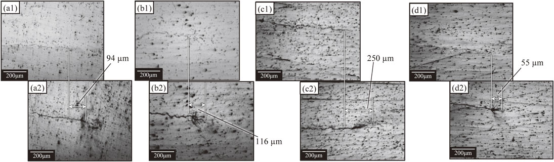
OM images of the surface of the sensitized 5083 test pieces, showing crack ends before and after HG-SCC duration. (a1) to (d1): pre-crack ends of base metal, weld center, weld corner and HAZ, respectively. (a2) to (d2): corresponding areas of the above test pieces after HG-SCC duration.
Figure 4 shows the SEM images of fractured surface of 5083 sensitized samples: base metal (a), weld center (b), weld corner (c) and HAZ (d). In the images in Fig. 4(a)–(d), and magnified images (a1)–(d1), there are areas with features different from fatigue crack propagation which can be recognized between pre-crack and post-crack. The two boundaries of this area with the pre- and post-crack areas are marked by a pair of dashed curves in Fig. 4(c) since they have a complicated shape, while they are marked with a pair of arrows both at the upper and lower sides of the images in Figs. 4(a), (a1), (b), (b1), (d) and (d1) since they are almost linear. The areas sandwiched by the pair of the boundaries can be regarded as HG-SCC surface. Thus, HE for all 5083 sensitized samples are confirmed also on the fractured surface. From the observation of fractured surface in Fig. 4, it cannot be concluded whether HG-SCC is inter-granular or trans-granular.

SEM images of fracture surfaces of the test pieces after HG-SCC test. (a1) to (d1) are enlarged images of (a) to (d), respectively.
Summary of the HG-SCC test results (average crack propagation length, Δa) of sensitized samples based both on surface (OM) and fractured surface (SEM) observations are illustrated in Fig. 5, together with those of the O-tempered and as-welded samples obtained in the previous study.24) By comparing the result of the sensitized sample (a) tested in HA with that tested in DA, the sample tested in HA is found to have much larger crack propagation length than that tested in DA. Thus, it is found that humid air has direct effect on HG-SCC progress. The HG-SCC propagation just in HA, not in an apparently corrosive environment, means HE occurs in sensitized 5083 base and welded materials. If we compare the data of sensitized samples with those of O-tempered and as-welded samples, sensitization treatment is revealed to accelerate the HG-SCC propagation in all the positions except (c). Acceleration of HG-SCC by the sensitization treatment is obviously due to precipitation of β phase along grain boundaries, and dendritic cell boundaries in fusion zone or sub-grain boundaries in the base material and HAZ.

Summary of the HG-SCC test results (crack propagation length, Δa) for the sensitized materials (Sens.) as well as the O-tempered and as-welded materials (O and As-W.) derived from the previous report,24) based on OM and SEM observations. In the present study, the data of OM are the average of those on both surfaces, while those of SEM were acquired at the middle thickness. Number of the test was one for each condition. Other than (a), no test was made in DA in the present study. The as-welded specimen (c) (As-W.) tested in DA showed no crack extension. The criterion of Δa, 160 µm, described in the test standard23) is indicated with a dotted line.
Regarding position dependency, the sensitivity is the highest in the position (c) among all the positions tested both with and without sensitization. As mentioned above, sensitization treatment enhances the HG-SCC, but is proved not to change the tendency of position dependency. Another feature that should be noted is that Δa measured with SEM is larger than that measured with OM in the position (c), which means that crack growth is faster in the interior than in the vicinity of the surface. On the other hand, the crack propagation amount in the interior is almost the same as that near the surface in the other positions. From these results, stress condition (plane strain or plain stress) affects the propagation amount only in the position (c) where overall propagation amount was far larger than the other three positions. This can be rationally understood by assuming that the KISCC (critical stress intensity factor for SCC) value of position (c) is smaller than those of the other positions, which might be caused by the smaller KIC (fracture toughness) value of position (c). In the previous study,27) the highest sensitivity in the position (c) was attributed to the highest Mg concentration in this position, but it may be also attributable to the smaller KISCC and KIC values in this position from the above discussion. The reason why the sensitization treatment seems to mitigate HG-SCC in the position (c) was not elucidated within the current study.
Further investigation using SEM on etched surface of sensitized 5083 specimens were carried out to visualize the relationship between the crack paths and grain boundaries. Figure 6 illustrates the results of the specimens (b) and (c), showing that the HG-SCC progresses mostly in trans-granular manner in the two surface specimens with a small number of inter-granular propagations as indicated by several arrows. Although the feature in the base material (a) and HAZ (d) is not shown in Fig. 6, the crack propagation path was observed to be the same as (b) and (c): mostly trans-granular with a small inter-granular fraction. There is a possibility that the crack propagates along grain boundaries inside the test piece of the position (c) where the crack propagated irregularly (Fig. 4(c)). There is also a possibility that the dendrite cell boundaries in the position (b) and (c) and sub-boundaries in the position (a) and (d) may act as crack path since these boundaries are the preferential cites for β-phase precipitation. It has been assumed that the HE crack proceeds along the precipitate/matrix interface,14) which has not been verified in this study experimentally.
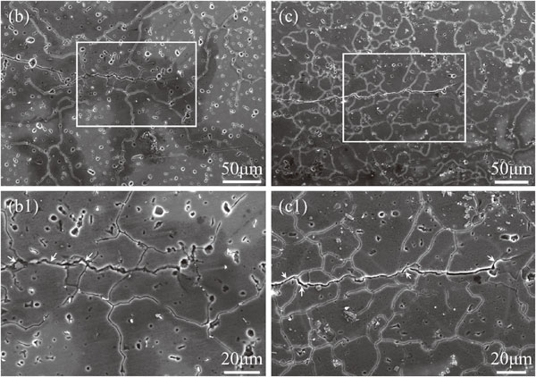
SEM images of surface crack propagation of the two specimens, (b) and (c), after HG-SCC test duration of 30 d. (b1) and (c1) are enlarged images of (b) and (c), respectively.
Stress vs. strain curves are shown in Fig. 7 both for the welded and base materials after sensitization treatment at 130°C for 7 days tested in the two environments (HA and DNG) in an SSRT condition (at 1.39 × 10⁻⁶ s−1). From this figure, it is seen that no HE occurs in either material after sensitization in terms of the reduction either in tensile strength or elongation to failure when tested in HA, which means that SSRT test is less sensitive than HG-SCC test to detect HE. The welded material shows lower strength than the base material corresponding to the lower hardness in the central portion of the weld (as per previous research results24,27)). This means that the local strain rate in the actually deformed region is faster than the nominal strain rate in the welded material, causing the incapability of hydrogen atoms to accumulate to the crack tip. This effect may be one of the causes that SSRT test is less sensitive to detect HE as pointed out previously.26) Figure 8 demonstrates the fractured surfaces of SSRT-tested pieces, where all the specimens show ductile feature, in accord to the stress vs. strain curves shown in Fig. 7.
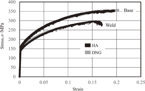
Stress vs. strain curves of the sensitized base and welded materials SSRT-tested in HA and dry nitrogen gas (DNG) environments.
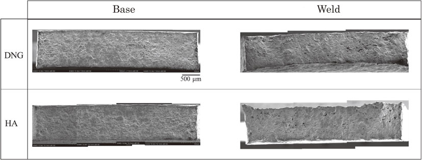
Fractured surfaces of sensitized base and welded materials SSRT-tested in HA and DNG environments.
Resistance to HE of sensitized 5083 base material as well as welded material was evaluated by means of HG-SCC test in HA using pre-cracked samples and SSRT test in HA using smooth test pieces. The results were discussed with respect to the position of the pre-crack relative to weld line and compared with those obtained for the as-welded material obtained in the previous study.
The major conclusions drawn from this study are as follows:
The authors are grateful to UACJ Corporation for their supply of the materials for all the tests. Part of the work was financially supported by The Light Metal Educational Foundation, Inc., which is highly appreciated.