Abstract
Various motor using transportation system in land-sea-air, high speed mobile terminal with 5G specification, and renewable energy storage equipment have required innovative metal rechargeable batteries compared with lithium ones. In particular, magnesium has huge potentialities as an anode material from the standpoint of its theoretical volumetric capacity superior to that of lithium. Secondly, magnesium has been one of the most abundant elements in the Earth’s crust. Moreover, the potential safety by short-circuiting evading with non-dendritic deposition of magnesium. In general, magnesium-based ribbon as an anode has been manufactured by cold rolling which requires multistage process including heat treatment. We have studied rapid liquid quenching process in order to develop low-cost manufacturing technique. On the other hand, we have focused Mg–6 mass%Al–3 mass%Ca alloy due to this unique microstructure which consist of primary crystals and intermetallic compounds along grain boundary. In addition, calcium has affected to prevent of molten magnesium burning in air atmosphere. The structural properties and surface morphology are investigated by XRD and Digital Microscope, respectively. Microstructure has been observed by FE-SEM and FE-TEM. Moreover, these electrochemical properties have been examined by constant current charge - discharge tests using 3 electrodes type cell. Mg–3 mass%Al–1 mass%Zn alloy cold rolled thin plate has been investigated as comparison. The ribbons that exhibited electrochemical properties had a fine microstructure. It is suggested that the grain refinement and dispersion of the second phase are important to improve the charge-discharge properties of Mg–Al–Ca based anode materials.
1. Introduction
The promotion of a decarbonized society is essential in order to solve global warming, which has recently been highlighted as a major problem worldwide. As a means to realize this, the development of next-generation storage battery technology using innovative technology is urgently needed. At the same time, the establishment of this technology corresponds to three of the 17 development goals for a sustainable world: 7, “Make energy clean and available to all”, 9, “Create a foundation for industrial and technological innovation”, and 13, “Take concrete measures to combat climate change. The current situation surrounding us is that the use of lithium-ion batteries (LIB) in electric vehicles and portable devices is expanding, but there are problems: the required performance (especially the electrical capacity per volume) is beginning to reach its limits, and there are concerns about the uneven distribution and depletion of the raw materials used in batteries, as well as safety. The following is a comparison of candidate elements in terms of material selection for metal anodes for next-generation storage batteries.
-
1.
Valence: alkaline earth > alkali
-
2.
Clarke number: Ca > Na > K > Mg > Rb > Ba > Sr > Li
-
3.
Melting point: Ca > Sr > Ba > Mg > Li > Na > K > Rb
-
4.
Electric potential: Li > K = Rb > Ba > Sr > Ca > Na > Mg
-
5.
Density: Li < K < Na < Rb < Ca < Mg < Sr < Ba
-
6.
Price: Mg < Na < Ca < K < Li < Ba < Sr < Rb
From the above results, we have narrowed down our focus to lithium, magnesium and calcium, and summarized their various characteristics in Table 1.1,2) Calcium is a promising alternative to lithium among alkaline earths, but its price is a bottleneck. On the other hand, magnesium is inferior in terms of electric potential, but it is inexpensive, and there is no concern about depletion of raw materials.
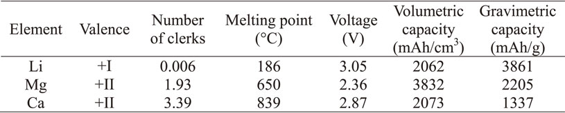
Table 1 Properties comparison of potential anode materials.
In recent years, as the demand for thinner products has increased, light metals with high rigidity, i.e., titanium, aluminum and magnesium, have been attracting attention in place of plastic, which has been widely used in the past. In particular, magnesium alloy has a density of about 1.8 Mg/m3, and is the only light material among practical metals that is comparable to plastic. Furthermore, the raw materials for magnesium alloys are inexhaustible in seawater and are non-toxic, so they are expected to be the most promising lightweight materials. In addition, as a result of the development of smelting and dissolution technologies, it has been confirmed that there are almost no practical problems with the ease of combustion and low corrosion resistance, which had been concerns in the past.3) Pure Mg and AZ31 (Mg–3 mass%Al–1 mass%Zn) alloy, which are easily available as rolled materials, have been used for Mg metal rechargeable batteries. In addition, studies4,5) using insertions on Bi, Sb, and their alloys have been investigated for Mg ion rechargeable batteries. When intermetallic compounds are used as the anode active material, both cell voltage and capacity decrease, which is disadvantageous from the viewpoint of energy density, but the utilization rate of the active material is almost 100%, and it is considered that more practical electrode design is possible.6) On the other hand, for magnesium alloys, polycrystalline magnesium alloy materials consisting of fine grains with 0.3 at% of very small amounts of different elements (Al, Ag, Bi, Ca, Li, Mn, Pb, Y, Zn) were prepared, and their electrochemical properties were evaluated. It was reported that the Mg–Ca alloy material showed three times the current density of the pure Mg material and continued extremely stable dissolution and precipitation behavior for more than 80 cycles.7) Furthermore, the effects of these trace elements and tilted grain boundaries on electrochemical activity have been investigated using a first-principles DFT model.8) Kurihara found that CZ31 (Mg–3 mass%Cu–1 mass%Zn), in which Cu was added instead of Al in the conventional AZ31, can apply about 6 times higher current.9) Other materials such as Sn alloys, biphasic Bi–Sn alloys, Ti composite oxides, nanostructured metal oxides, B clusters, and graphene have also been investigated.10) However, as with the reason for selecting Mg as the active material, it is necessary to take into consideration the raw materials that should be added or used as the matrix and the low cost of synthesis.
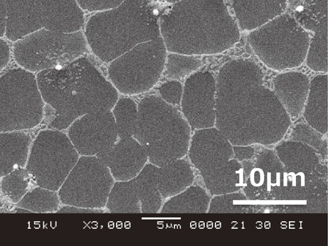
During the development of inexpensive heat-resistant Mg–Al alloys by metal injection molding (thixomolding), the authors experienced that the addition of Ca, which is effective for creep resistance, resulted in significant deterioration of corrosion resistance.11) The corrosion rate and the maximum pitting depth after 100 h of salt spray test are shown in Fig. 1, pitting corrosion through a thickness of 2 mm was observed in the alloy with 3% Ca. The typical microstructure of the alloy is shown in Fig. 2, where the 5–10 µm primary Mg was covered by eutectic compounds, which suppressed the creep deformation at the grain boundaries.12) Furthermore, calcium has a fire-retardant effect on the molten magnesium alloy and its products, and is an additive element that has a small environmental impact in terms of both production and use. Therefore, we decided to focus on Mg–Al–Ca alloys, especially Mg–6%Al–3%Ca, as the material for the anode of magnesium rechargeable batteries.

On the other hand, high-pressure casting such as die casting is the most common method, and the mass production of expanded materials is gradually increasing. As for powders and ribbons using the rapid solidification method, the number of applicable products is expected to increase in the future. The product form of the anode material, which is the subject of this study, is assumed to be a ribbon of 0.1 mm level, and cold rolling is a common mass production method for metallic materials. The crystal structure of Mg is hcp. Therefore, we set the target of ribbon at 0.2 mm or less, and focused on the liquid quench solidification method, which can produce ribbon directly from molten metal without undergoing plastic working of the solid phase. Furthermore, we focus on the single-roll quench solidification method, which is an alternative to rolling and has the potential for cost reduction, and examine the possibility of its realization.
From the above point of view, this study focused on magnesium as an anode material for innovative metal rechargeable batteries, which are desired in various electric transportation systems on land, sea and air, mobile information and communication devices, renewable energy storage devices, etc., and investigated the method and material to fabricate ribbon of 0.1 mm thickness at low cost. As a result, a single-roll liquid quenching method was selected and Mg–Al–Ca alloy ribbons with fine crystal grains were fabricated, and the constant-current charge-discharge characteristics were evaluated using a three-electrode method. The relationship between the anode surface morphology and crystal structure was investigated.
2. Experimental Procedure
2.1 Materials and process
2.1.1 Materials
High-purity magnesium (99.9%), high-purity aluminum (99.9%) and Mg–30 mass%Ca alloy ingots were used as starting materials, cut and weighed to obtain Mg–6 mass%Al–3 mass%Ca, inserted into a crucible made of SUS430, and melted in an electric furnace at 680°C with Ar gas flow. After melting in the furnace, the molten metal was cast into a cylindrical mold at a temperature of 630°C and a mold temperature of 200°C. The round bars were extruded with an extrusion ratio of 7.06, an extrusion temperature of 350°C, and a ram speed of 1 mm/s using a 400t vertical hydraulic press, and were cut into 10 mm thick pieces to be used as the quenched and solidified raw materials.
2.1.2 Process
Figure 3 schematically shows the internal structure of the single-roll liquid rapid solidification apparatus. Using a 20 mm wide × 200 mm diameter oxygen-free copper cooling roll without cooling water, cut materials were inserted into a crucible with a 10 mm wide nozzle made of SUS430, heated and melted by a high-frequency coil, and then sprayed with Ar gas onto a high-speed rotating roll to produce ribbons. The production conditions were four factors: peripheral speed of the cooling roll, gap distance, melting/injection temperature, and injection pressure, and experiments were conducted at each level shown in Table 2.
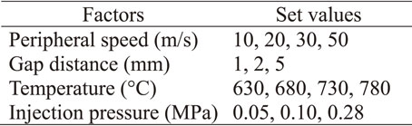
Table 2 Manufacturing conditions of ribbon specimens.
For characterization, we measured the thickness using a micrometer, observed the surface using a digital microscope, analyzed the chemical composition using inductively coupled plasma atomic emission spectrometry (ICP-AES), identified the crystalline phase using X-ray diffraction (XRD: Cu-Kα), and observed the microstructure using field emission scanning electron microscope/transmission electron microscope (FE-SEM/FE-TEM). The redox behavior of magnesium metal as an electrochemical property was evaluated by constant-current charge-discharge tests using a three-electrode beaker cell.13) The working electrode (anode) was a ribbon sample (3 × 4 mm) cut into specimens, the counter electrode (cathode) was an activated carbon electrode with an aluminum foil current collector, the reference electrode was a high purity magnesium foil, and the electrolyte was a mixture of the cyclic acid anhydride succinic anhydride: SA and magnesium bi fluoro methane sulfonyl amide: MgTFSA2. MgTFSA2 dissolved in dimethylacetamide (DMA) was used as the electrolyte. In the constant current charge-discharge test, the current value was increased with the number of cycles, and the potential change of the magnesium alloy was measured. AZ31 rolled material with a thickness of 0.2 mm was used as a comparison material. The electrolyte preparation and cell assembly were carried out in a glove box with an Ar gas circulation and purification system that controlled the oxygen and moisture content to less than 1 ppm, and the constant current charge-discharge test was carried out in a thermostatic bath controlled at 35°C.
3. Results and Discussions
3.1 Chemical composition analysis
Table 3 shows the results of chemical composition analysis of the extrudate and the ribbon. Although the Al content was lower than the target at 5.3%, there was no change in composition before and after quench solidification. Mn, which improves corrosion resistance in Mg–Al alloys, was not added. The amounts of impurities such as Fe and Cu, which reduce corrosion resistance, were also low enough.

Table 3 Chemical composition analysis result from ICP-AES.
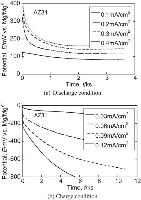
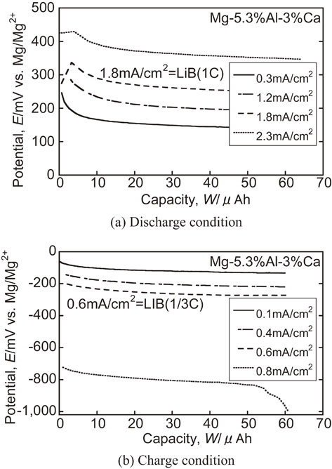
The effects of peripheral speed of the cooling roll on the constant current charge-discharge characteristics as electrochemical properties are shown in Fig. 4. The electrochemical properties of the Mg–5.3%Al–3%Ca alloy ribbon with optimized manufacturing conditions and the AZ31 rolled specimen as a comparison material are shown in Fig. 5 and Fig. 6. On the other hand, the Mg–5.3%Al–3%Ca alloy ribbon showed only a slight increase in overvoltage with increasing current value, indicating that its charge-discharge characteristics were superior to those of the AZ31 rolled material. Furthermore, Fig. 7 shows the charge-discharge characteristics when the current value load is increased. Stable redox behavior was observed even at 20 times the current density higher than that of AZ31 indicating a capacity the current density comparable to that of LIB. The plateau potential was obtained even at 20 times the current density higher than that of AZ31.
3.3 Shape characteristics
Photographs of both sides appearance of the ribbons at different peripheral speeds is shown in Fig. 8. The ribbon had visible unevenness, while the cooling roll side was relatively smooth. However, as shown in Fig. 9, there was no significant change in surface area at peripheral speed. The effects of peripheral speed of the cooling roll on the thickness of the ribbon are shown in Fig. 10. Within the scope of the present experiment, the most prominent effect on the thickness of the ribbon is the peripheral speed of the cooling rolls, and the thickness decreases with increasing peripheral speed, reaching a thickness of less than 0.2 mm above 30 m/s, suggesting that the cooling rate increases with decreasing thickness. At the same time, it was found that a peripheral speed of 30 m/s was necessary to maintain the uniform shape of the ribbon.
3.4 Crystal structure
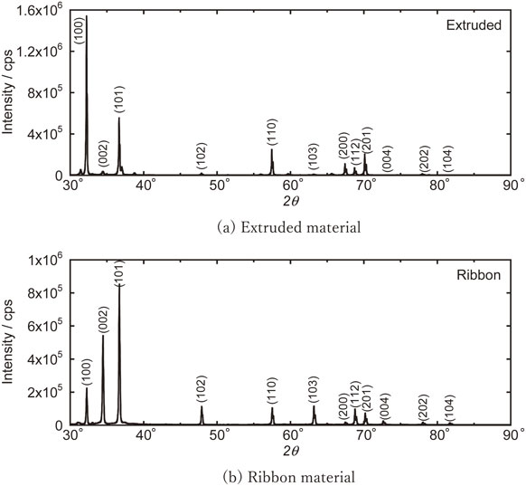
Figure 11 shows the crystal phase identification results of the extruded material (extrusion orthogonal direction) and ribbon (flow direction) by XRD. The lattice parameter of α-Mg was estimated by correcting the systematic error of the optical system using Si powder as an external standard sample, and the results are summarized in Table 4 with the literature values.13) The crystallite size was calculated from the integrated width of each diffraction peak by the Halder-Wanger method.
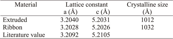
Table 4 Lattice constants and crystallites calculated from XRD analysis.
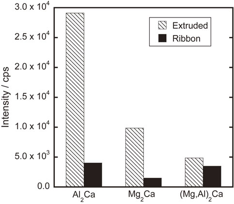
On the other hand, as shown in Fig. 12, the crystalline phases formed in this alloy composition are randomly oriented Mg (A3-type hcp phase), Mg2Ca (C14-type hcp phase), Al2Ca (C15-type fcc phase), and (Mg, Al)2Ca (C36-type hcp phase), as in the case of Thixomolding, which is one of the high-pressure casting methods.11,12) From the diffraction peaks of the three intermetallic compounds,14,15) their abundance ratios were calculated and summarized in Fig. 13. It is characteristic that the ratio of the stable phase Al2Ca, which was crystallized after extrusion, decreased significantly during rapid solidification.

The reason why the lattice parameter of the extruded material is larger than the literature value may be due to the solid solution of Al, which has a smaller atomic radius than that of Mg. The fact that the lattice parameter is even smaller in the thin zone is presumably due to the fact that the diffusion of Al to the grain boundary is delayed due to the increased cooling rate caused by rapid solidification, and the crystallization of the stable phase, Al2Ca, is reduced, resulting in supersaturated solid solution in Mg. This is also consistent with the fact that the amount of Al2Ca in the ribbon is lower than that in the extruded material. On the other hand, the crystalline size of these materials were approximately same level.
3.5 Microstructure
The surface observation results of the Mg–5.3%Al–3%Ca ribbon fabricated under the optimum conditions by FE-SEM are shown in Fig. 14. On the surface of the cooling roll side, plate-like elongated grains perpendicular to the longitudinal direction of the ribbon were observed. On the free surface side, relatively equiaxed grains at the submicron level were observed. A similar microstructure was also observed partly on the cooling roll side, and depressions were observed at and near the grain boundaries in this equiaxed grain area. The reason for this microstructure is thought to be due to the formation of eutectic compounds in the final solidification zone and solidification shrinkage.

The grain size of the matrix phase on the cooling roll surface was larger than that on the free surface side, but a high density of the second phase was observed at the grain boundary. According to the first-principles calculations by Tian et al.,8) the discharge reaction of Mg basically depends on the increase of the interface. The same effect may be obtained by increasing the hetero-interface through the introduction of eutectic compounds in this alloy, and these are effective to improve the charge-discharge properties.
4. Conclusion
We focused on Mg as an anode material for next-generation metal rechargeable batteries to achieve carbon neutrality, and investigated inexpensive combinations to achieve social implementation as soon as possible. As a result, the production of Mg–Al–Ca alloy by a single-roll rapid solidification system was found to be promising, and by optimizing the production conditions (peripheral speed of cooling rolls, gap distance, melting/injection temperature, and injection pressure), it was found to have superior charge-discharge characteristics compared to AZ31 rolled material, which is a general-purpose alloy, and to have a current density about 20 times higher than that of LIB. It was found that a current density comparable to that of LIB could be obtained. The mechanism is thought to be attributed to the increased solidification rate due to the large cooling rate, which results in fine crystals, as well as the dense secondary phase at the grain boundaries, which increases the heterophanes interface.
In the future, we will further design the composition and anode structure, and study the low-cost manufacturing conditions to evolve this material technology as a material that can be attributed to the early realization of the SDGs.
Acknowledgments
This work was supported by THE HOKURIKU BANK Grant-in-Aid for Young Scientists. And we thank Mr. S. Okita, who is a technical staff in the Faculty of Engineering at the University of Toyama, for making the Mg–Al–Ca extruded material.
REFERENCES
- 1) R. Maruyama: Mie Prefectural Industrial Research Institute Research Report 39 (2015) 97–101.
- 2) F. Sagane: Chem. Eng. 64 (2019) 803–810.
- 3) T.T. Tsukeda and K. Saito: J. JILM 47 (1997) 298–305. doi:10.2464/jilm.47.298
- 4) M. Hattori, K. Yamamoto, M. Matsui, K. Nakanishi, T. Mandai, A. Choudhary, Y. Tateyama, K. Sodeyama, T. Uchiyama, Y. Orikasa, Y. Tamenori, T. Takeguchi, K. Kanamura and Y. Uchimoto: J. Phys. Chem. C 122 (2018) 25204–25210. doi:10.1021/acs.jpcc.8b08558
- 5) T.S. Arthur, N. Singh and M. Matsui: Electrochem. Commun. 16 (2012) 103–106. doi:10.1016/j.elecom.2011.12.010
- 6) M. Matsui: Denki Kagaku 86 (2018) 298–304. doi:10.5796/denkikagaku.18-FE0030
- 7) T. Mandai and H. Somekawa: Chem. Commun. 56 (2020) 12122–12125. doi:10.1039/D0CC05373B
- 8) H.-K. Tian, R. Jalem, M. Matsui, T. Mandai, H. Somekawa and Y. Tateyama: J. Mater. Chem. A 9 (2021) 15207–15216. doi:10.1039/D1TA02419A
- 9) H. Kurihara and M. Inamoto: Saitama Industrial Technology Center Research Report 17 (2019) 53–56.
- 10) F. Bella, S.D. Luca, L. Fagiolari, D. Versaci, J. Amici, C. Francia and S. Bodoardo: Nanomaterials 11 (2021) 810–838. doi:10.3390/nano11030810
- 11) T. Tsukeda, R. Uchida, M. Suzuki, J. Koike and K. Maruyama: Proceedings of the Second Osaka International Conference on Platform Science and Technology for Advanced Magnesium Alloys 2003, (Trans. Tech. Publications, Switzerland, 2003) pp. 439–444.
- 12) A. Shibata, M. Suzuki, T. Tsukeda, K. Saito and K. Maruyama: J. Japan Inst. Met. 70 (2006) 968–974. doi:10.2320/jinstmet.70.968
- 13) Y. Kojima: Handbook of Advanced Magnesium Technology, (Kallos Publishing, Tokyo, 2000) p. 55.
- 14) D. Kevorkov, M. Medraj, J. Li, E. Essaduqi and P. Chartrand: Intermetallics 18 (2010) 1498–1506. doi:10.1016/j.intermet.2010.03.038
- 15) A. Suzuki, N.D. Shadock, J.W. Jones and T.M. Pollock: Scr. Mater. 51 (2004) 1005–1010. doi:10.1016/j.scriptamat.2004.07.011