Abstract
The effect of formic acid surface modification process on the bond strength of the solid-state bonded interface of tin and nickel was investigated by SEM observations of fractured surfaces and interfacial microstructures. Tin and nickel surfaces were modified by boiling in formic acid for 600 s. Diffusion bonding was performed at bonding temperatures of 393–493 K under a load of 7 MPa (bonding time for 1.8 ks). The bond strength increased with increasing bonding temperature irrespective of surface modification process. As a result of surface modification process, bonded joints were obtained at a bonding temperature 70 K lower than that required for non-modified surfaces used, and the bond strength was comparable to that of the base metal. When the surface modification process was not applied, the fracture mode was brittle. As the bond strength increased with increasing bonding temperature, the fracture mode changed to ductile. With surface modification process, this tendency was observed at a bonding temperature 70 K lower than without it. The results suggest that these changes in the fractured surface between tin and nickel were accompanied by expansion of the metal-to-metal contact area, which contributed to the increase in bond strength.

1. Introduction
As a method for manufacturing electronic components that are becoming smaller and smaller, a solid-state bonding method is being studied as an alternative method to soldering, and is being put into practical use. Meanwhile, in recent years, the mounted electronic components are often made of heat-sensitive resin (e.g., optical components) or low mechanical strength (e.g., electromechanical components). These electronic components must be bonded at low bonding temperatures and low bonding loads. However, it has been pointed out that an oxide film and a processed layer exist on the actual bonding surface, and these inhibit solid-state bonding.1–3) Therefore, in order to form a connection portion having high bonding strength, it is necessary to remove the oxide film on the bonding surface. Therefore, a method for removing a surface oxide film using ultrasonic vibration4–7) or a plasma processing8–11) has been studied. In our previous studies, we have applied surface modification treatments using organic acids to various bonding interfaces and investigated improvements in bond strength. For example, it was found that by modifying the Cu/Sn bonding surface with formic acid, it was possible to fabricate a base metal-breaking joint in Sn at a bonding temperature as low as 40 K.12) It was found that by modifying the Cu bonding surface with formic acid or citric acid, it was possible to fabricate joints with the same bonding strength as those without treatment, even at a 150 K lower bonding temperature.13) It was found that the modification treatment using formic acid on the bonding surface of SUS304 stainless steel improved the bonding strength to about twice that of the case where no treatment was applied.14) It was found that the bonding strength was greatly improved by inserting a high-purity Al sheet with a formate film at the bonding interface between pure Ti.15) Furthermore, it was found that the bonding strength of A6061 aluminum alloy and high-strength steel sheet was greatly improved by applying an acetate film to the aluminum alloy side before solid phase bonding.16)
In recent years, nonelectrolyte Ni–P plating has come to be used on the copper wiring of print-wiring boards to control the formation of a brittle intermetallic compound layer at the interface between the solder and copper wiring. Nonelectrolyte Ni–P plating has attracted attention as an UBM (Under Bump Metallization) process because the rate of reaction with solder is slow, and numerous studies have been conducted on the bond interface and its mechanical properties in response to the operating environment (e.g., high temperature). For example, R. Labie et al. found that a Ni layer at the Sn/Cu junction interface can suppress the growth of a compound layer composed of Cu and Sn.17) J. Shen et al. discussed that the addition of Ni in the solder can suppress the growth of a compound layer at the interface between the Ni and Sn–3.5Ag solder joint.18) M. Mita et al. also compared the growth of intermetallic compound layers at the interface between Sn and Ni and between Sn and Ag, Cu, and Au.19) In addition, C. Y. Lin et al. discussed the reaction kinetics between Ni and various eutectic solders.20)
In this paper, to decrease power consumption and to control the formation of an intermetallic compound, we examine the effect of formic acid modification on the bond strength between tin (the main element of solder) and nickel (the principal ingredient of UBM). Therefore, we perform solid-state bonding of tin and nickel after surface modification, and examine the bond strength and interfacial microstructure of the obtained joints.
2. Experimental Procedure
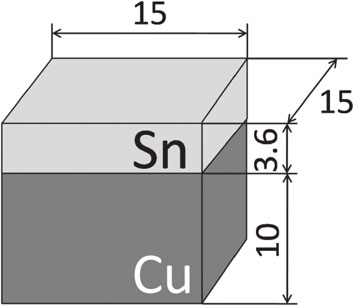
The specimen to be bonded was a block 15 × 15 × 5 mm3 cut from a 99.9% tin ingot. As shown in Fig. 1, a copper block was bonded to the tin block for the convenience of the strength test of joints. The bonding conditions were as follows: the bonding surfaces of Cu and Sn were mechanically polished with SiC paper (#4000), the bonding pressure was 2 MPa, the bonding temperature was 493 K, and the bonding time was 2.7 ks in a vacuum chamber (1.3 × 10⁻¹ Pa). The bonding surface of the tin (15 × 15 mm2) was finished by electrolytic polishing in a solution containing 85% ethyl alcohol, 10% ethyl glycol monobutyl ether, and 5% perchloric acid. The bonding surface of the nickel (99.6%, 15 × 15 mm2) was finished by grinding on SiC paper (#4000).
Formic acid surface modification process was performed by boiling nickel and tin in formic acid for 60–1200 s at 374 K. The formic acid (98.0%) was purchased from FUJIFILM Wako Pure Chemical Corporation. To specify what chemicals are formed on the surface after this treatment, the nickel and tin surfaces were identified by X-ray diffractometer (XRD: Rigaku RINT2100V/PC) with CuKα radiation working at the voltage of 32 kV, anodic current of 20 mA, the beam incident angle of 5°, and scanning rate of 0.02°/s, and X-ray photoelectron spectrometer (XPS: Shimadzu/Kratos AXIS-HS) with monochromatized X-ray excitation of the AlKα line. FT-IR analysis was performed to identify the type of compound on the treated Ni surface. In addition, in order to carry out nanoscale depth measurement, the grazing-angle incidence reflection-absorption infrared (GIRAS-IR) spectroscopy was used. Bonding was started within 180 s to avoid moisture absorption and surface oxidation. The diffusion bonding is performed in a vacuum chamber using following conditions, 7 MPa for bonding load, 1.8 ks for bonding time and 393∼793 K for bonding temperature (T). The bonding pressure was applied before heating the sample until the bonding time ended. The temperature raising rate was constant at 0.35 K/s.
After diffusion bonding, the specimen was cut into three pieces for the strength test and observation of metal microstructure at the bonded interface. In order to observe the cross-sectional metallographic structure of the joint interface, test pieces were prepared according to the following procedure. The test piece was mechanically polished using SiC paper (up to #4000) and then buffed with diamond paste (1 µm). Subsequently, the buffed surface was etched with a solution containing 3% hydrochloric acid and 97% ethyl alcohol to reveal a metallographic structure. The metallographic structure was observed using scanning electron microscope (SEM: Shimadzu SSX-550) and energy-dispersive X-ray spectroscopy (EDX: Shimadzu SEDX-500).
The tensile strength of the joint was evaluated by a tensile test. The number of tests for each condition is 4. The tensile test was carried out at room temperature and at a speed of 0.017 mm/s in the direction perpendicular to the bonding interface. The test piece for the strength test was cut out from the joint so as to have a cross-sectional area of 3 × 3 mm2. After strength test, the fractured surfaces were observed using SEM.
3. Experimental Results
3.1 Surface modification effect on tensile strength
In order to investigate the effect of the surface modification treatment on the tensile strength, the bonding was performed with the bonding temperature set to 423 K and the modification time changed to 0.06–1.2 ks. Figure 2 shows the effect of surface modification treatment time on the tensile strength of the joint. Macro-photographs of the fracture surface after tensile testing are also shown in the figure. Tensile test results showed that the joints could not be joined without the surface modification treatment, but with the surface modification treatment, all joints exceeded the base metal strength of the tin at any treatment time. Macroscopic observation of the fracture surface after tensile testing showed that chisel point-type fractures occurred in the Sn, not at the interface between Sn and Ni, until the surface modification treatment time of 0.6 ks. However, when the surface modification treatment time was too long, such as 1.2 ks, areas of Sn/Ni interface fracture were observed. The cause of the interface rupture is thought to be that the metal salt film was formed thickly due to the long surface modification time and did not completely thermally decompose during bonding, resulting in failure to achieve adhesion between the metal atomic surfaces. Therefore, 600 s was designated as the optimum modification time to avoid the irregularity of surface modification.

Figure 3 shows the relationship between the bonding temperature and the tensile strength of the joint. In order to show the effect of the surface modification treatment, the case without the treatment is also shown in the figure. The tensile strength tended to increase as the bonding temperature increased, regardless of whether surface treatment was performed or not. In addition, it was found that when the surface modification treatment was applied, a joint having a tensile strength equivalent to that of the base metal of Sn was obtained at a joining temperature 80 K lower than that when the surface treatment was not applied. Moreover, when the surface was not modified, the joint broke in the bond interface although the bonding temperature was just below the melting point of tin. In contrast, when the surface was modified, the joint was observed to break in tin at the bonding temperature of 423 K. At a bonding temperature of 493 K, the tensile strength of the joint was higher than the base metal strength of tin (about 12 MPa) when the surface was not modified. This may be due to plasticity constraint effects of copper and nickel on tin.

To examine the factors determining fracture at the bond interface, the area of the fractured surface was observed with SEM. The results are shown in Figs. 4 and 5. These figures show the SEI images and the elemental maps of nickel on the fractured surfaces of the tin side measured with an EDX (Energy Dispersion X-ray spectrometer). As shown in Fig. 4, when bonded at 473 K without surface treatment, many light-colored particles with a square shape of 1 µm in diameter were observed on the smooth fractured surface of the nickel. On the other hand, a smooth fractured surface and numerous pits reflecting the density and size distributions of particles on the nickel side were observed on the tin side. This suggests that the particles which are grown from nickel to tin. When the bonding temperature was raised to 493 K, light-colored particles were hardly observed and planar deposits were observed on the fracture surface on the Ni side. It is guessed that this planar deposit was formed by the light-colored particle growing up parallel to a bond interface.


As shown in Fig. 5, when the bonding surface was modified, a clear straight polishing mark was observed on the fractured surface on the Ni side. However, at the bonding temperature of 393 K, Sn did not adhere to the fracture surface on the Ni side, while pits of 1 µm or less in diameter and projections of about 2 µm in diameter were observed on the tin side (white circled area). These pits and projections were not observed on the tin surface immediately after surface modification. As will be described later, tin formate is thermally decomposed by heating. Therefore, it is considered that the formation of these irregularities is due to the precursor reaction of tin formate by heating during bonding process. Moreover, at the fractured surface of the nickel side, there were dark-colored spots whose distribution density corresponded to that of the projections observed on the tin side. This suggests that the spots were observed because intimate contact between tin and nickel was not achieved.
When the bonding temperature is raised to 413 K, polishing marks were rarely observed on the nickel side, whereas numerous deposits of 2 µm or less in size were observed. Moreover, a portion of the deposits exhibited a ductile fracture mode which lengthened to be sharp. Almost no pits were observed on the tin side fracture surface, and the fracture morphology changed to a ductile fracture surface with tier ridges. In order to investigate the composition of the deposits and the effect on the bond strength, elemental mapping measurement of the fracture surface after the tensile test was performed using EDX. The mapping analysis results are shown on the right side of Figs. 4 and 5. The area of Ni detected from the fracture surface on the tin side increased as the bonding temperature increased, regardless of whether or not the surface modification treatment was applied. The bonding temperature at which Ni was detected from the fracture surface on the tin side coincided with the temperature at which the bonding strength began to increase. In addition, the bonding temperature at which Ni was detected on the fracture surface on the tin side was reduced by about 80 K by subjecting the surface modification treatment. Therefore, as will be described later, it is considered that the bonding strength is improved by the contact between the metal surface of tin and nickel even at a low bonding temperature. Moreover, the ductile fracture mode is observed only when the surface was modified. It is thought that this reason is because almost none of the thick intermetallic compound was formed because the bonding temperature was low.
3.2 Observation of bond interface
By observing the microstructure of the bonding interface using SEM, the reason why the tensile strength increased as the bonding temperature increased was investigated. The observation results are shown in Figs. 6 and 7. In addition, these figures show the results of line analysis of nickel and tin in the dotted line in the SEM images. The case without surface modification is shown in Fig. 6. At the bonding temperature of 473 K as shown in Fig. 6(a), gaps were observed between the bonding surfaces. When the bonding temperature was increased by 10 K, as shown in Fig. 6(b), the width of the voids decreased, and the bonded interface became unclear due to reaction diffusion through the nickel-tin interface. When the bonding temperature was raised to 493 K as shown in Fig. 6(c), the nearly linear bonded line was rarely observed; instead, there was a smooth irregularity. At the boundary, a continuous layer of about 2 µm in thickness, in which the contrast differs from other areas, was observed. This layer may similarly reflect the sectional microstructure of planar deposits observed on the fractured surface (see Fig. 4).

From these observations, a layer in which the contrast differs from other areas is observed when the bonding temperature is 483 K or more, corresponding to the bonding temperature region where the bond strength of the joint is increased. A line analysis at the bond interface was performed using EDX to examine the elemental distribution. At bonding temperatures of 453–483 K, an intermetallic layer of Ni–Sn compound was not visible at the bond interface (see Figs. 6(a) and 6(b)). When the bonding temperature was raised to 493 K as shown in Fig. 6(c), nickel was detected in a layered area, although tin was not detected on the nickel side. This suggests that the layer observed in Fig. 6(c), in which the contrast differs from other areas, is an intermetallic compound formed by the diffusion of nickel and tin.
In cases where the surface was modified at the bonding temperature of 393 K as shown in Fig. 7(a), gaps between nickel and tin, apparently without any contact, were observed in many areas interspersed among areas where nickel and tin made contact for several µm. These widths of intimate contacts and the intervals between such contacts closely corresponded to the distribution density of the deposits observed on the fractured surface of the tin side (see Fig. 5). From these observation results, it was inferred that a brittleness fracture is caused because the contacting process was imperfect, and the tensile strength of the joint decreased. When the bonding temperature is raised to 413 K as shown in Fig. 7(b), the gaps between nickel and tin observed at 393 K or less were hardly observed, and intimate contact was achieved throughout the bond interface. The range of bonding temperatures where these changes take place corresponds to the temperature where the tensile strength rises rapidly (see Fig. 3). This suggests that the intimate contact between nickel and tin greatly contributes to the improvement of the tensile strength. On the other hand, at the bonding temperature of 423 K, the bonded line became indistinct (Fig. 7(c)). In addition, the joint fractured not at the bond interface but in tin only when the surface was modified at the bonding temperature of 423 K. This observation suggests that the reaction of nickel and tin occurred after the contacting process was finished, presumably yielding joints fracturing in tin. A line analysis at the bond interface was performed to examine elemental distributions. At bonding temperatures of 393–423 K, no notable diffusion of nickel and tin was detected. Therefore, it is possible to obtain high-tensile-strength-joints by formic acid surface modification without forming a remarkable diffusion layer.
4. Discussion
It is known that exposure of nickel and tin to the atmosphere causes immediate coverage with an oxide film. Further, it is well known that the natural oxide film hinders the increase in bonding strength. It is known that tin formate and nickel formate are produced by exposing a base material containing these oxide films to formic acid.12–16,21–24) These formation reactions are shown by the following chemical formulae (X = Ni, Sn):
| \begin{equation}
\text{X} + \text{2HCOOH} \to \text{X(HCOO)$_{2}$} + \text{H$_{2}{\uparrow}$}
\end{equation}
| (1) |
| \begin{equation}
\text{XO} + \text{2HCOOH}\to \text{X(HCOO)$_{2}$} + \text{H$_{2}$O${\uparrow}$}
\end{equation}
| (2) |
| \begin{equation}
\text{XO$_{2}$} + \text{2HCOOH}\to \text{X(HCOO)$_{2}$} + \text{H$_{2}{\uparrow}$} + \text{O$_{2}{\uparrow}$}
\end{equation}
| (3) |
To examine the surface properties of nickel and tin in samples made under the processing conditions used in this study, X-ray diffraction analysis was performed (incident angle: 5°, 2θ scan). The results are shown in Fig. 8. From the X-ray diffraction pattern of the tin surface, tin (II) formate was observed in addition to tin. This pattern of change was not observed for the nickel surface. This suggests that tin (II) formate is generated by modification of the tin surface, and that nickel (II) formate is not observed on the nickel surface because the formate either is not generated or is too thin. Differential scanning calorimetry measurements (DSC: SII Seiko instrument DSC6200) were performed to investigate the thermal decomposition behavior of nickel and tin formate formed on the bonded surface. Specimens for measurement were prepared by boiling 10 µm foil for nickel and 7 µm foil for tin in formic acid. The measurement was performed at the temperature raising rate of 0.033 K/s. From the DSC measurement results in Fig. 9, no peak was detected from nickel, but in tin, an exothermic peak was detected in the bonding temperature range used in this study (425–493 K). It is a result of proving the generation of tin (II) formate that the exothermic reaction was detected in this temperature. In our previous study, tin oxide particles (SnO2, approximately 10 nm in diameter) precipitated in the bonded interface of tin were observed at the bonding temperature of 403 K or more.1,2) Therefore, it is inferred that a precursory phenomenon unaccompanied the exothermic reaction occurred. In fact, the temperature range almost corresponds to the range of bonding temperatures at which the fractured surfaces change from a brittle to a ductile fracturing mode. Furthermore, it is known that tin formate is thermally decomposed in the metallic tin, carbon dioxide, and hydrogen at 423 K according to the following reaction:25)
| \begin{equation}
\text{Sn(HCOO)$_{2}$}\to \text{Sn} + \text{2CO$_{2}{\uparrow}$} + \text{H$_{2}{\uparrow}$}
\end{equation}
| (4) |
We infer that the rapid rise in the calorific value at about 423 K was an exothermic reaction according to decomposition of tin (II) formate. Therefore, like the case that bonded Sn/Sn, the tensile strength increased as a result that the atomic planes of tin and nickel except the oxide particle were able to adhere.
In order to investigate the chemical changes on the surface of nickel boiled with formic acid for 600 s, it was analyzed using XPS and GIRAS-IR. Survey XPS spectra obtained from non-modified and modified samples are shown in Fig. 10. Both spectra exhibit characteristic XPS and Auger spectra of O, C, Ni, and Si elements, whereas the O1s XPS spectrum of the modified sample has a higher intensity than that of the non-modified sample, and the Ni2p XPS spectrum of the modified sample has less intensity than that of other samples.

Precise deconvoluted element XPS spectra of O1s, C1s, and Ni2p for the samples are shown in Fig. 11. The deconvoluted component of the O1s spectrum at a peak of 530.1 eV is characteristic to oxygen ionically bonded to metal elements. This is observed in the spectrum of the non-modified sample, but not in that of the modified sample. This result suggests that the nickel oxide layer at the surface of the sample is removed by surface modification. Furthermore, the deconvoluted C1s spectrum of the modified sample has a significant component at 289.1 eV, which is characteristic to carbon elements at carboxyl groups such as in formic acid. The deconvoluted Ni2p spectrum of the non-modified sample shows a main peak at 852.6 eV characteristic to metal-state Ni elements, as well as peaks characteristic to NiO and Ni2O3 components at 853.9, and 855.9 eV, respectively. However, the deconvoluted Ni2p spectrum of the modified sample exhibits decreases in the intensity of these three peaks, while showing a significant increase in a component at a peak of 857.0 eV.

Figure 12 shows the measurement results by GIRAS-IR. When the surface modification treatment was not applied, a siloxane compound that was considered to have adhered during polishing of the bonding surface was detected. On the other hand, when the surface modification treatment was applied, peaks identified as carboxylate were detected at 1350 cm−1 and 1650 cm−1, suggesting the formation of nickel (II) formate. Thus, we believe that the XPS spectrum at 857.0 eV corresponds to the chemical bond of nickel (II) formate.
It is known that at about 403 K, nickel (II) formate undergoes an endothermic decomposition reaction, as shown by following formula, to generate metallic nickel:25–27)
| \begin{equation}
\text{Ni(HCOO)$_{2}$} \to \text{Ni} + \text{H$_{2}{\uparrow}$} + \text{2CO$_{2}{\uparrow}$}
\end{equation}
| (5) |
Therefore, by applying the surface modification treatment, the oxide film is replaced with the metal salt film, and the film is thermally decomposed during the bonding process to promote the contact between the metallic surfaces, and as a result, the bonding strength is improved.
5. Conclusions
The following conclusions can be drawn from the present study:
-
(1)
By applying the modification treatment to the surface of tin and nickel before bonding, a joint that breaks in the base metal is formed at a bonding temperature of 403 K, which is about 70 K lower than that of the joint without the surface modification treatment.
-
(2)
From the analysis results by XRD and XPS, it was found that the oxide film of tin and nickel was replaced with formate by boiling in formic acid. Thermal decomposition analysis by DSC suggested that the formate was thermally decomposed by heating during the subsequent bonding process to form a metallic surface. As a result, it is considered that the bonding strength is improved.
Acknowledgements
This work was supported by JSPS KAKENHI Grant Number JP20K04592.
REFERENCES
- 1) S. Koyama, M. Takahashi and K. Ikeuchi: Mater. Trans. 45 (2004) 300–302. doi:10.2320/matertrans.45.300
- 2) S. Koyama, M. Takahashi and K. Ikeuchi: Ceram. Trans. 198 (2007) 461–466.
- 3) S. Koyama, S.K. Ting, S. Amari, K. Matsubara and I. Shohji: Mater. Trans. 54 (2013) 1975–1980. doi:10.2320/matertrans.M2013101
- 4) F. Wang, L. Han and J. Zhong: Sens. Actuators A Phys. 149 (2009) 100–105. doi:10.1016/j.sna.2008.11.006
- 5) N. Watanabe and T. Asano: Jpn. J. Appl. Phys. 42 (2003) 2193–2197. doi:10.1143/JJAP.42.2193
- 6) K. Tanida, M. Umemoto, Y. Tomita, M. Tago, R. Kajiwara, Y. Akiyama and K. Takahashi: Jpn. J. Appl. Phys. 42 (2003) 2198–2203. doi:10.1143/JJAP.42.2198
- 7) J. Lee, H. Kim and C.D. Yoo: J. Electron. Mater. 34 (2005) 96–102. doi:10.1007/s11664-005-0185-3
- 8) T. Imamura, E. Higurashi, T. Suga and R. Sawada: IEEJ Trans. Sens. Micromach. 128 (2008) 266–270. doi:10.1541/ieejsmas.128.266
- 9) E. Higurashi, T. Imamura, T. Suga and R. Sawada: IEEE Photonics Technol. Lett. 19 (2007) 1994–1996. doi:10.1109/LPT.2007.908642
- 10) A. Shigetou, T. Itoh and T. Suga: J. Mater. Sci. 40 (2005) 3149–3154. doi:10.1007/s10853-005-2677-1
- 11) Q. Wang, N. Hosoda, T. Itoh and T. Suga: Microelectron. Reliab. 43 (2003) 751–756. doi:10.1016/S0026-2714(03)00039-8
- 12) S. Koyama, Y. Aoki and I. Shohji: Mater. Trans. 51 (2010) 1759–1763. doi:10.2320/matertrans.MJ201019
- 13) S. Koyama, N. Hagiwara and I. Shohji: Jpn. J. Appl. Phys. 54 (2015) 030216. doi:10.7567/JJAP.54.030216
- 14) S. Koyama and T. Tsuneto: Procedia Mater. Sci. 12 (2016) 95–99. doi:10.1016/j.mspro.2016.03.017
- 15) S. Koyama and V.P. Nguyen: Key Eng. Mater. 741 (2017) 31–35. doi:10.4028/www.scientific.net/KEM.741.31
- 16) S. Koyama, K. Ozawa and T. Muraoka: J. JILM 69 (2019) 548–552. doi:10.2464/jilm.69.548
- 17) R. Labie, W. Ruythooren and J.V. Humbeeck: Intermetallics 15 (2007) 396–403. doi:10.1016/j.intermet.2006.08.003
- 18) J. Shen, Y.C. Chan and S.Y. Liu: Acta Mater. 57 (2009) 5196–5206. doi:10.1016/j.actamat.2009.07.021
- 19) M. Mita, M. Kajihara, N. Kurokawa and K. Sakamoto: Mater. Sci. Eng. A 403 (2005) 269–275. doi:10.1016/j.msea.2005.05.012
- 20) C.Y. Lin, C.C. Jao, C. Lee and Y.W. Yen: J. Alloy. Compd. 440 (2007) 333–340. doi:10.1016/j.jallcom.2006.09.029
- 21) M. Batzill and U. Diebold: Prog. Surf. Sci. 79 (2005) 47–154. doi:10.1016/j.progsurf.2005.09.002
- 22) K. Kusafuka, H. Noguchi, K. Onda, J. Kubota, K. Domen, C. Hirose and A. Wada: Surf. Sci. 502–503 (2002) 313–318. doi:10.1016/S0039-6028(01)01969-0
- 23) S. Harinipriya and M.V. Sangaranarayanan: J. Mol. Catal. Chem. 207 (2004) 107–116. doi:10.1016/S1381-1169(03)00500-4
- 24) K. Domen, A. Bandara, J. Kubota, K. Onda, A. Wada, S.S. Kano and C. Hirose: Surf. Sci. 427–428 (1999) 349–357. doi:10.1016/S0039-6028(99)00301-5
- 25) S. He, R. Gao, Y.A. Shen, J. Li and H. Nishikawa: J. Mater. Sci. 55 (2020) 3107–3117. doi:10.1007/s10853-019-04153-9
- 26) A.N. Kharat, P. Pendleton, A. Badalyan, M. Abedini and M.M. Amini: J. Catal. 205 (2002) 7–15. doi:10.1006/jcat.2001.3317
- 27) B. Xia, I.W. Lenggoro and K. Okuyama: J. Am. Ceram. Soc. 84(7) (2001) 1425–1432. doi:10.1111/j.1151-2916.2001.tb00855.x


