Abstract
In orthopedics, occasionally, different types of metals are used in applications in which they are in contact with each other. However, few studies have electrochemically investigated the galvanic corrosion of orthopedic implants formed of different metals. In this study, galvanic corrosion of Ti–6Al–4V ELI alloy, Co–Cr–Mo alloy, and 316L type stainless steel, which are used in orthopedics, and a newly developed Zr–1Mo alloy as a low-magnetic susceptibility material was evaluated in saline. Coupling of the Ti–6Al–4V ELI and Co–Cr–Mo alloys did not exhibit localized corrosion and maintained highly stable passive films. Coupling of the 316L type stainless steel and Co–Cr–Mo alloy, temporary localized corrosion occurred. Similarly, coupling of the Zr–1Mo and Co–Cr–Mo alloys, temporary localized corrosion occurred. However, both of 316L type stainless steel and Zr–1Mo alloy were finally repassivated spontaneously with the immersion time. The degree of the localized corrosion of the Zr–1Mo alloy was smaller than that of 316L type stainless steel. No galvanic current was observed when the Ti–6Al–4V ELI and Co–Cr–Mo alloys were coupled. A slight galvanic current flowed when 316L type stainless steel or the Zr–1Mo alloy was coupled with the other alloys; however, the galvanic current with the Zr–1Mo alloy coupling recovered to zero after a certain period owing to repassivation. No metal ions were detected from the couplings with Zr–1Mo.
1. Introduction
Corrosion of metallic implant devices implanted into the human body has been studied well1–6) because it is directly related to their toxicity and fracture, whereas the literature on implant fracture primarily caused by corrosion reactions is limited. Implant retrieval is rare, and surgeons do not seem to be interested in analyzing corroded retrieved implants. However, corrosion of metallic implant devices is important because it is not only a direct cause of fracture but also toxicity, such as metal allergies. Therefore, when metals are used in medical devices, investigating their corrosion behavior to ensure biosafety is essential.
Ti and Ti alloys are commonly used in implant devices because of their high corrosion resistance, high specific strength, and good tissue compatibility.1,7) Ti has a specific property of osseointegration; therefore, Ti shows good compatibility with bone tissue.8) Ti alloys are essential, particularly for orthopedic implant applications such as bone fixation materials, spinal fusion devices, and artificial joints, which bear high loads. Ti alloys easily substitute surrounding bone tissue after implantation; therefore, retrieval of Ti alloys is difficult after one-year implantation because of their specific tissue compatibility.9) Therefore, 316L type stainless steel (316L SS) is used as an alternative implant material when planning retrieval after long-term implantation.
Ti–6Al–4V ELI alloy (Ti–6Al–4V) is one of the most well-known materials among Ti alloys used in orthopedics. This alloy was originally developed for aerospace applications with a low carbon content to improve the corrosion resistance and reduce the number of metallographic defects. Most metallic materials should be used alone, if there are no specific reasons for their application. However, Ti alloys are occasionally used with other metals in vivo and are in contact with them. For example, in artificial hip joints, a combination of Ti–6Al–4V and Co–Cr–Mo alloys (Co–Cr–Mo) is employed to form the stem and the head, respectively. In spinal fixators, a combination of Ti–6Al–4V and Co–Cr–Mo composes the pedicle screws and the spinal rod, respectively. In bone fixators, the plates and the screws are formed of Ti–6Al–4V and 316L SS, respectively.5,10–12) Ti–6Al–4V shows high corrosion resistance in the human body when used alone. However, galvanic corrosion may occur when this alloy comes in contact with other used metals.
When two different metals are in contact, a galvanic cell is formed between them because of their potential difference. Under this condition, corrosion of a base metal is accelerated when it contacts a noble metal. This is “galvanic corrosion”. Galvanic corrosion was initially recognized as a problem in dentistry. When gold alloys and silver amalgams were used as dental restoratives for opposing teeth, a patient felt pain when they came into contact by occlusion due to an electric current. Galvanic corrosion of Ti materials in contact with Au alloys has been studied well in the field of dentistry. Galvanic corrosion may occur when the surface area of Ti is larger than that of Au.13,14) Ag alloys are more suitable than Au alloys to come into contact with stainless steel for dental magnetic attachments.15) The coupling of orthodontic brackets and wires made of stainless steel, a Ni–Ti alloy, and a β-type Ti alloy has been evaluated. The manufacturing processes of dental brackets might be relevant to galvanic corrosion susceptibility.16) In addition, galvanic corrosion is occasionally considered in orthopedics when different types of metals are used and come into contact. However, galvanic corrosion in orthopedics has been discussed mainly based on the difference in the oxidation–reduction potentials. Almost no studies have evaluated galvanic corrosion using electrochemical measurements.
Recently, low-magnetic Zr alloys have been investigated for medical applications to reduce the magnetic resonance imaging (MRI) artifact problem. MRI artifacts are proportional to the magnetic susceptibility of metals. The magnetic susceptibility of Zr is lower than those of Ti alloys, Co–Cr alloys, and 316L SS. Zr–1Mo alloy (Zr–1Mo) possesses an excellent combination of magnetic susceptibility and mechanical properties.17,18) In addition, Zr–1Mo has been successfully prepared as a large-scale ingot for device fabrication19) that can meet practical requirements after the cold swaging process.20) As Ti, Zr belongs to group 4 in the periodic table and shows various properties similar to Ti. Zr spontaneously forms a strong passive film and exhibits good corrosion resistance. Zr has better corrosion resistance than Ti in strongly acidic and alkaline solutions without chloride ions, and Zr is also known to show susceptibility to localized corrosion in chloride-ion-containing environments.21–25) However, galvanic corrosion of Zr and its alloys is not reported.
Therefore, in this study, galvanic couples were constructed between Ti–6Al–4V, Co–Cr–Mo, 316L SS, and Zr–1Mo and their galvanic corrosion behaviors in saline were electrochemically investigated. In addition, galvanic currents resulting from the actual coupling of these alloys and the concentrations of metal ions released into the saline were determined. The risk of galvanic corrosion of the alloys was examined based on the experimental results.
2. Materials and Methods
2.1 Specimen preparation
In this study, rods Ti–6Al–4V (ASTM F 136, ISO 5832-3), Co–Cr–Mo (ASTM F 799), 316L SS (ASTM A 276, ISO 4404-316-03-1), and Zr–1Mo of 8 mm diameter were prepared. Table 1 lists the nominal compositions of Ti–6Al–4V, Co–Cr–Mo, 316L SS, and Zr–1Mo. A Zr–1Mo ingot was formed by melting a high–purity Zr bar and a Mo wire in a cold crucible induction melting furnace. The ingot was hot-forged to a homogenized rod.20) The rod was cut into specimens of 1.5 mm thickness. Each specimen surface was mechanically polished using #150, #320, #600, and #800 grit abrasive SiC papers. The specimens were ultrasonicated twice in acetone and once in isopropanol for 600 s. Subsequently, the specimens were immersed in pure water for 24 h at 25°C ± 3°C to stabilize the passive film.

Table 1 Nominal compositions of Ti–6Al–4V, Co–Cr–Mo, 316L SS, and Zr–1Mo.
The test solution was 0.9 wt% aqueous NaCl solution (saline). The solution temperature was 310 K. The measurement was performed under open–air condition. Corrosion potentials in saline were measured using the following method. A specimen was fixed in a specimen holder composed of polytetrafluoroethylene and acrylic resin,26) which was used as the working electrode. The test area was 0.385 cm2 with a diameter of 7.0 mm. An Ag/AgCl (in saturated KCl) electrode was used as the reference electrode. Measurements were performed using a potentiostat (HA-151B, Hokuto Denko Corp., Tokyo, Japan) for 168 h (7 days) after immersion of the specimens in saline.
2.3 Polarization test
Polarization tests were performed. The working and reference electrodes were identical to those described in subsection 2.2. A Pt plate was used as the counter electrode. Saline was used as the test solution. The solution temperature was maintained at 310 K. The electrodes were connected to a potentiostat (HABF-501A, HOKUTO DENKO Corp., Tokyo, Japan) with a function generator (HB-111, HOKUTO DENKO Corp., Tokyo, Japan). The corrosion potential was determined from the open-circuit potential (OCP) 600 s after immersion. In the case of investigating anodic reaction, the polarization tests were conducted at −100 mV negative from the OCP with a constant sweep rate of 1 mV s−1 toward the positive direction. In contrast, in the case of investigating cathodic reaction, the polarization tests started from +100 mV positive from the OCP with a 1 mV s−1 sweep rate toward the negative direction. Each test was completed when the current density reached 10 mA cm−2 or the potential reached −2 V (negative polarization)/+2 V (positive polarization).
2.4 Galvanic current measurement
Two types of specimens were coupled, and the galvanic currents of the couples were measured. Pairs of specimen holders identical to those described in subsection 2.2 were prepared for each electrode. Table 2 lists the combinations of alloys used in the galvanic current measurements. The alloy with the higher corrosion potential in each coupling was connected to “+” terminal. The test area in each specimen was 0.385 cm2 with a diameter of 7.0 mm. The area ratio of the two specimens in each couple was 1:1. The electrodes were connected to a zero-shunt ammeter (HM-104A, HOKUTO DENKO Corp., Tokyo, Japan). 0.2 L of saline was used as the test solution. The solution temperature was maintained at 310 K. The specimens were simultaneously immersed in saline for 3600 s without connection before coupling. The galvanic current was recorded for 168 h after coupling, and the measurements were repeated thrice under the same couple conditions to ensure reproducibility.
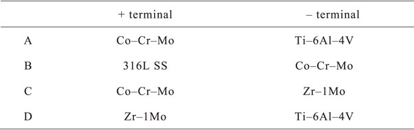
Table 2 Combinations of galvanic couplings connected to zero-shunt ammeter for galvanic current measurements.
The metal ion release induced by galvanic corrosion was measured by inductively coupled plasma–mass spectrometry (ICP-MS, ELEMENT XR, Thermo Fisher Scientific K. K., Tokyo, Japan). Test solutions were collected from the glass cells in which the galvanic current measurements were performed. The solutions were collected randomly from the glass cells after three galvanic current measurements. The amounts of the ions released from the alloys were evaluated. Fresh saline was used as the blank solution. The metal ion concentrations of the constituent elements of each alloy in saline were measured. The corresponding concentrations in the blank solution were subtracted to determine the exact concentrations following corrosion reaction.27)
3. Results and Discussions
3.1 Corrosion potential measurement
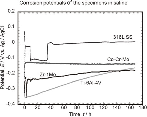
Figure 1 shows the typical behavior of the corrosion potential of each alloy during immersion in saline. The corrosion potential of Ti–6Al–4V immediately after immersion was −0.05 V, which instantaneously dropped to −0.35 V within a few seconds. Subsequently, the potential increased with the immersion time, and after 168 h, it was −0.16 V. The change in the potential after immersion is considered to be due to regeneration, i.e., growth of a mature passive film, which formed immediately after the polishing process before the measurement. The corrosion potentials of all Ti–6Al–4V specimens showed a tendency of an immediate drop after immersion, followed by a gradual increase. The corrosion potentials after 168 h varied by a maximum of approximately 60 mV, depending on the specimens. One of the major reasons for this behavior is due to the slight difference in the surface condition (e.g., chemical state of the native passive film) depending on the surface finish.
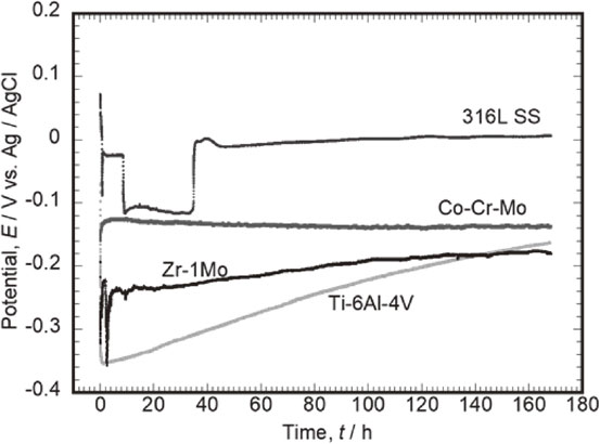
The corrosion potential of Co–Cr–Mo immediately after immersion was −0.16 V, which increased to −0.13 V in the next few minutes. Subsequently, the potential remained constant until the immersion time of 168 h was reached. The corrosion potential behaviors of Co–Cr–Mo were similar in all three measurements. Therefore, the Co–Cr–Mo passive film is stabilized immediately after immersion in saline and is considered to remain almost unchanged over a long-term immersion period.
The corrosion potential of 316L SS immediately after immersion was 0.70 V, which decreased to −0.02 V in the next few seconds. Thereafter, the potential increased slightly to 0.01 V after an immersion time of 168 h was reached. As shown in Fig. 1, one of the three corrosion potential measurements presents a significant potential drop and recovery. A potential drop phenomenon from −0.03 V to −0.12 V was observed at approximately 10 h after immersion. The potential remained at the low value for over 20 h and subsequently increased again to −0.01 V. The potential drop is considered to be due to the initiation of temporal localized corrosion on the steel surface under the effect of the chloride ions in saline, whereas the potential increase is caused by spontaneous repassivation.
The corrosion potential of Zr–1Mo immediately after immersion was −0.19 V, which decreased to −0.32 V after a few seconds. The potential subsequently increased due to altering of the passive film: thickness and/or compactness. However, as shown in Fig. 1, the potential decreases a few times (2.5 h, 9.4 h, and 133.5 h) during the testing period. This potential drop is due to the localized corrosion under the effect of the chloride ions in saline, as in the case of 316L SS. However, Zr–1Mo showed a much shorter period of potential drop than 316L SS. This suggests that the repassivation of Zr–1Mo occurs easily in saline. The corrosion potentials of all Zr–1Mo specimens after 168 h differed by approximately 160 mV depending on the specimen. This suggests that the fluctuations in the corrosion potential of Zr–1Mo are sensitive to the initial surface conditions and the occurrence of temporally localized corrosion.
3.2 Polarization test
Figure 2 shows the polarization curves of each alloy. The positive polarization of Ti–6Al–4V showed a noticeable passive region up to 2 V and no current density increase. Co–Cr–Mo also presented no pitting corrosion. A current increase due to transpassivation was observed over 0.9 V. For 316L SS, pitting corrosion, which was detected as an immediate current increase, occurred at approximately 0.41 V–0.63 V after a narrow passive region. Zr–1Mo also showed pitting corrosion approximately 0.47 V–0.67 V, similar to 316L SS.
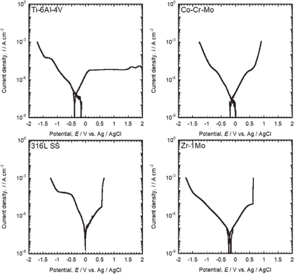
The cathodic current density increased with increasing negative applied potential for all alloys. The negative polarization of 316L SS exhibited a constant current density from approximately −0.5 V to −1.0 V. Flat regions with low sensitivity to potential changes were observed for the negative polarization of Ti–6Al–4V and 316L SS. This is considered to be a diffusion-limiting process of the reduction reaction of dissolved oxygen in saline. Subsequently, the cathodic current increased again owing to the H2 generation reaction in the further negative applied potential region.
3.3 Galvanic current measurement
3.3.1 Coupling of Co–Cr–Mo and Ti–6Al–4V
Figure 3 shows the variation in the galvanic current of the coupling of Co–Cr–Mo (connected to “+” terminal) and Ti–6Al–4V (connected to “−” terminal) over time. A negative current density of approximately 0.1 µA cm−2 was measured during the initial few seconds of coupling. Immediately afterwards the current density became approximately zero and remained at this value until 168 h. Figure 1 shows that the potential difference between Co–Cr–Mo and Ti–6Al–4V is approximately 0.1 V at 168 h after immersion in saline. In addition, the polarization curves shown in Fig. 2 suggest that neither of them experience localized corrosion in the same solution. Therefore, the coupling of Co–Cr–Mo and Ti–6Al–4V is considered to maintain a stable passive film on both alloy surfaces in saline with a negligible galvanic current. Specifically, the risk of galvanic corrosion is low even in environments where Co–Cr–Mo and Ti–6Al–4V are in contact.
3.3.2 Coupling of 316L SS and Co–Cr–Mo
Figure 4 shows the variation in the galvanic currents of the coupling of 316L SS (connected to “+” terminal) and Co–Cr–Mo (connected to “−” terminal) over time. A negative current density of approximately 2.0 µA cm−2 was measured during the initial seconds of coupling. In one of the three measurements (Fig. 4-#3), an apparent positive current density of up to 150 nA cm−2 was observed 40 h after this coupling. In this measurement, 316L SS was connected as the positive electrode and Co–Cr–Mo as the negative electrode (listed in Table 2), and the positive current is indicative of the corrosion reaction of 316L SS.
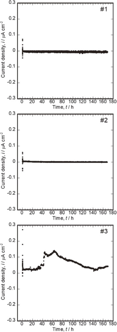
Generally, galvanic corrosion is induced on the side of an electrode that has a lower corrosion potential. In contrast, corrosion reaction on the other side of the electrode is suppressed under the negative potential shift caused by coupling. However, Fig. 1 shows that the corrosion potential of Co–Cr–Mo is approximately 0.1 V lower than that of 316L SS. The results of the galvanic current and corrosion potential measurements showed an opposite tendency. This can be attributed to the high stability of the passive film of Co–Cr–Mo and the sensitivity of 316L SS to the localized corrosion attack caused by the chloride ions in saline. Co–Cr–Mo maintained the passive film after a positive shift in the potential due to coupling. In contrast, the localized corrosion of 316L SS could not be fully inhibited even under the driving force of corrosion protection by the negative shift in the potential due to its coupling with Co–Cr–Mo. Once localized corrosion occurred on 316L SS, the corrosion potential of 316L SS became lower than that of Co–Cr–Mo. A positive current was measured as a result of the reversed positive–negative relationship. The current density gradually decreased until 140 h; however, it increased again and never recovered to zero until the end of the measurement. This suggests that once corrosion occurs in 316L SS in contact with Co–Cr–Mo, the repassivation process might be prevented and localized corrosion is prolonged. This combination of alloys has the highest risk of galvanic corrosion in this study.
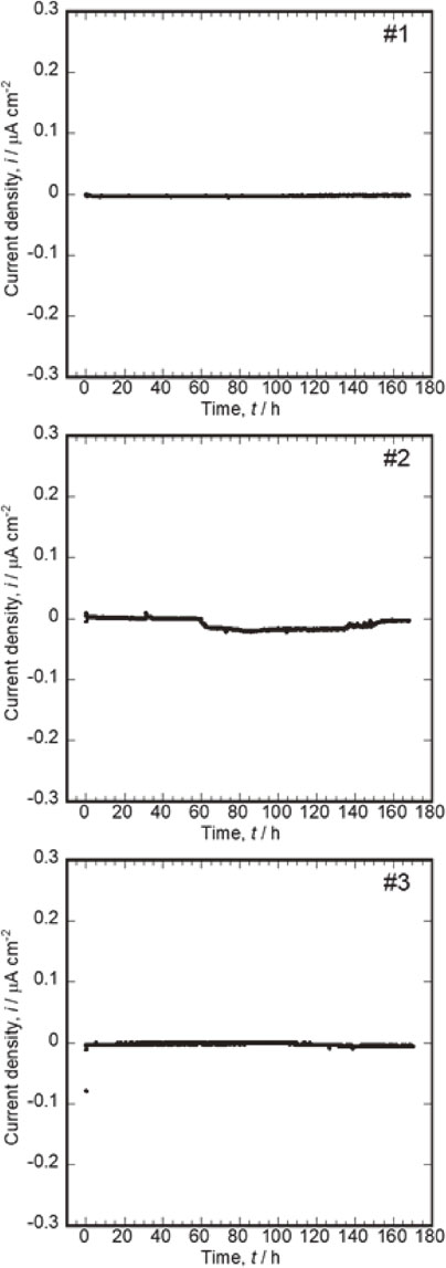
3.3.3 Coupling of Co–Cr–Mo and Zr–1Mo
The risk of galvanic corrosion when Zr–1Mo is used as a substitute for Ti–6Al–4V was evaluated. Figure 5 shows the variation in the galvanic current of the coupling of Co–Cr–Mo (connected to “+” terminal) and Zr–1Mo (connected to “−” terminal) over time. The absolute galvanic current density increased slightly in one of the three measurements (Fig. 5-#2). The negative current density increased up to 17 nA cm−2 from 60 h to 140 h after coupling, and subsequently finally recovered to zero. This is due to a temporary localized corrosion on the Zr–1Mo surface, as in 316L SS, followed by repassivation. Figure 1 shows that the corrosion potential of Zr–1Mo is lower than that of Co–Cr–Mo. However, no long-term corrosion occurred on Zr–1Mo, and little current change occurred in two of the three couplings. Furthermore, when Zr–1Mo was coupled with Co–Cr–Mo, lower current fluctuations occurred than for 316L SS (Fig. 4). Thus, Zr–1Mo possibly undergoes localized corrosion under the effect of chloride ions when in contact with Co–Cr–Mo; however, the degree of corrosion is expected to be smaller than that of 316L SS. In addition, Zr and Mo are low-toxicity elements.28) Even if small-scale localized corrosion occurs, Zr–1Mo is considered much safer than stainless steel.
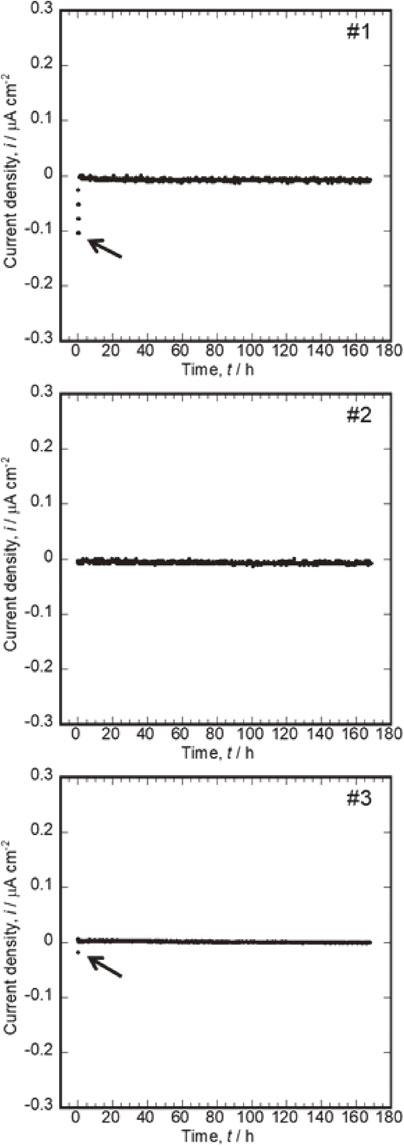
Finally, Ti and Zr alloys, which are valve metals and belong to the group 4 of elements in the periodic table, were directly compared. Figure 6 shows the variation in the galvanic current of the couplings of Zr–1Mo (connected to “+” terminal) and Ti–6Al–4V (connected to “−” terminal) over time. In one of the three measurements (Fig. 6-#3), the positive current density increased to approximately 20 nA cm−2 after 100 h and recovered to zero after 130 h. Subsequently, it increased again to approximately 30 nA cm−2 after 150 h. The positive current in this measurement indicates the occurrence of localized corrosion on the Zr–1Mo surface under the effect of the chloride ions in saline. When the positive current density decreased at 130 h, the passive film spontaneously repassivated. The reoccurrence of the galvanic corrosion at 150 h was not repassivated until the measurement ended at 168 h. However, it is expected that it would be repassivated in a relatively shorter time because of the lower sensitivity of Zr–1Mo to localized corrosion than that of stainless steel. In addition, Zr–1Mo and Ti–6Al–4V showed similar corrosion potential tendencies, as presented in Fig. 1. Therefore, the similar corrosion potential difference may be another factor causing the relatively smaller degree of galvanic corrosion of the Zr–1Mo and Ti–6Al–4V couple.
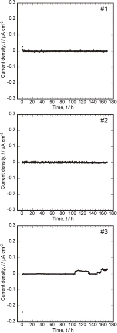
Table 3 lists the amounts of the ions of each element released after coupling. Al ions were detected in concentrations of 0.24 µg L−1 and 0.21 µg L−1 in the solutions after the coupling of Ti–6Al–4V and Co–Cr–Mo and of Ti–6Al–4V and Zr–1Mo, respectively. Figures 3 and 6 show that these couplings exhibit higher current density values in the seconds immediately after coupling, which suggests that some of the Al in Ti–6Al–4V is released at this moment. Ni ions in concentration of 0.28 µg L−1 was also detected in the coupling of 316L SS and Co–Cr–Mo. This is attributed to the localized corrosion of 316L SS. Fe ions, the main components of 316L SS, were also detected at higher concentrations in the test solution. However, the calculated concentration listed in Table 3 is under the detection limit because the same concentration level of Fe ions is detected even in the blank solution of fresh saline. We suspect that this is caused by contamination from the equipment used for preparing the solution or the memory effect. The latter is a measurement disturbance phenomenon specific to ICP–MS that occurs when uncommon concentrations of solutions are used. Therefore, it is necessary to state as a limitation that the results of these metal ion release evaluations in this study must be verified to be accurate by most precise remeasurements, considering sensitive interfering factors such as contamination, impurities in the reagents and pure water, and measurement procedure. However, the galvanic coupling measurements performed in this study revealed that the metal ion release was only in concentrations of the order of parts per trillion, which is almost the threshold of the detection limit of ICP–MS measurements. Therefore, the side effects of the metal ions released from implants due to galvanic corrosion could be considered to be significantly small or negligible if the alloys are composed of less allergenic elements.
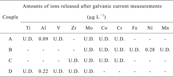
Table 3 Concentrations of metal ions released during 168 h of galvanic coupling. (U.D.: Under detection limit, -: No measurement)
4. Conclusion
Galvanic corrosion in couples of Ti–6Al–4V, Co–Cr–Mo, 316L SS, and Zr–1Mo for orthopedic implants was evaluated. Ti–6Al–4V and Co–Cr–Mo did not exhibit localized corrosion in saline and maintained highly stable passive films. In uses involving contact between Ti–6Al–4V and Co–Cr–Mo, the risk of galvanic corrosion was determined to be negligible. The couplings with 316L SS or Zr–1Mo showed metastable localized corrosion under the effect of the chloride ions in saline; however, the passive film, temporally broken by localized corrosion occurrence, spontaneously repassivated with immersion time. The degree of localized corrosion of the Zr–1Mo surface was less than that of 316L SS. Although the Ti alloys showed excellent results even under galvanic conditions with exceptional biosafety, Zr–1Mo having sufficient galvanic corrosion resistance can also be considered to substitute 316L SS.
Acknowledgments
This study was supported by JSPS KAKENHI (grant numbers 17K06835, 25709064, and 19H04464). In addition, a part of this study was supported by the Research Center for Biomedical Engineering.
REFERENCES
- 1) D.M. Brunette, P. Tengvall, M. Textor and P. Thomsen: Titanium in Medicine: Material Science, Surface Science, Engineering, Biological Responses and Medical Applications, (Springer, Berlin, 2001).
- 2) Y. Nakayama, T. Yamamuro, Y. Kotoura and M. Oka: Biomaterials 10 (1989) 420–424. doi:10.1016/0142-9612(89)90134-8
- 3) V.A. Alves, R.Q. Reis, I.C.B. Santos, D.G. Souza, T.D. Goncalves, M.A. Pereira-da-Silva, A. Rossi and L.A. da Silva: Corros. Sci. 51 (2009) 2473–2482. doi:10.1016/j.corsci.2009.06.035
- 4) R.I.M. Asri, W.S.W. Harun, M. Samykano, N.A.C. Lah, S.A.C. Ghani, F. Tarlochan and M.R. Raza: Mater. Sci. Eng. C 77 (2017) 1261–1274. doi:10.1016/j.msec.2017.04.102
- 5) N.S. Manam, W.S.W. Harun, D.N.A. Shri, S.A.C. Ghani, T. Kurniawan, M.H. Ismail and M.H.I. Ibrahim: J. Alloy. Compd. 701 (2017) 698–715. doi:10.1016/j.jallcom.2017.01.196
- 6) N. Eliaz: Materials 12 (2019) 407. doi:10.3390/ma12030407
- 7) T. Hanawa: Front. Bioeng. Biotechnol. 7 (2019) 170. doi:10.3389/fbioe.2019.00170
- 8) R. Brånemark, L.O. Öhrnell, R. Skalak, L. Carlsson and P.I. Brånemark: J. Orthop. Res. 16 (1998) 61–69. doi:10.1002/jor.1100160111
- 9) P.L. Sanderson, W. Ryan and P.G. Turner: Injury Int. J. Care Injured 23 (1992) 29–30. doi:10.1016/0020-1383(92)90121-8
- 10) M. Geetha, A.K. Singh, R. Asokamani and A.K. Gogia: Prog. Mater. Sci. 54 (2009) 397–425. doi:10.1016/j.pmatsci.2008.06.004
- 11) S. Bauer, P. Schmuki, K. von der Mark and J. Park: Prog. Mater. Sci. 58 (2013) 261–326. doi:10.1016/j.pmatsci.2012.09.001
- 12) M. Kaur and K. Singh: Mater. Sci. Eng. C 102 (2019) 844–862. doi:10.1016/j.msec.2019.04.064
- 13) S.D. Lim, Y. Takada, K.H. Kim and O. Okuno: Dent. Mater. J. 22 (2003) 96–110. doi:10.4012/dmj.22.96
- 14) Y. Takada, S.D. Lim, K. Asami, K.H. Kim and O. Okuno: Mater. Trans. 43 (2002) 3146–3154. doi:10.2320/matertrans.43.3146
- 15) N. Takahashi, Y. Takada and O. Okuno: Dent. Mater. J. 27 (2008) 237–242. doi:10.4012/dmj.27.237
- 16) A. Bakhtari, T.G. Bradley, W.K. Lobb and D.W. Berzins: Am. J. Orthod. Dentofac. Orthop. 140 (2011) 25–31. doi:10.1016/j.ajodo.2010.05.021
- 17) Suyalatu, R. Kondo, Y. Tsutsumi, H. Doi, N. Nomura and T. Hanawa: Acta Biomater. 7 (2011) 4259–4266. doi:10.1016/j.actbio.2011.07.005
- 18) Suyalatu, N. Nomura, K. Oya, Y. Tanaka, R. Kondo, H. Doi, Y. Tsutsumi and T. Hanawa: Acta Biomater. 6 (2010) 1033–1038. doi:10.1016/j.actbio.2009.09.013
- 19) M. Ashida, T. Sugimoto, N. Nomura, Y. Tsutsumi, P. Chen, H. Doi and T. Hanawa: Mater. Trans. 56 (2015) 1544–1548. doi:10.2320/matertrans.M2015098
- 20) M. Ashida, M. Morita, Y. Tsutsumi, N. Nomura, H. Doi, P. Chen and T. Hanawa: Metals 8 (2018) 454. doi:10.3390/met8060454
- 21) Y. Tsutsumi, I. Muto, S. Nakano, J. Tsukada, T. Manaka, P. Chen, M. Ashida, Y. Sugawara, M. Shimojo, N. Hara, H. Katayama and T. Hanawa: J. Electrochem. Soc. 167 (2020) 141507. doi:10.1149/1945-7111/abc5d8
- 22) T. Manaka, Y. Tsutsumi, P. Chen, M. Ashida, H. Katayama and T. Hanawa: J. Electrochem. Soc. 168 (2021) 121505. doi:10.1149/1945-7111/ac3ff1
- 23) S. Hornkjøl: Electrochim. Acta 33 (1988) 289–292. doi:10.1016/0013-4686(88)80016-1
- 24) D.R. Knittel and A. Bronson: Corrosion 40 (1984) 9–14. doi:10.5006/1.3579296
- 25) G.C. Palit and H.S. Gadiyar: Corrosion 43 (1987) 140–148. doi:10.5006/1.3583126
- 26) Y. Tanaka, E. Kobayashi, S. Hiromoto, K. Asami, H. Imai and T. Hanawa: J. Mater. Sci. Mater. Med. 18 (2007) 797–806. doi:10.1007/s10856-006-0004-2
- 27) Y. Tsutsumi, S. Bartakova, P. Prachar, Suyalatu, S. Migita, H. Doi, N. Nomura and T. Hanawa: J. Electrochem. Soc. 159 (2012) C435–C440. doi:10.1149/2.045210jes
- 28) A. Yamamoto, R. Honma and M. Sumita: J. Biomed. Mater. Res. 39 (1998) 331–340. doi:10.1002/(SICI)1097-4636(199802)39:2%3C331::AID-JBM22%3E3.0.CO%3B2-E