Abstract
To prevent infection in dental implants using photocatalytic activity under visible-light irradiation, the fabrication of Au-added TiO2 layers on Ti substrates and their antibacterial properties were studied. Pure Au and Ti–(60, 40) mol%Au alloy films with thicknesses of 10–47 nm were sputtered onto Ti, followed by thermal oxidation in air at 873 K for 1.8 ks to form TiO2 layers. The antibacterial properties against Escherichia coli, cytotoxicity, and bonding strength to Ti substrates were evaluated. The highest antibacterial activity under visible-light irradiation was obtained when the sputtered film was pure Au and its thickness was 38 nm. Compared with as-polished commercially pure Ti, the number of viable mouse osteoblast-like cells and human gingival fibroblasts on Au-added TiO2 layers increased after placement in the dark but decreased after visible-light irradiation. The best antibacterial property-bonding strength balance was achieved when the Ti–40 mol%Au sputtered film with a thickness of 42 nm was formed on Ti. To the best of our knowledge, this study is the first to report the formation of TiO2 layers with antibacterial activity under visible-light irradiation by combining Au-sputtering and thermal oxidation of Ti.
1. Introduction
While dental implants have an excellent function in recovering mastication ability and aesthetic appearance, they also carry a risk of infection.1,2) Implant bodies are usually made of Ti or Ti alloys, which provide long and strong fixation with the bone due to osseointegration.3–5) In many cases, implant surfaces are roughened to achieve rapid and strong osseointegration. However, surface roughening increases the risk of bacterial attachment and growth.6) Therefore, surface modification processes with antibacterial properties and improved bone compatibility are needed.7)
Grischke et al. reviewed studies on the antibacterial surfaces of implants.8) Such antibacterial surfaces may negatively affect human cells. Therefore, control of the bactericidal effect is essential. Compared to other antibacterial surfaces, such as coatings of carriers of antimicrobial agents9–11) and elements12–16) and a peptide,17) TiO2 coatings18–24) offer better controllability because their bactericidal effect is only active while exposed to light. Additionally, photocatalytic decomposition of hydrocarbon contaminations and photoinduced hydrophilic reactions improve cell attachment and calcification.25–27) Therefore, photocatalytic TiO2 coatings can achieve both controllable antibacterial properties and high bone compatibility.
Previously, Au-added TiO2 layers formed by the thermal oxidation of Ti–(4–10) mol%Au alloys were reported to show photoinduced organic decomposition28) and antibacterial properties20) under visible-light irradiation. These Au-added TiO2 layers killed more than 90% of Escherichia coli (E. coli) under 14.4 ks of visible-light irradiation at an intensity of 1 mW·cm−2.20) However, this process cannot be applied to dental implant bodies directly because commercially available Ti dental implants usually do not contain Au.
In this study, we hypothesized that visible-light-photocatalytically active TiO2 layers could be formed by Au sputtering and thermal oxidation, even on commercially pure (CP) Ti substrates, and show antibacterial properties under visible-light irradiation. Three types of Au sputtered films with different Au concentrations, including a pure Au film, were prepared on the CP Ti substrates. The film thickness was controlled by varying the sputtering time. After Au sputtering, the Ti substrates with Au sputtered films were oxidized in air. The phases, surface and cross-sectional structures, and Au concentrations of the TiO2 layers were studied. The antibacterial properties and cytotoxicity under visible-light irradiation and bonding strength of the Au-added TiO2 layers were evaluated.
2. Materials and Methods
2.1 Formation of Au-added TiO2 layer
Mirror polished plates of CP Ti (Japanese industrial standards (JIS) Gr. 2, ϕ12 mm × 1t mm) were used as substrates after sonication in ethanol and ultrapure water. Three types of targets were used for Au sputtering: Au disk (99.99%, Vacuum Device) and Ti disks (99.9%, ϕ50.8 mm × 3t mm) mounted with eight and four Au pellets (99.95%, 5w mm × 5l mm × 0.7t mm). The Au disk was placed in a direct-current magnetron sputtering instrument (MSP-10, Vacuum Device). After evacuation to 2 Pa, sputtering was conducted for 30, 60, and 120 s at a chamber pressure of 7 Pa and a target current of 35 mA. The Ti disk mounted with Au pellets was placed in a radio frequency (RF) magnetron sputtering instrument (SP-3003-SS, Toei Scientific Industrial). After evacuation to 1.0 × 10⁻³ Pa, sputtering was conducted for 600 and 1500 s in an Ar gas (>99.9999%) flow with a flow rate of 5 sccm at a chamber pressure of 5 Pa and an RF power of 50 W. The Au concentrations in the sputtered films were 56 and 42 mol% for eight and four Au pellets, respectively, as measured using X-ray photoelectron spectrometry (XPS, KRATOS AXIS-Ultra DLD, Shimadzu). The sputtered film thickness was measured using a profilometer (dektak3, ULVAC). Hereafter, each specimen is referred to as Au(x, Lfilm), where x is the Au concentration in the sputtered film and Lfilm is the Au–Ti sputtered film thickness. For the pure Au sputtered film, x was set to 100 mol%. For the films sputtered by Ti disks with eight and four Au pellets, x was set to 60 and 40 mol%, respectively. The abbreviations and sputtering conditions used for each specimen are listed in Table 1.
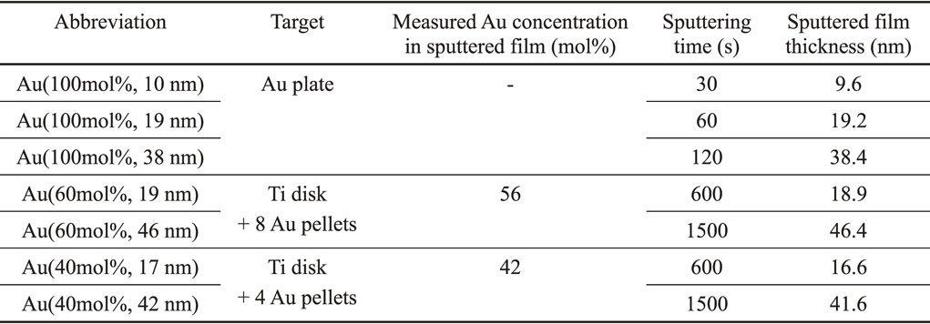
Table 1 Abbreviations and sputtering conditions used for each specimen.
Following sputtering, the specimens were subjected to thermal oxidation. The heating rate was 1.4 × 10⁻¹ K·s−1. The specimens were held in air at 873 K for 1.8 ks and cooled in a furnace to room temperature.20)
2.2 Characterization of the TiO2 layer
After thermal oxidation, the phases of the surface reaction layers were identified using thin-film X-ray diffraction (α–2θ XRD, SmartLab, Rigaku) and θ–2θ XRD (ULTIMA IV-HTXA, Rigaku). Cu Kα radiation was used in this study. The incident angle was set at 0.5° for α–2θ XRD. The surfaces and cross sections of the TiO2 layers and TiO2-layer-peeled region were observed in the backscattered electron (BSE) mode and analyzed through energy-dispersive X-ray spectroscopy (EDX) and scanning electron microscopy (SEM, XL30FEG, Philips). The chemical states and elemental concentrations at the surface of the TiO2 layer were measured by XPS. The binding energy was calibrated to the C 1s peak of C–C and C–H (284.8 eV).29) For the XPS depth analysis, the surface of the specimen was etched by Ar sputtering.
2.3 Evaluation of antibacterial properties
The antibacterial properties of the TiO2 layer under visible light against E. coli (DH5α) were evaluated using the glass adhesion method.20,23,30,31) We selected the DH5α strain as E. coli as it is a special strain used for DNA transformation because its genotype has been analyzed and it is relatively safe to use in the laboratory.12) The DH5α strain that was not in a competent state was used; its membrane components, state, and structure are equivalent to those of wild-type E. coli and its genome is almost the same as that of wild-type E. coli, although its cell membrane structure is slightly different from that of wild-type E. coli. Therefore, the use of DH5α possesses universality with respect to antibacterial susceptibility assessment against E. coli. Bacterial suspensions with a bacterial concentration of 108 CFU·mL−1 were prepared using a nutrient broth (NB, MERCK KGaA) medium. Three identical TiO2 layers were prepared for each sputtering condition. The TiO2 layers were sonicated in ethanol and ultrapure water and subjected to high-pressure steam sterilization. A 5 µL drop of the bacterial suspension was placed on the TiO2 layer and covered with a glass slide (ϕ10 mm × 0.12–0.15t mm, Matsunami Glass). The bacteria on each TiO2 layer were collected in 2 mL of phosphate buffered saline (PBS) after the following three treatments: no treatment (immediately after placing the glass slide), visible-light irradiation, and placement in the dark. A Xe lamp (XEF-152S, Kenko Tokina) mounted with a cutoff filter (SC-40, FUJIFILM) was used as the visible-light source (λ ≥ 400 nm). Based on the JIS,30) an irradiating intensity (I) of 1 mW·cm−2 was used for an irradiation time (tvis) of 14.4 ks. The treatments were conducted with a specimen placed in each well of a 12-well microplate (Falcon 353043, Corning Inc.), and the wells were covered with a lid. To avoid being affected by drying, the following two measures were taken during the test: (1) a sterilized filter paper was laid in each well and wetted with sterilized water to maintain the humidity in the well. To ensure separation between each specimen and the wetted filter paper, SiO2 glass pellets were placed on the wetted filter paper and, thereafter, the specimen was placed horizontally on these pellets.30) (2) 1 mL of sterilized water was put in each empty well not used for testing. From each suspension, the number of viable bacteria at initial (N0), after visible-light irradiation (Nvis), and after placement in the dark (Ndark) was obtained by the diluted plate method using PBS. Dilution factors (E) of 1, 10, and 100 were used. After 100 µL of the bacterial suspension was smeared onto two NB agar plates and incubated for 20 h, the number of colonies (Z) was counted using the agar plates with 30–300 colonies.30) The number of viable bacteria was calculated as follows:
| \begin{equation}
N = Z \times E \times 2/0.1
\end{equation}
| (1) |
where 2 and 0.1 refer to the volumes (mL) of PBS used to collect the bacteria and the suspension smeared onto the agar plates, respectively. If the number of colonies was less than 30 at
E = 1,
N was set to
Z. The logarithms of the normalized number of viable bacteria after visible-light irradiation (log(
Nvis/
N0)) and placement in the dark (log(
Ndark/
N0)) were calculated. Tests were conducted at
n = 3.
2.4 Evaluation of cytotoxicity
To study the compatibility with bone and gingival tissues, the number of viable cells on the TiO2 layers after placement in the dark and under visible-light irradiation was evaluated using alamarBlue.22,32) Mouse osteoblast-like cell line (MC3T3-E1) and human gingival fibroblasts (hGF-1) were used as test cells. These cells were precultured in Dulbecco’s modified Eagle’s medium (DMEM, FUJIFILM Wako Pure Chemical)–fetal bovine serum (20%, Gibco qualified FBS, Thermo Fisher Scientific) containing penicillin (penicillin G potassium, Meiji Seika Pharma) and streptomycin (streptomycin sulfate MEIJI, Meiji Seika Pharma).33) High- and low-glucose DMEM were used for MC3T3-E1 and hGF-1, respectively.
This test consists of four steps: (1) formation of a cell monolayer as a standardized initial state, (2) treatment of the cell monolayer by visible-light irradiation or placement in the dark, (3) cultivation of the cells using alamarBlue, and (4) measurement of the number of viable cells. If the cells were damaged or killed during step (2) and the number of viable cells decreased, then the number of viable cells obtained after step (3) decreased. In this procedure, therefore, the cytotoxicity during the treatment in step (2) can be determined from the number of viable cells after step (3).
As-polished CP Ti and the TiO2 layers were used as specimens. After sonication in ethanol and ultrapure water and high-pressure steam sterilization, each specimen was placed in a well of a 24-well plate (Falcon, Corning). Each well was seeded with 5 × 10⁴ testing cells in 500 µL of the medium, and a cell monolayer was formed by culturing the wells for 24 h (step (1)). For comparison, wells with neither specimens nor cells, but only the medium, were also prepared and named “Blank”. The 24-well plate was placed on a 310-K plate warmer (HIENAI Plate Warmer GX01, Cosmo Bio) and subjected to visible-light irradiation or placed in the dark (step (2)). The light source and filter were the same as those used in the antibacterial property tests. Because the cells could not survive for a long time outside the incubator, the irradiating condition was set at I = 15 mW·cm−2 and tvis = 1.8 ks.
Following treatment with visible light or placement in the dark, 50 µL of alamarBlue cell viability reagent (Invitrogen DAL1025, Thermo Fisher Scientific) was added to each well, and the wells were cultured for 24 h (step (3)). After culturing, 100 µL of the medium was collected, and its absorbance at 560 nm (A560 nm) was measured using a microplate reader (GloMax-Multi Detection System, Promega) with 600 nm (A600 nm) as the reference wavelength (step (4)). A560 nm − A600 nm reflects the number of viable cells. Tests were conducted at n = 4.
2.5 Evaluation of bonding strength
The bonding strengths of the TiO2 layers were measured by performing stud-pull tests using a mechanical strength tester (Romulus, Quad; ϕ2.7 mm, n = 5). Studs with epoxy glue (ϕ2.7 mm, P/N901106, Quad Group Inc.) were fixed onto the surfaces of the TiO2 layers and then pulled out at a loading speed of 1.0 kgf·s−1.
2.6 Statistical processing
For antibacterial properties, a Student’s t-test was performed between log(Nvis/N0) and log(Ndark/N0) for each TiO2 layer at n = 3. For the number of viable cells, the Tukey-Kramer multiple comparison test was performed on A560 nm − A600 nm at n = 4. The significance level was set at p = 0.05 and 0.01.
3. Results
3.1 TiO2 layers formed on Ti with Au–Ti sputtered films
Figure 1 shows the α–2θ XRD patterns of the specimens after sputtering and thermal oxidation. For comparison, the α–2θ XRD pattern of the TiO2 layer formed on CP Ti without Au sputtering is also shown. Rutile was detected in the TiO2 layer of each specimen. According to the α–2θ XRD patterns, metallic Au was detected on the surface of the TiO2 layers of Au(100 mol%, 10–38 nm), Au(60 mol%, (19, 46) nm), and Au(40 mol%, 17 nm).
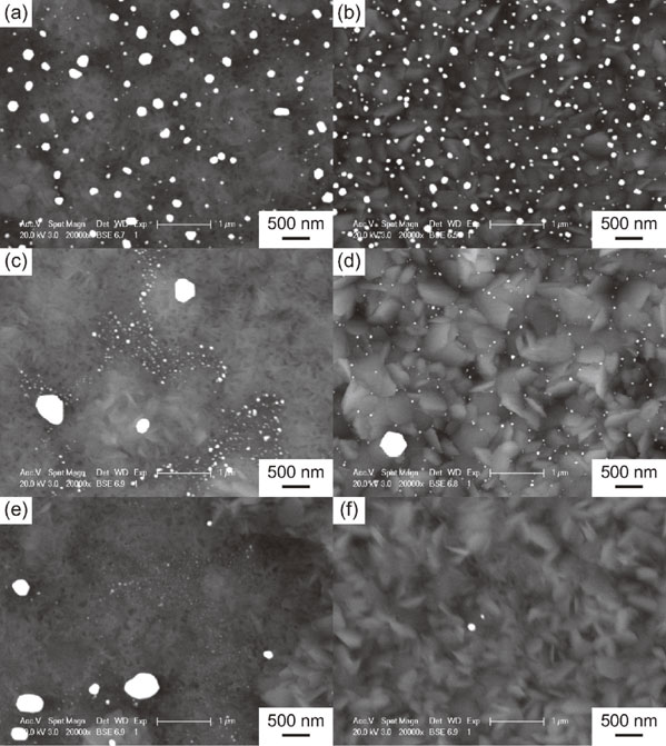
Figure 2 shows the SEM-BSE images of the surfaces of the TiO2 layers formed on Au(100 mol%, (10, 38) nm), Au(60 mol%, (19, 46) nm), and Au(40 mol%, (17, 42) nm). Bright particles are observed for each TiO2 layer, corresponding to metallic Au particles.
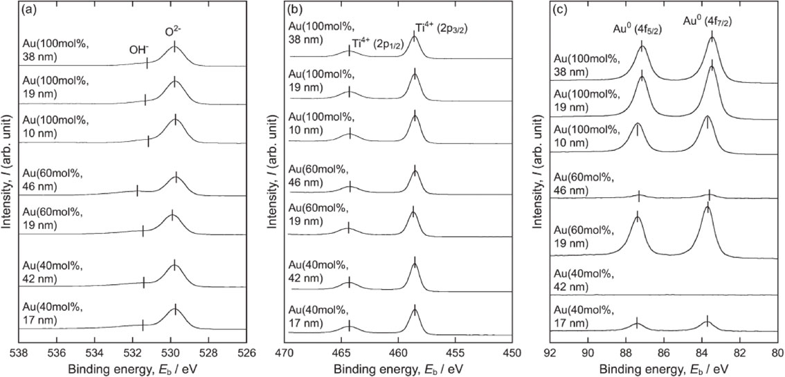
The XPS peaks assigned to O2− and Ti4+ were detected in the spectra shown in Figs. 3(a) and (b), respectively. The binding energy of O 1s for O2− was 529.7–529.9 eV and that of Ti 2p3/2 for Ti4+ was 458.5–458.7 eV. These values are almost equivalent to the values reported for TiO2.34,35) Surface-adhered OH− 34) was also detected in the O 1s spectra. Except in the case of Au(40 mol%, 42 nm), Au peaks (Au 4f7/2 at 83.4–83.7 eV) were detected (Fig. 3(c)). According to Wang et al.36) and Liu et al.,37) metallic Au nanoparticles adhering to TiO2 results in Au 4f7/2 peaks at 83.2–83.6 eV, which were negatively shifted from those of bulk metallic Au (84.0 eV) owing to electron transfer from TiO2 to Au nanoparticles. Based on these reports, the Au peaks detected from the TiO2 layers in this study were attributed to metallic Au. These results aligned with those of α–2θ XRD patterns (Fig. 2).
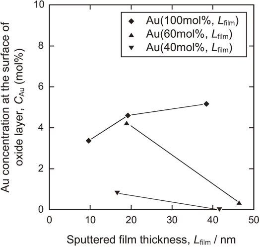
The Au concentration at the outermost surface of the TiO2 layers, as calculated from the XPS spectra of O 1s, Ti 2p, and Au 4f (Fig. 3), is depicted in Fig. 4 as a function of Lfilm. When the sputtered film thickness was the same, the Au concentration at the surface of the oxide layer increases as the Au concentration in the sputtered film increased. For both Au(60 mol%, Lfilm) and Au(40 mol%, Lfilm), Au concentrations decrease as Lfilm increases. In contrast, for Au(100 mol%, Lfilm), the Au concentration increases when the sputtered film thickness increases.
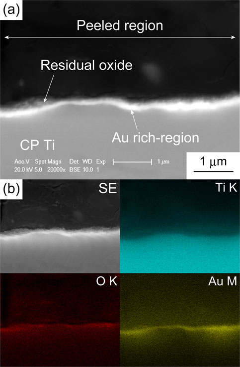
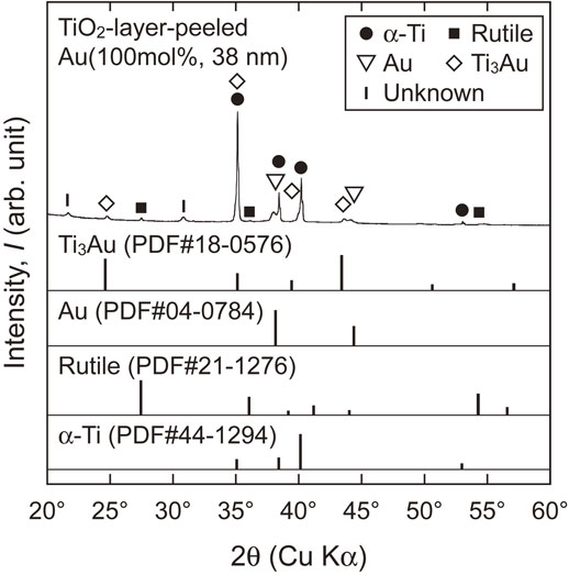
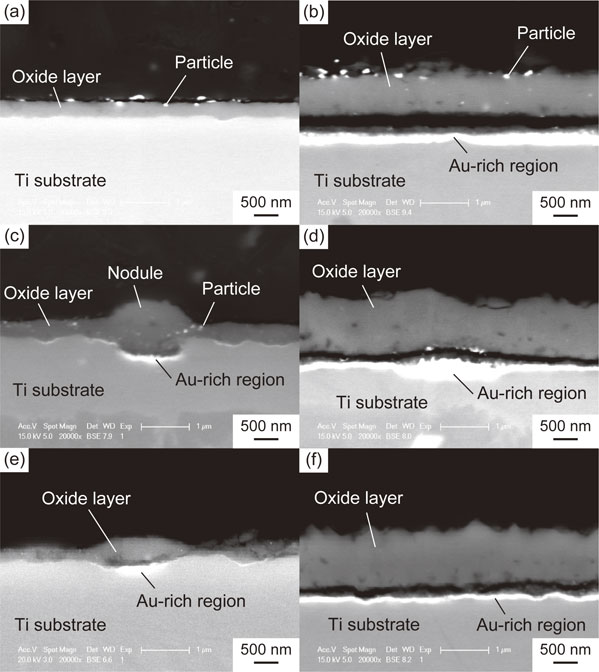
Cross sections of the TiO2 layers of Au(100 mol%, (10, 38) nm), Au(60 mol%, (19, 46) nm), and Au(40 mol%, (17, 42) nm) are shown in Fig. 5. For the specimens with relatively thick sputtered films, i.e., Au(100 mol%, 38 nm), Au(60 mol%, 46 nm), and Au(40 mol%, 42 nm), continuous bright regions formed at the TiO2 layer/substrate interface. As presented in the images in Fig. 6, which were captured after the stud-pull test, the EDX analysis revealed that these bright regions are enriched in Au; they are, therefore, referred to as Au-rich regions hereafter. From the θ–2θ XRD analysis of the TiO2-layer-peeled Au(100 mol%, 38 nm) after the stud-pull test, Ti3Au was detected in addition to α-Ti of the substrate (Fig. 7). The presence of Ti3Au was also confirmed by the XPS depth analysis. Figure 8(a) presents the depth profile of the atomic concentration of O, Ti, and Au for the TiO2 layer of Au(100 mol%, 38 nm), indicating the formation of the Au-rich region beneath the TiO2 layer at the depth of 800–1000 nm. Figure 8(b) presents the Au 4f XPS spectra at the surface and at the Au-rich region. The binding energies for both the spectra were not calibrated because the surfaces C–C and C–H were eliminated by Ar sputtering during depth analysis. Compared with the metallic Au peaks in the Au 4f XPS spectrum at the surface of the TiO2 layer (depth = 0 nm), the peaks at the Au-rich region (depth = 850 nm) had a higher binding energy by 0.8 eV. It was reported that the binding energy of Ti3Au was 0.76 eV higher than that of bulk Au.38) Therefore, it can be concluded that Ti3Au was formed at the interface between the TiO2 layer and the substrate. For Au(60 mol%, 19 nm) and Au(40 mol%, 17 nm), discontinuous Au-rich regions formed (Figs. 5(c) and (e)). The Au-rich region was not formed by the thermal oxidation of Au(100 mol%, 10 nm) (Fig. 5(a)). For Au(60 mol%, 19 nm), oxide nodules are observed above the localized Au-rich regions (Fig. 5(c)). Thus, the Au-rich regions became more noticeable as the thickness and Au concentration of the sputtered film increased.
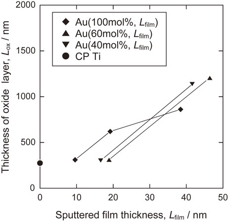
The thickness of the TiO2 layer after thermal oxidation is shown in Fig. 9 as a function of Lfilm. The thickness of the oxide layer increases with the thickness of the sputtered film.
3.2 Antibacterial properties and cytotoxicity
Figure 10 shows the logarithms of the normalized numbers of viable bacteria on the TiO2 layers. In this evaluation, log(Nvis/N0) decreased significantly compared with log(Ndark/N0) for Au(100 mol%, (19, 38) nm), Au(60 mol%, 46 nm), and Au(40 mol%, (17, 42) nm). This demonstrates that these TiO2 layers exhibit antibacterial properties under visible-light irradiation. Log(Nvis/N0) decrease as the sputtered film thickness increased for each Au concentration in the sputtered film. Among the specimens, the TiO2 layer formed on Au(100 mol%, 38 nm) showed the lowest log(Nvis/N0) and the greatest decrease compared with log(Ndark/N0).
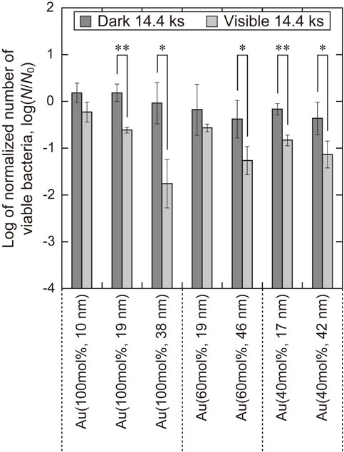
Figure 11(a) shows A560 nm − A600 nm of MC3T3-E1 on the as-polished CP Ti and the TiO2 layers for Au(100 mol%, (19, 38) nm), which exhibited the excellent antibacterial activity under visible-light irradiation. The number of viable cells of MC3T3-E1 on the as-polished CP Ti did not decrease following visible-light irradiation compared to that after placement in the dark. This result indicates that visible-light irradiation itself did not affect the number of viable cells. The number of viable cells on each TiO2 layer after visible-light irradiation was significantly lower than that on as-polished CP Ti; therefore, the TiO2 layers exhibited cytotoxicity under visible-light irradiation. In contrast, the number of viable cells on each TiO2 layer after placement in the dark was significantly higher than that on as-polished CP Ti. This indicates that the TiO2 layers were not cytotoxic in the dark. Figure 11(b) shows A560 nm − A600 nm of hGF-1 on each specimen after visible-light irradiation and placement in the dark. Similar to the results of MC3T3-E1, the TiO2 layers exhibited cytotoxicity under visible-light irradiation but not in the dark.
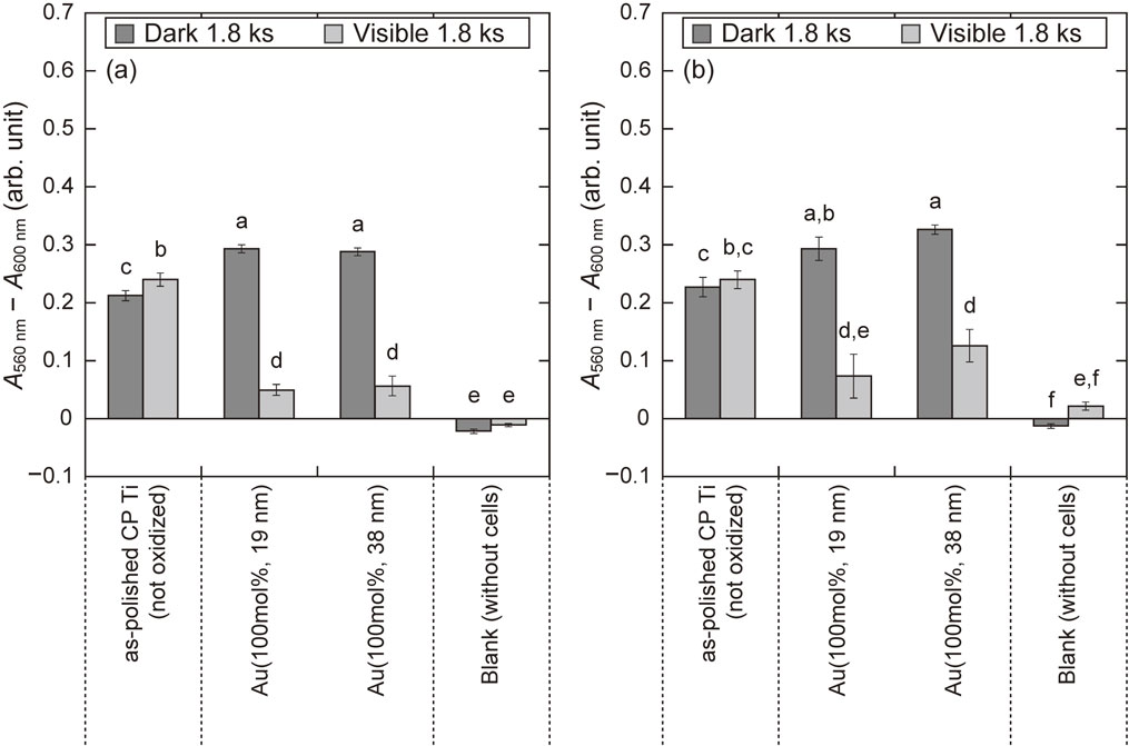
Figure 12(a) shows the relationship between the sputtered film thickness and bonding strength. For CP Ti, Au(100 mol%, 10 nm), and Au(40 mol%, 17 nm), the adhesives were fractured while the TiO2 layers were not fractured. Therefore, the actual bonding strength of these TiO2 layers is greater than the measured value of around 70 MPa. As the sputtered film thickness increased, the TiO2 layer peeled and the bonding strength decreased. For Au(100 mol%, (10, 19) nm) and Au(40 mol%, (17, 42) nm), the TiO2 layers exhibited bonding strengths greater than 15 MPa, which is required for implant coatings.39) In contrast, for Au(100 mol%, 38 nm) and Au(60 mol%, (19, 46) nm), the bonding strength was below 15 MPa. The cross-section of Au(100 mol%, 38 nm) after the stud-pull test was examined by SEM-BSE (Fig. 12(b)), confirming that a fracture occurred at the TiO2 layer/Au-rich region interface.
4. Discussion
4.1 TiO2 formation combining Au–Ti film sputtering and thermal oxidation
An increase in the Au–Ti sputtered film thickness promoted the oxidation of Ti with the sputtered films (Figs. 5 and 9). Previously, Ueda et al.20) studied the oxidation of Ti–Au alloy at 873 K and reported that oxidation was promoted as the Au concentration in the alloy increased up to 5 mol%. It was proposed that more oxygen vacancies were formed as more Au3+ ions dissolved into Ti sites in the TiO2 lattice, thereby promoting the oxidation of the Ti–Au alloy. The promoted oxidation of Ti with Au–Ti sputtered films is thought to occur via the same mechanism as that of the Ti–Au alloy. Accordingly, Au3+ ions were thought to be dissolved into the TiO2 layers.
Li and Li40) and Esfandfard et al.41) reported that cationic Au (Au3+) could improve the visible-light activity of TiO2 photocatalysts by forming a mid-gap state. The results of the present study are consistent with these reports. The TiO2 layers formed by the thermal oxidation of Ti with Au–Ti sputtered films showed greater antibacterial properties upon visible-light irradiation for greater sputtered film thicknesses (Fig. 10), in which the content of Au introduced to the TiO2 layer was higher. Although the mechanism of visible-light activation of the Au-added TiO2 layer formed by thermal oxidation is not fully understood, the dissolution of Au3+ ions could be one of the contributing factors.
According to Wang et al.36) and Liu et al.,37) a negative shift in the binding energy of metallic Au in Au/TiO2 implies the good electrical connection between Au nanoparticles and TiO2, which enables the interfacial transfers of the electron and hole to the electrolyte through Au nanoparticles. Further, Liu et al.37) reported that the enhancement of such interfacial transfers improves the property of photocatalytic degradation of methyl orange under both UV and visible-light irradiation. In this study, the largest negative shift (83.4 eV) of binding energy of metallic Au was obtained for Au(100 mol%, 38 nm), which exhibited the strongest antibacterial property under visible-light irradiation. This indicates that the Au-added TiO2 layer formed on Au(100 mol%, 38 nm) produced a better electrical connection compared with other specimens. Thus, the excellent antibacterial property of the Au-added TiO2 layer for Au(100 mol%, 38 nm) under visible-light irradiation could be possibly attributed to the good electrical connection between the Au particles and TiO2 layer as well as visible-light activation by the dissolved Au3+.
4.2 Comparison of antibacterial properties
To compare the antibacterial properties, we calculated the value of antibacterial property, R, of TiO2 layers as follows:20–23,31)
| \begin{equation}
R = -{\log}(N_{\text{vis}}/N_{0})
\end{equation}
| (2) |
Using the glass adhesion method, Sadowski
et al.31) and Ueda
et al.20,23) evaluated the antibacterial properties of TiO
2 layers. Sadowski
et al.31) reported that TiO
2 layers impregnated with the photosensitizer, catechol, deactivated 93% of
E. coli (initially 10
5 CFU·mL
−1 in 100 µL) under visible light (λ
max = 405 nm,
I = 1 mW·cm
−2, and
tvis = 14.4 ks), yielding
R = 1.1. Ueda
et al. showed that an Au-added TiO
2 layer formed on Ti–5 mol%Au alloy showed
R = 1.8,
20) and a carbon-dissolved anatase-containing TiO
2 layer, which was formed using two-step thermal oxidation,
42,43) showed
R ≈ 2.0 against
E. coli (10
8 CFU·mL
−1 in 5 µL) under visible-light irradiation (λ ≥ 400 nm,
I = 1 mW·cm
−2, and
tvis = 14.4 ks).
23) The evaluating method and irradiation conditions in these studies were similar to those used in this study. Herein, the TiO
2 layer formed on Au(100 mol%, 38 nm) showed the best antibacterial properties against
E. coli (10
8 CFU·mL
−1 in 5 µL) under visible-light irradiation, yielding
R = 1.8 (
Fig. 10). From the comparison of
R values, it was revealed that the thermal oxidation of Ti with Au–Ti sputtered films can fabricate Au-added TiO
2 layers with antibacterial properties comparable to those of the thermal oxidation of Ti–Au alloys.
20)
When dental implants are infected, gingival and bone tissues around the implants recede owing to inflammation. In such cases, it will be possible to irradiate visible light onto the exposed surfaces of the implants using a pointed light source such as a fiber tip. As shown in Figs. 10 and 11, the Au-added TiO2 layers exhibited antibacterial properties under visible-light irradiation and no cytotoxicity against MC3T3-E1 and hGF-1 in the dark. These properties provide clinical benefits for both antibacterial properties and bone compatibility; the bactericidal effect will be driven only on the infected and implant surfaces that are exposed to visible light. In contrast, non-infected surfaces covered by healthy bone tissue will be concealed from visible-light irradiation and its cytotoxic effect; therefore, its osseointegration will be maintained.
The Au-added TiO2 layers exhibited cytotoxicity only under visible-light irradiation. This cytotoxicity can be attributed to cell damage caused by radicals generated by the photocatalytic reaction of the Au-added TiO2 layers as well as their antibacterial property.20)
4.3 Balance of bonding strength and antibacterial properties
An increase in the sputtered film thickness results in the formation of Au-rich regions (Fig. 5) and a decrease in the bonding strength of the TiO2 layers (Fig. 12). In these cases, a fracture was observed at the interface between the TiO2 layer and the Au-rich region, which contained intermetallic compounds such as Ti3Au. The thermal expansion coefficient of Ti3Au is 28 × 10−6 K−1 at 873 K,44) which is larger than that of rutile (11 × 10−6 and 8 × 10⁻⁶ K−1 along the a-axis and c-axis, respectively).45) The thermal expansion coefficient of rutile is comparable to that of α-Ti (12 × 10−6 K−1).46) Therefore, when Ti3Au forms at the TiO2 layer (rutile)/substrate (α-Ti) interface, the discrepancies in the thermal expansion coefficient results in greater stress concentrated at the interface than when the Au-rich region is not formed. This could be the reason for the decrease in bonding strength when the sputtered film thickness increased. A decrease in the sputtered film thickness and Au concentration in the film resulted in decreased formation of the Au-rich region at the interface, thereby improving the bonding strength. As an exception, the TiO2 layer on Au(60 mol%, 19 nm) had a lower bonding strength than that on Au(100 mol%, 19 nm). This can be attributed to the formation of oxide nodules (Fig. 5(c)).
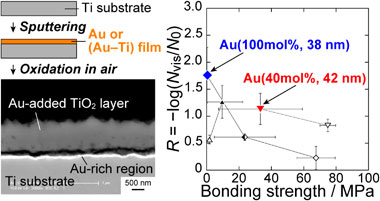
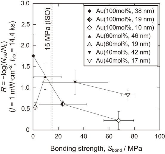
The relationship between antibacterial properties and bonding strength is shown in Fig. 13. The antibacterial properties decreased as the bonding strength increased, except for Au(60 mol%, 19 nm) which exhibited a relatively low bonding strength owing to the formation of oxide nodules as mentioned above. Compared with Au(100 mol%, Lfilm) and Au(60 mol%, Lfilm), the TiO2 layer on Au(40 mol%, Lfilm) possessed a better antibacterial properties-bonding strength balance, providing R > 0.5 and Sbond > 15 MPa. In particular, Au(40 mol%, 42 nm) provided the highest R value among the specimens in the groups with Sbond > 15 MPa: R = 1.1 and Sbond = 33 MPa. Therefore, the coating of Au(40 mol%, 42 nm) can be considered superior for fabricating visible-light-photocatalytically active TiO2 layers on Ti.
For the utilization of visible-light photocatalytically active TiO2 layers in clinical applications, optimization of visible-light irradiation conditions and improvement of bonding strength are mandatory. Nagay et al.22) and Iwatsu et al.21) evaluated the antibacterial properties of TiO2 layers under visible-light irradiation for shorter irradiation times (1.8 and 0.9 ks, respectively) and much stronger light sources (45 and 106 mW·cm−2, respectively). Carbon-dissolved TiO2 layer has been reported to show higher bonding strength (more than 70 MPa)23) than the Au-added TiO2 layers in this study. The evaluation of antibacterial properties with shorter visible-light irradiation times and improvement of bonding strength by preventing the formation of an Au-rich region could be the subjects of future studies on Au-added TiO2 layers.
5. Conclusions
Au-added TiO2 layers were formed by combining Au sputtering and the thermal oxidation of Ti. As the thickness of the Au–Ti sputtered film increased, the oxidation of Ti with the sputtered film was promoted, and the obtained TiO2 layer showed higher antibacterial properties against E. coli under visible-light irradiation. The TiO2 layer formed on Au(100 mol%, 38 nm) exhibited the highest antibacterial activity under visible-light irradiation. This antibacterial activity is comparable to that of the TiO2 layer formed by the thermal oxidation of Ti–5 mol%Au.20) Au-added TiO2 layers showed cytotoxicity against MC3T3-E1 and hGF-1 only under visible-light irradiation but not in the dark. These properties may be beneficial for clinical use.
This study is novel in that combining Au-sputtering and thermal oxidation of Ti was proven to be effective in forming TiO2 layers with antibacterial activity under visible-light irradiation. The improvement of the antibacterial property-bonding strength balance remains a challenge for the clinical application of Au-added TiO2 layers. The Au-added TiO2 layers formed on Au(40 mol%, 42 nm) showed the best antibacterial property-bonding strength balance: R = 1.1 at 1 mW·cm−2 irradiation for 14.4 ks and Sbond = 33 MPa. This balance is still lower than that of the carbon-dissolved TiO2 layers formed by two-step thermal oxidation: R ≈ 2.0 at 1 mW·cm−2 irradiation for 14.4 ks and Sbond > 70 MPa.23) It was revealed that a decrease in the formation of an intermetallic layer at the TiO2 layer/substrate interface is the key to improving the bonding strengths.
Acknowledgments
The authors would like to thank Kazuyo Omura of Tohoku University for the XPS analysis and Maiko Furuya, Kotone Yokota, and Yu-Jie Xiong for the evaluation of cytotoxicity. This work was supported by a Grant-in-Aid for Scientific Research from the Ministry of Education, Culture, Sports, Science, and Technology (MEXT) of Japan (grant numbers 18H01718 and JP21H04603), Grant-in-Aid for JSPS Fellows (grant number JP18J10430), the Light Metal Educational Foundation, Inc., and the Cooperative Research Project Program of Joint Usage/Research Center at the Institute of Development, Aging and Cancer, Tohoku University.
REFERENCES
- 1) P.A. Norowski, Jr. and J.D. Bumgardner: J. Biomed. Mater. Res. Part B Appl. Biomater. 88B (2009) 530–543. doi:10.1002/jbm.b.31152
- 2) M.A. Atieh, N.H.M. Alsabeeha, C.M. Faggion, Jr. and W.J. Duncan: J. Periodontol. 84 (2013) 1586–1598. doi:10.1902/jop.2012.120592
- 3) P.-I. Brånemark, B.O. Hansson, R. Adell, U. Breine, J. Lindström, O. Hallén and A. Öhman: Scand. J. Plast. Reconstr. Surg. Suppl. 16 (1977) 1–132.
- 4) P.-I. Brånemark: J. Prosthet. Dent. 50 (1983) 399–410. doi:10.1016/S0022-3913(83)80101-2
- 5) L. Le Guéhennec, A. Soueidan, P. Layrolle and Y. Amouriq: Dent. Mater. 23 (2007) 844–854. doi:10.1016/j.dental.2006.06.025
- 6) A. Mombelli: Periodontol. 2000 28 (2002) 177–189. doi:10.1034/j.1600-0757.2002.280107.x
- 7) T. Hanawa: Dent. Mater. J. 36 (2017) 533–538. doi:10.4012/dmj.2017-154
- 8) J. Grischke, J. Eberhard and M. Stiesch: Dent. Mater. J. 35 (2016) 545–558. doi:10.4012/dmj.2015-314
- 9) M. Yoshinari, Y. Oda, T. Inoue and M. Shimono: Metall. Mater. Trans. A 33 (2002) 511–519. doi:10.1007/s11661-002-0113-6
- 10) M.F. Kunrath, B.F. Leal, R. Hubler, S.D. de Oliveira and E.R. Teixeira: AMB Express 9 (2019) 51. doi:10.1186/s13568-019-0777-6
- 11) M.C. Cortizo, T.G. Oberti, M.S. Cortizo, A.M. Cortizo and M.A. Fernández Lorenzo De Mele: J. Dent. 40 (2012) 329–337. doi:10.1016/j.jdent.2012.01.008
- 12) J. Wu, K. Ueda and T. Narushima: Mater. Sci. Eng. C 109 (2020) 110599. doi:10.1016/j.msec.2019.110599
- 13) O. Gokcekaya, T.J. Webster, K. Ueda, T. Narushima and C. Ergun: Mater. Sci. Eng. C 77 (2017) 556–564. doi:10.1016/j.msec.2017.03.233
- 14) M. Shimabukuro, H. Tsutsumi, Y. Tsutsumi, T. Manaka, P. Chen, M. Ashida, K. Ishikawa, H. Katayama and T. Hanawa: Dent. Mater. J. 40 (2021) 592–598. doi:10.4012/dmj.2020-188
- 15) M. Shimabukuro, Y. Tsutsumi, K. Nozaki, P. Chen, R. Yamada, M. Ashida, H. Doi, A. Nagai and T. Hanawa: Dent. Mater. J. 39 (2020) 639–647. doi:10.4012/dmj.2019-178
- 16) W. Liu, N.H. Golshan, X. Deng, D.J. Hickey, K. Zeimer, H. Li and T.J. Webster: Nanoscale 8 (2016) 15783–15794. doi:10.1039/C6NR04461A
- 17) M. Godoy-Gallardo, C. Mas-Moruno, M.C. Fernández-Calderón, C. Pérez-Giraldo, J.M. Manero, F. Albericio, F.J. Gil and D. Rodríguez: Acta Biomater. 10 (2014) 3522–3534. doi:10.1016/j.actbio.2014.03.026
- 18) N. Suketa, T. Sawase, H. Kitaura, M. Naito, K. Baba, K. Nakayama, A. Wennerberg and M. Atsuta: Clin. Implant Dent. Relat. Res. 7 (2005) 105–111. doi:10.1111/j.1708-8208.2005.tb00053.x
- 19) M. Kawashita, N. Endo, T. Watanabe, T. Miyazaki, M. Furuya, K. Yokota, Y. Abiko, H. Kanetaka and N. Takahashi: Colloids Surf. B Biointerfaces 145 (2016) 285–290. doi:10.1016/j.colsurfb.2016.05.017
- 20) T. Ueda, K. Ueda, K. Ito, K. Ogasawara, H. Kanetaka, T. Mokudai, Y. Niwano and T. Narushima: J. Biomed. Mater. Res. A 107 (2019) 991–1000. doi:10.1002/jbm.a.36624
- 21) M. Iwatsu, H. Kanetaka, T. Mokudai, T. Ogawa, M. Kawashita and K. Sasaki: J. Biomed. Mater. Res. B Appl. Biomater. 108 (2020) 451–459. doi:10.1002/jbm.b.34401
- 22) B.E. Nagay, C. Dini, J.M. Cordeiro, A.P. Ricomini-Filho, E.D. de Avila, E.C. Rangel, N.C. da Cruz and V.A.R. Barão: ACS Appl. Mater. Interfaces 11 (2019) 18186–18202. doi:10.1021/acsami.9b03311
- 23) T. Ueda, N. Sato, R. Koizumi, K. Ueda, K. Ito, K. Ogasawara and T. Narushima: Dent. Mater. 37 (2021) e37–e46. doi:10.1016/j.dental.2020.10.009
- 24) V. Kumaravel, K.M. Nair, S. Mathew, J. Bartlett, J.E. Kennedy, H.G. Manning, B.J. Whelan, N.S. Leyland and S.C. Pillai: Chem. Eng. J. 416 (2021) 129071. doi:10.1016/j.cej.2021.129071
- 25) H. Aita, N. Hori, M. Takeuchi, T. Suzuki, M. Yamada, M. Anpo and T. Ogawa: Biomaterials 30 (2009) 1015–1025. doi:10.1016/j.biomaterials.2008.11.004
- 26) F. Xiao, K. Tsuru, S. Hayakawa and A. Osaka: Thin Solid Films 441 (2003) 271–276. doi:10.1016/S0040-6090(03)00913-1
- 27) X. Wang, W. Yan, S. Hayakawa, K. Tsuru and A. Osaka: Biomaterials 24 (2003) 4631–4637. doi:10.1016/S0142-9612(03)00357-0
- 28) T. Ueda, S. Sado, K. Ueda and T. Narushima: Mater. Lett. 185 (2016) 290–294. doi:10.1016/j.matlet.2016.08.066
- 29) N. Kruse and S. Chenakin: Appl. Catal. A 391 (2011) 367–376. doi:10.1016/j.apcata.2010.05.039
- 30) Japanese Standards Association: JIS R 1752, (2020).
- 31) R. Sadowski, M. Strus, M. Buchalska, P.B. Heczko and W. Macyk: Photochem. Photobiol. Sci. 14 (2015) 514–519. doi:10.1039/C4PP00270A
- 32) J. O’Brien, I. Wilson, T. Orton and F. Pognan: Eur. J. Biochem. 267 (2000) 5421–5426. doi:10.1046/j.1432-1327.2000.01606.x
- 33) M. Kawashita, M. Hasegawa, T. Kudo, H. Kanetaka, T. Miyazaki and M. Hashimoto: Mater. Sci. Eng. C 69 (2016) 1268–1272. doi:10.1016/j.msec.2016.08.034
- 34) P.M. Kumar, S. Badrinarayanan and M. Sastry: Thin Solid Films 358 (2000) 122–130. doi:10.1016/S0040-6090(99)00722-1
- 35) C.D. Wagner: Photoelectron and Auger Energies and the Auger Parameter: A Data Set, (Practical Surface Analysis, New York, 1990) pp. 595–634.
- 36) C. Wang, C. Liu, J. Chen and T. Shen: J. Colloid Interface Sci. 191 (1997) 464–470. doi:10.1006/jcis.1997.4976
- 37) B. Liu, J. Wang, J. Yang and X. Zhao: Appl. Surf. Sci. 464 (2019) 367–375. doi:10.1016/j.apsusc.2018.09.031
- 38) A. Bzowski and T.K. Sham: J. Vac. Sci. Technol. A 11 (1993) 2153–2157. doi:10.1116/1.578384
- 39) International Organization for Standardization: ISO 13779–2, (2008).
- 40) X.Z. Li and F.B. Li: Environ. Sci. Technol. 35 (2001) 2381–2387. doi:10.1021/es001752w
- 41) S.M. Esfandfard, M.R. Elahifard, R. Behjatmanesh-Ardakanii and H. Kargar: Phys. Chem. Res. 6 (2018) 547–563. doi:10.22036/PCR.2018.128713.1481
- 42) T. Okazumi, K. Ueda, K. Tajima, N. Umetsu and T. Narushima: J. Mater. Sci. 46 (2011) 2998–3005. doi:10.1007/s10853-010-5177-x
- 43) S. Sado, T. Ueda, Y. Tokuda, N. Sato, K. Ueda and T. Narushima: Mater. Trans. 60 (2019) 1814–1820. doi:10.2320/matertrans.ME201901
- 44) M.S. Reddy, J. Sadanandam and S.V. Suryanarayana: J. Mater. Sci. Lett. 2 (1983) 166–168. doi:10.1007/BF00735567
- 45) R.K. Kirby: J. Res. Natl. Bur. Stand. A Phys. Chem. 71A (1967) 363–369. doi:10.6028/jres.071A.041
- 46) P. Hidnert: J. Res. Natl. Bur. Stand. 30 (1943) 101–105. doi:10.6028/jres.030.008