Abstract
Additive manufacturing (AM) has been attracting a great deal of attention in both academia and industry in recent years as a technology that could bring innovation to manufacturing. AM was originally developed as a method specialized in fabricating three-dimensional structures by the additive manner. However, in reality, a huge number of parameters involved in AM has a significant effect on the microstructure and the resulting physicochemical properties of the metallic material. Therefore, in very recent years, metal AM is being recognized as a technology for controlling the microstructure of metals rather than its shape. In addition, AM can even customize the microstructure of each site by applying locally controlled heat energy. The ability to simultaneously control complex shapes and microstructures will add even higher value to light-weight metal materials. This paper describes the potential of metal AM to control material and shape properties that dictates the essential mechanical properties of the product with introducing latest results.
This Paper was Originally Published in Japanese in J. JILM 72 (2022) 327–333. The title was changed due to the addition of “Review—”.
1. Introduction
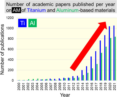
Metal additive manufacturing (AM), or metal 3D printing, can overcome many of the challenges associated with mass production using traditional subtractive methods. For instance, AM facilitates the manufacture of complicated shapes, flexible customization of structure, and significant weight reduction without compromising strength. Consequently, AM has attracted considerable interest in both academia and industry in recent years.1,2) Furthermore, using AM, geometrically complex patterns such as (near) net shapes can be obtained in a single step by literally “printing” metal in voxel units (pixels in one layer). These attributes of metal AM could help in the realization of a carbon-neutral society and accelerate the implementation of AM on a global scale. The development of topology optimization technology3) has further supported this. Today, AM of light metal materials is expanding year by year. Figure 1 shows the number of academic papers published per year on AM of aluminum and titanium-based materials since 2000. Since magnesium is often included as an additive element in aluminum alloys, we have excluded papers reporting on them from our search to guarantee accuracy of search. It is evident from the figure that there has been a remarkable increase in the number of papers published in recent years, especially from around 2014, showing the global prosperity of light metal AM research. This is presumably because of former US President Obama’s State of the Union address in the year 2013, in which he mentioned that “3D printing has the potential to revolutionize the way we make almost everything”. One could presume that this triggered a global AM boom and caused a rapid expansion of the field of light metal AM.

Among the various metal AM processes, powder bed fusion (PBF) is the most commonly used method. Laser PBF (L-PBF; using a laser as a heat source) and electron beam PBF (EB-PBF; using an electron beam as a heat source) are the mainstream PBF methods. PBF uses a heat source with a relatively small spot diameter on fine powder of raw material to create a minute molten pool, thereby achieving high shape accuracy. The formation of such a minute molten pool causes a periodic thermal history owing to the abrupt melting and solidification of the metal and repeated lamination. Furthermore, according to recent discoveries, PBF affords a specific metallographic structure that cannot be obtained by conventional methods such as casting and forging. In a nut shell, metal AM can be utilized in future manufacturing as a technology that has the potential to ‘create’ internal microstructures unachievable from other technologies, as well as produce three-dimensional shapes with high accuracy including surface accuracy.
This paper reviews the microstructure that dictates the essential part of mechanical properties of the product, in addition to the shape property. The microstructural development that is unique to PBF of light metal materials is described introducing latest results.
2. AM for Light Metal Materials: Overview
As mentioned above, the most commonly produced materials using AM for light metal materials are titanium alloys and aluminum alloys. Although there have been papers reporting on magnesium alloys, they are relatively few in number.
The most commonly manufactured titanium alloy using AM is the (α + β)-type Ti–6Al–4V alloy, and it is extensively studied owing to its utility as a biomaterial and an aerospace material.4,5) Tuning the mechanical properties of materials using structuring uniquely achievable by the PBF method has already been reported.6,7) From a microstructural perspective, the Ti–6Al–4V alloy undergoes a phase transformation from the bcc-β phase to the hcp-α (α′) phase when cooled; 12 variants in the Burgers relationship are selected in a relatively random manner. Furthermore, for the Ti–6Al–4V alloy, structure size change and martensite (α′) phase formation as a function of the cooling rate,8,9) changes in structure/phase composition due to repeated thermal history peculiar to AM,5) non-uniformity in members,10) etc. have been extensively investigated. β-type titanium alloys basically do not undergo phase transformation to the α phase during quenching. Therefore, unlike in the case of Ti–6Al–4V alloy, the crystal orientation of the β phase in such alloys is maintained during solidification. Our research group is the first to succeed in controlling the crystal orientation of β-type titanium alloys centered on Ti–15Mo–5Zr–3Al alloys.11–15) However, in the case of an alloy containing an unstable β phase, phase transformation may occur owing to the thermal history14) during fabrication and generation of residual stress.16,17)
There have been a few reports on manufacturing aluminum alloys using EB-PBF, owing to the over-aging during fabrication and remarkable evaporation of alloying elements (zinc and magnesium in particular vaporize at a temperature lower than the melting temperature of aluminum) due to melting in vacuum.18,19) However, aluminum alloys are relatively difficult to manufacture using L-PBF because of their high reflectance (low laser energy absorption rate) and high thermal conductivity toward fiber lasers. Wire and arc additive manufacturing (WAAM), which uses arc discharge as a heat source, has also been employed,20) but the method necessitates secondary processing after fabrication. For manufacturing aluminum alloys using the L-PBF method, Al–Si alloys (AlSi10Mg, AlSi12, etc.) are often used.21,22) High-strength alloys such as the 2000, 5000, 6000, and 7000 series are well-suited for applications in the aerospace and automobile industry. However, in these L-PBF fabrications, crack generation during fabrication owing to rapid cooling becomes a problem.23) In recent years, new alloys for L-PBF such as SCALMALLOY® 24) and Addalloy®,25) which are based on 5000 and 7000 series alloys and have incorporated scandium and zirconium, have been developed. Scandium improves weldability and reduces the probability of hot cracks.26) From a microstructural perspective, the formation of a bimodal structure with fine equiaxed grains at the bottom of the molten pool and elongated grains extending toward the center of the molten pool is a common feature of aluminum alloys.27,28) The existence of intermetallic compound particles inside the fine equiaxed particles suggests that they act as a nucleation site to generate randomly oriented equiaxed grains. The major axes of the elongated grains are oriented along the ⟨100⟩ direction (approximately opposite to the heat flow).28)
Magnesium alloys are particularly reactive toward oxygen and nitrogen and pose a high risk of ignition and explosion. Therefore, there exist very few studies of manufacturing them with PBF using their powders as raw materials, when compared to titanium and aluminum alloys. However, WE43, AZ61, ZK61, Mg–Ca alloy, etc., used mainly as bioabsorbable porous materials, are made using L-PBF.29) Only a few reports exist on the microstructural control of these alloys. However, it has been reported that grain growth due to the influence of repeated thermal history might lead to crystal orientation.30)
For TiAl31–33) and high entropy alloys containing light metals,34) microstructural control via metal AM, especially the PBF method, and the associated high functionality have been achieved.
3. Formation of Single Crystalline-Like Microstructure
One of the greatest characteristics of AM of metals, especially PBF, is the formation of a strong crystallographic texture on metallic materials.35–37) The crystal texture causes anisotropy of mechanical properties such as Young’s modulus, yield stress, and wear resistance. For example, in single crystals of some β-type titanium alloys, especially alloys with a small average valence electron number per atom e/a (e: total number of valence electrons, a: total number of atoms), which is close to 4, the Young’s modulus drops to approximately 40 GPa along the ⟨100⟩ direction, due to anisotropy.38,39) This is expected to suppress stress shielding and could be relevant when considering the material for application as a bone implant. From the solidification map40) shown in Fig. 2, in order to obtain a single crystal, it is necessary to suppress the occurrence of compositional supercooling. This can be done by increasing the temperature gradient G at the solid-liquid interface and by keeping the solid-liquid interface migration rate R small, to realize solidification conditions located above the line corresponding to Columnar-Equiaxed Transition (CET). For instance, the floating zone method produces single crystals by moving the solid-liquid interface at a low speed of several mm/h (10−4–10−3 mm/s). In contrast, in L-PBF, the solid-liquid interface migrates at high speed, owing to the travel speed of heat source (∼103 mm/s). However, the extremely large temperature gradient (∼103 K/mm) ensures flat interface migration, and strong crystallographic texture can be obtained through epitaxial growth by stabilizing the crystal orientation. These aspects are described in detail in the next section.

Figure 3(a), (b) shows the inverse pole figure (IPF) map and {100} pole figure of the Ti–15Mo–5Zr–3Al alloy fabricated using L-PBF by scan strategy (SS)_X and SS_XY.11,14) A single crystalline-like texture forms in both cases. In L-PBF, ⟨011⟩ is preferentially oriented in the building direction and ⟨100⟩ in the scanning direction in SS_X, and ⟨100⟩ is preferentially oriented in both the building and scanning directions in SS_XY.11,14) These crystallographic textures are respectively referred to as {011}z⟨100⟩x and {001}z⟨100⟩x. This scan strategy-dependent crystal orientation is similar to what is observed for nickel-based and iron-based alloys with an fcc structure.35,41)
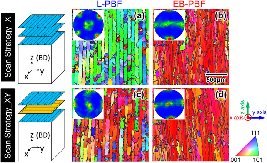
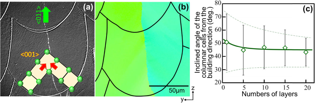
Figure 4(a), (b) shows the optical microscopy image and IPF map along the yz-cross section (vertical plane to the laser scanning direction) of a Ti–15Mo–5Zr–3Al product prepared by SS_X after chemical etching. The cross-sectional shape of each melt pool can be clearly seen. The optical microscopy image reveals the cellular microstructure based on rapid solidification. Furthermore, the elongation direction of the cell, i.e., the solid-liquid interface migration direction, is almost in the cross section of the melt pool; the cell elongation direction coincides with ⟨001⟩. Furthermore, the cell elongation direction differs for the left and right halves of the melt pool, and each half lies at an angle of approximately ±45° with respect to the building direction; the solid-liquid interfaces from the left and right meet at the central part of the melt pool at an angle of approximately 90°. Consequently, grain boundaries with a small misorientation are formed in the xz-plane at the center of the melt pool. In other words, in LPBF, the crystal orientation is adjusted during the layer-by-layer solidification process, with the driving force being the reduction in interfacial energy accompanying the reduction in crystallographic misorientation at the grain boundaries formed at the melt pool center. In fact, a quantitative analysis of the angle between the cell elongation direction and the building direction in the yz-cross section at the initial stage of fabrication reveals that the cell elongation direction converges along the 45° direction with the increase in the number of layers (Fig. 4(c)).13) From this, it follows that in one melt pool, the orientation is stabilized ⟨011⟩ in the building direction, ⟨100⟩ in the scanning direction, and ⟨011⟩ in the direction perpendicular to the scanning direction in the scanning plane.
Further proof of the formation of the single crystalline-like texture using the reduction of crystal misorientation as a driving force in β-type titanium alloys can be found by approximating the solid-liquid interface movement in the melt pool to be two-dimensional in its cross section. Figure 5 shows a simulation of the temperature distribution of Ti–15Mo–5Zr–3Al alloy during laser scanning based on heat conduction and heat transfer; specifically, the thermophysical properties of the titanium alloy and the parameters related to the laser heat source are used. Figure 5(a) shows the longitudinal cross-sectional image of the melt pool; the melt pool is shown in red and has a long tail. Figure 5(b) shows that the heat flow direction at the solid-liquid interface is almost vertically downward. This allows for a two-dimensional heat flow within the cross section of the melt pool and the resulting solid-liquid interface movement (Fig. 5(c)). The formation of such a melt pool with a long tail is characteristic of a metal with a relatively low thermal conductivity, and the formation of crystal orientation in such metals follows the same mechanism as that of this β-type titanium alloy.35,41)

Unlike SS_X in L-PBF, SS_XY changes the laser scanning direction from x direction (in the melt pool, ⟨100⟩//x and ⟨011⟩//y are stable) to y direction (similarly, ⟨100⟩//y and ⟨011⟩//x are stable) and vice versa. This resulted in the formation of the texture {001}z⟨100⟩x by the competition of crystal growth between ⟨100⟩ in the solidified part and ⟨011⟩ in the previous layer in the laser scanning direction. As the growth rate of ⟨100⟩ is greater than ⟨011⟩,42) ⟨100⟩ remains in the scanning direction while ⟨011⟩ is eliminated, resulting in ⟨100⟩ orientation in two scanning directions (x, y directions) and thus along the z direction.13) As in the case of SS_X, the crystallographic texture is stabilized by reducing the crystal misorientation at the solid-liquid interface at the cross section of the melt pool.
3.2 Change in crystallographic orientation depending on the melt pool shape
In L-PBF, the crystal orientation changes with the scan strategy, whereas in EB-PBF, the {001}z⟨100⟩x texture is formed independently of the scan strategy (Fig. 3(c), (d)).14) This difference of outcome originates from the difference in the shape of the melt pool, which in turn stems from the difference in the output of the electron beam and laser and the conversion mode to heat.14) Upon irradiating the material with laser, the light energy is converted into heat through the movement of electrons on the irradiated surface, and the heat generated diffuses inside by heat conduction, and ablates the surface to form a characteristic keyhole. Consequently, the melt pool in L-PBF has a “narrow and deep” shape in many cases. In contrast, electron beams have a higher conversion efficiency as the kinetic energy of electrons is directly converted into lattice vibration energy. Furthermore, since the beam output is generally larger (laser: several hundred watts, electron beam: several kW), the energy input to the metal is large, and hence the EB-PBF creates a “wide and shallow” melt pool. The difference in the melt pool shape by the two techniques is evident from the cross section of the top part of the build (Fig. 6(a), (b)). In the wide and shallow melt pool in EB-PBF, the heat flow direction in the cross section of the melt pool is vertically downward, and ⟨100⟩ growth in the building (z) direction occurs independently of the scan strategy.
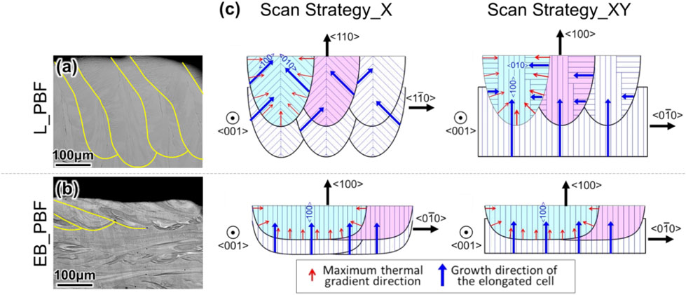
Hence, the crystal orientation can be changed by altering the melt pool shape, which in turn can be achieved by the appropriate choice of the afore-mentioned heat source types and PBF process parameters such as the factors related to heat source irradiation (output P, scanning speed v, scanning interval d, layer thickness t, etc.). For example, by enlarging the radius of curvature of the melt pool bottom, a crystallographic lamellar structure in which the ⟨100⟩//z-oriented layers are stacked between the ⟨011⟩//z-oriented layers that are unique to SS_X, can be achieved using L-PBF. Depending on the strain transfer efficiency at the lamellar interface (grain boundary), the anisotropic interface of this structure acts as a barrier to the transmission of dislocations, thereby strengthening the products.35,41)
4. Polycrystalline Structure Formation
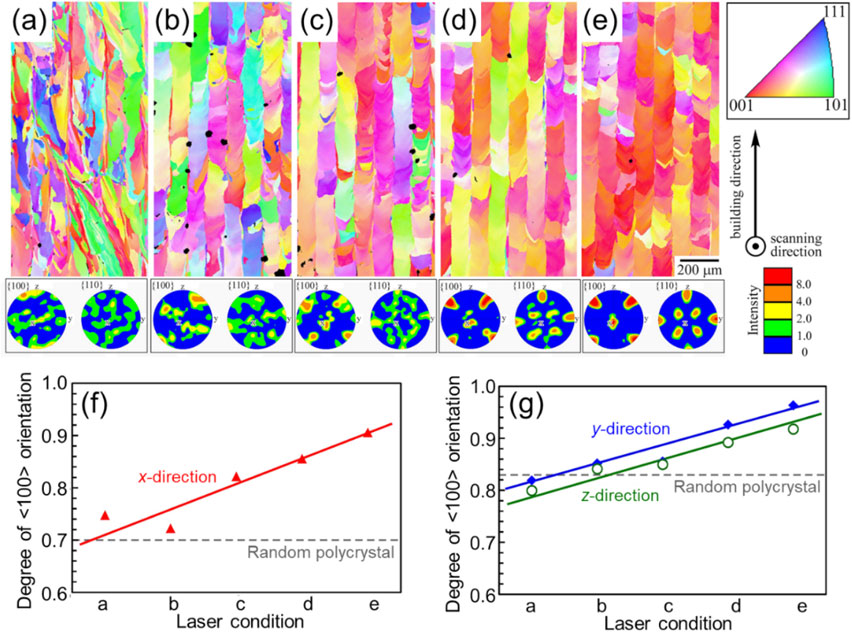
Equiaxed grains form by increasing the compositional supercooling and thus nucleation frequency in the condition where G is small and R is large (lower right of solidification map (Fig. 2)), leading to polycrystallization. Considering the relationship between the fabrication parameters in PBF and G and R, a decrease in output P and an increase in scanning speed v lead to a low G and high R.41) However, low output and high scanning speed represent the significantly reduced input energy density (E = P/(vdt)), and in actual PBF, the fabricated parts become porous thereby reducing the density owing to insufficient melting, rather than polycrystalline formation. However, it is possible to obtain a polycrystalline structure with relatively isotropic crystal orientation by laser scanning using conditions under which the two-dimensional solid-liquid interface migration in the cross section of the melt pool is not established, as shown in Section 3.1 and Fig. 5. Specifically, the polycrystalline is achieved by shortening the tail of the melt pool and maintaining a large inclination of the bottom of the melt pool along the scanning direction. Such a melt pool is realized by scanning the heat source at a low speed. Figure 7(a)–(e) shows the IPF map of the Ti–15Mo–5Zr–3Al alloy, demonstrating the changes in its texture when the scanning speed is varied at a fixed energy density;15,43) the scanning speed increases from panels a to e. It is clear from the IPF map, pole figure (Fig. 7(a)–(e)), and degree of crystal orientation in each direction (Fig. 7(f), (g)) that the lower the scanning speed, the more random the crystal orientation, and hence, the more polycrystalline the samples become. Increasing the slope at the bottom of the melt pool is intended to disperse the heat flow direction and the resulting ⟨100⟩ growth direction, along various directions without limiting it within the two-dimensional plane shown in Fig. 5(c) inside the melt pool. Consequently, the driving force for forming a single crystalline-like structure at the interfaces where the solidification fronts encounters13) is lost, and the degree of crystal orientation is reduced.
5. Bimodal Microstructure Formation
The polycrystalline formation described in the previous section can also be achieved by uniformly dispersing the nucleation sites inside the melt pool. If there is a phase with high melting point in the solidified part, it may remain in the melt pool without melting during remelting by the heat input for the next layer, and equiaxed grains could form with it as the nucleus. However, as temperature increases toward the top of the melt pool, the high melting point phase also melts. Therefore, these equiaxed grains exist only at the bottom of the melt pool, and the upper part of the melt pool forms relatively coarse elongated grains that grow radially toward the center of the melt pool depending on heat flow. As a result, a bimodal structure that exhibits two grain morphologies and orientations forms. Figure 8 shows an example of the bimodal structure of the aluminum alloy containing the L12 precipitate. The black part in Fig. 8(a) corresponds to the bottom of the melt pool, and Fig. 8(b) shows the fine equiaxed grains. There are submicron-sized L12 precipitate particles inside the equiaxed grains. Microstructures with such a bimodal particle size distribution contribute to the development of excellent strength-ductility balance.44,45)

6. Conclusion
Additive manufacturing or 3D printing was originally developed as a method specialized in manufacturing 3D shapes by the additive manner. Therefore, the AM method is chosen on the basis of the required shape/size of parts, surface accuracy, and manufacturing speed. However, in reality, the magnitude and direction of the temperature gradient, the migration speed and direction of the solid-liquid interface, and the resulting thermal history are significantly influenced by various parameters such as type, power, and scanning speed of heat source, layer thickness, and preheating condition, all of which has a significant effect on the microstructure and the resulting physicochemical properties of the metallic material. Even solidification behavior and microstructure development behavior beyond the scope of conventional solidification theory are beginning to be discovered. Therefore, in recent years, metal AM is being recognized as a technology for controlling the microstructure of metals rather than its shape, or as a methodology for simultaneously controlling the shape as well as microstructure. In addition, AM can even customize the microstructure of each site by applying locally controlled heat energy. The ability to simultaneously control complex shapes and microstructures will add even higher value to light-weight metal materials, and AM is expected to become an important technology that will lead the manufacturing of light-weight metals in the near future.
Acknowledgments
This work was supported by a Grant-in-Aid for Scientific Research (JP18H05254) from the Japan Society for the Promotion of Science (JSPS) and CREST-Nanomechanics: Elucidation of macroscale mechanical properties based on understanding nanoscale dynamics of innovative mechanical materials (Grant Number: JPMJCR2194) from the Japan Science and Technology Agency (JST). Part of this content was also supported by a 1st Frontier Research Grant from the Japan Institute of Metals.
REFERENCES
- 1) D. Herzog, V. Seyda, E. Wycisk and C. Emmelmann: Acta Mater. 117 (2016) 371–392. doi:10.1016/j.actamat.2016.07.019
- 2) T. DebRoy, H.L. Wei, J.S. Zuback, T. Mukherjee, J.W. Elmer, J.O. Milewski, A.M. Beese, A. Wilson-Heid, A. De and W. Zhang: Prog. Mater. Sci. 92 (2018) 112–224. doi:10.1016/j.pmatsci.2017.10.001
- 3) S. Mukherjee, D. Lu, B. Raghavan, P. Breitkopf, S. Dutta, M. Xiao and W. Zhang: Arch. Comput. Methods Eng. 28 (2021) 4549–4571. doi:10.1007/s11831-021-09544-3
- 4) T. Nakano and T. Ishimoto: KONA Powder Part. J. 32 (2015) 75–84. doi:10.14356/kona.2015015
- 5) Z. Liu, B. He, T. Lyu and Y. Zou: JOM 73 (2021) 1804–1818. doi:10.1007/s11837-021-04670-6
- 6) N. Ikeo, T. Ishimoto and T. Nakano: J. Alloy. Compd. 639 (2015) 336–340. doi:10.1016/j.jallcom.2015.03.141
- 7) N. Ikeo, H. Fukuda, A. Matsugaki, T. Inoue, A. Serizawa, T. Matsuzaka, T. Ishimoto, R. Ozasa, O. Gokcekaya and T. Nakano: Crystals 11 (2021) 959. doi:10.3390/cryst11080959
- 8) J. Yang, H. Yu, J. Yin, M. Gao, Z. Wang and X. Zeng: Mater. Des. 108 (2016) 308–318. doi:10.1016/j.matdes.2016.06.117
- 9) H. Amano, T. Ishimoto, R. Suganuma, K. Aiba, S.-H. Sun, R. Ozasa and T. Nakano: Addit. Manuf. 48 (2021) 102444. doi:10.1016/j.addma.2021.102444
- 10) P. Wang, X. Tan, M.L.S. Nai, S.B. Tor and J. Wei: Mater. Des. 95 (2016) 287–295. doi:10.1016/j.matdes.2016.01.093
- 11) T. Ishimoto, K. Hagihara, K. Hisamoto, S.-H. Sun and T. Nakano: Scr. Mater. 132 (2017) 34–38. doi:10.1016/j.scriptamat.2016.12.038
- 12) T. Nagase, T. Hori, M. Todai, S.-H. Sun and T. Nakano: Mater. Des. 173 (2019) 107771. doi:10.1016/j.matdes.2019.107771
- 13) T. Ishimoto, K. Hagihara, K. Hisamoto and T. Nakano: Addit. Manuf. 43 (2021) 102004. doi:10.1016/j.addma.2021.102004
- 14) S.-H. Sun, K. Hagihara, T. Ishimoto, R. Suganuma, Y.-F. Xue and T. Nakano: Addit. Manuf. 47 (2021) 102329. doi:10.1016/j.addma.2021.102329
- 15) K. Hagihara and T. Nakano: JOM 74 (2022) 1760–1773. doi:10.1007/s11837-021-04966-7
- 16) A. Takase, T. Ishimoto, R. Suganuma and T. Nakano: Scr. Mater. 201 (2021) 113953. doi:10.1016/j.scriptamat.2021.113953
- 17) A. Takase, T. Ishimoto, R. Suganuma and T. Nakano: Addit. Manuf. 47 (2021) 102257. doi:10.1016/j.addma.2021.102257
- 18) T. Mahale, D. Cormier, O. Harrysson and K. Ervin: 18th solid freeform fabrication symposium, (2007) pp. 312–323.
- 19) V.R. Utyaganova, A.V. Filippov, N.N. Shamarin, A.V. Vorontsov, N.L. Savchenko, S.V. Fortuna, D.A. Gurianov, A.V. Chumaevskii, V.E. Rubtsov and S.Y. Tarasov: Int. J. Adv. Manuf. Technol. 108 (2020) 2823–2838. doi:10.1007/s00170-020-05539-9
- 20) M.M. Tawfik, M.M. Nemat-Alla and M.M. Dewidar: J. Mater. Res. Technol. 13 (2021) 754–768. doi:10.1016/j.jmrt.2021.04.076
- 21) N.T. Aboulkhair, M. Simonelli, L. Parry, I. Ashcroft, C. Tuck and R. Hague: Prog. Mater. Sci. 106 (2019) 100578. doi:10.1016/j.pmatsci.2019.100578
- 22) J. Zhang, B. Song, Q. Wei, D. Bourell and Y. Shi: J. Mater. Sci. Technol. 35 (2019) 270–284. doi:10.1016/j.jmst.2018.09.004
- 23) T. Qi, H. Zhu, H. Zhang, J. Yin, L. Ke and X. Zeng: Mater. Des. 135 (2017) 257–266. doi:10.1016/j.matdes.2017.09.014
- 24) https://www.apworks.de/scalmalloy (accessed: 2021.10.21).
- 25) https://www.nanoal.com/addalloy-powder-additive-manufacturing (accessed: 2021.10.21).
- 26) A.B. Spierings, K. Dawson, M. Voegtlin, F. Palm and P.J. Uggowitzer: CIRP Ann. 65 (2016) 213–216. doi:10.1016/j.cirp.2016.04.057
- 27) N. Takata, H. Kodaira, K. Sekizawa, A. Suzuki and M. Kobashi: Mater. Sci. Eng. A 704 (2017) 218–228. doi:10.1016/j.msea.2017.08.029
- 28) Y. Ekubaru, O. Gokcekaya, T. Ishimoto and T. Nakano: Mater. Des. 221 (2022) 110976. doi:10.1016/j.matdes.2022.110976
- 29) N. Sezer, Z. Evis and M. Koç: J. Magn. Alloy. 9 (2021) 392–415. doi:10.1016/j.jma.2020.09.014
- 30) F. Bär, L. Berger, L. Jauer, G. Kurtuldu, R. Schäublin, J.H. Schleifenbaum and J.F. Löffler: Acta Biomater. 98 (2019) 36–49. doi:10.1016/j.actbio.2019.05.056
- 31) K. Cho, H. Kawabata, T. Hayashi, H.Y. Yasuda, H. Nakashima, M. Takeyama and T. Nakano: Addit. Manuf. 46 (2021) 102091. doi:10.1016/j.addma.2021.102091
- 32) K. Cho, R. Kobayashi, J.Y. Oh, H.Y. Yasuda, M. Todai, T. Nakano, A. Ikeda, M. Ueda and M. Takeyama: Intermetallics 95 (2018) 1–10. doi:10.1016/j.intermet.2018.01.009
- 33) M. Todai, T. Nakano, T. Liu, H.Y. Yasuda, K. Hagihara, K. Cho, M. Ueda and M. Takeyama: Addit. Manuf. 13 (2017) 61–70. doi:10.1016/j.addma.2016.11.001
- 34) T. Ishimoto, R. Ozasa, K. Nakano, M. Weinmann, C. Schnitter, M. Stenzel, A. Matsugaki, T. Nagase, T. Matsuzaka, M. Todai, H.-S. Kim and T. Nakano: Scr. Mater. 194 (2021) 113658. doi:10.1016/j.scriptamat.2020.113658
- 35) S.-H. Sun, T. Ishimoto, K. Hagihara, Y. Tsutsumi, T. Hanawa and T. Nakano: Scr. Mater. 159 (2019) 89–93. doi:10.1016/j.scriptamat.2018.09.017
- 36) T. Ishimoto, S. Wu, Y. Ito, S.-H. Sun, H. Amano and T. Nakano: ISIJ Int. 60 (2020) 1758–1764. doi:10.2355/isijinternational.ISIJINT-2019-744
- 37) O. Gokcekaya, N. Hayashi, T. Ishimoto, K. Ueda, T. Narushima and T. Nakano: Addit. Manuf. 36 (2020) 101624. doi:10.1016/j.addma.2020.101624
- 38) M. Tane, S. Akita, T. Nakano, K. Hagihara, Y. Umakoshi, M. Niinomi and H. Nakajima: Acta Mater. 56 (2008) 2856–2863. doi:10.1016/j.actamat.2008.02.017
- 39) S.-H. Lee, M. Todai, M. Tane, K. Hagihara, H. Nakajima and T. Nakano: J. Mech. Behav. Biomed. Mater. 14 (2012) 48–54. doi:10.1016/j.jmbbm.2012.05.005
- 40) P.A. Kobryn and S.L. Semiatin: JOM 53 (2001) 40–42. doi:10.1007/s11837-001-0068-x
- 41) O. Gokcekaya, T. Ishimoto, S. Hibino, J. Yasutomi, T. Narushima and T. Nakano: Acta Mater. 212 (2021) 116876. doi:10.1016/j.actamat.2021.116876
- 42) R.W. Messler: Principles of Welding, (Wiley, New York, 2008).
- 43) T. Ishimoto, J. Yasutomi, S. Sugimoto and T. Nakano: J. Smart Process. 7 (2018) 229–232. doi:10.7791/jspmee.7.229
- 44) R. Ma, C. Peng, Z. Cai, R. Wang, Z. Zhou, X. Li and X. Cao: J. Alloy. Compd. 815 (2020) 152422. doi:10.1016/j.jallcom.2019.152422
- 45) J.R. Croteau, S. Griffiths, M.D. Rossell, C. Leinenbach, C. Kenel, V. Jansen, D.N. Seidman, D.C. Dunand and N.Q. Vo: Acta Mater. 153 (2018) 35–44. doi:10.1016/j.actamat.2018.04.053
- 46) R. Rai, P. Burgardt, J. Milewski, T. Lienert and T. DebRoy: J. Phys. D 42 (2009) 025503. doi:10.1088/0022-3727/42/2/025503
- 47) W. Kurz, C. Bezençon and M. Gäumann: Sci. Technol. Adv. Mater. 2 (2001) 185–191. doi:10.1016/S1468-6996(01)00047-X
- 48) T. Todo, T. Ishimoto, O. Gokcekaya, J. Oh and T. Nakano: Scr. Mater. 206 (2022) 114252. doi:10.1016/j.scriptamat.2021.114252