Abstract
Ti–6Al–4Nb–4Zr (mass%) was prepared by selective laser melting (SLM) under various conditions, and the microstructure evolution resulting from SLM processing and subsequent heat treatments was investigated. The effects of the unique SLM-induced microstructure on the high-temperature compressive strength and creep properties of the samples were then elucidated. Under rapid cooling conditions, the martensitic structure formed in a scale-like pattern, with a 100 µm in size, consistent with the laser scanning pattern. By contrast, under slow cooling conditions, the α/β lamellar structure formed in β grains with a 300 µm grain size instead of in a scale-like pattern. The martensitic structure drastically changed to a Widmanstätten structure during heat treatment. The equiaxed α phase also formed at the interface of the scale-like patterns. By contrast, the α/β lamellar structure did not exhibit a change in response to heat treatment. The compressive strength of the SLM samples was governed by the martensite α size and the grain size, both of which depended on the cooling rate. The dominant creep deformation mechanism at 600°C and under a loading stress of 137 MPa was grain boundary sliding. The creep life depended on the grain size. The HIP treatment improved the creep life because it eliminated pores introduced by the SLM process.
1. Introduction
Additive manufacturing (AM) is a well-known processing method to fabricate three-dimensional complex structures via layer-by-layer deposition and to produce metallic materials via melting by rapid heating and solidification by rapid cooling.1,2) Researchers have focused on two main processing categories—selective laser melting (SLM) and electron beam melting (EBM)—as powder-bed fusion processing methods.2) The difference between SLM and EBM is the heat source, where a laser is used for SLM and an electron beam for EBM. The AM steps are the same in the two methods; however, compared with the powder temperature in SLM, that in EBM is much higher, between approximately 500 and 800°C, which is achieved by preheating the chamber.3) In addition, as a result of the deeper penetration and higher energy of the electron beam compared with those of the laser used in SLM, the cooling rate in EBM is lower than that in SLM.3)
High-temperature Ti alloys are used in compressor disks and blades in aerospace applications because of their high specific strength at high temperatures and good oxidation resistance.4) However, machining of Ti alloys is difficult and expensive because of their low thermal conductivity.5) Because only a small amount of machining is required for near-net-shape products, AM processing has been applied to Ti alloys to obtain such products.2,6) Numerous investigations of AM processing have been performed for Ti–6Al–4V, which is the most widely used commercial Ti alloy. Ti–6Al–4V consists of the hcp-α phase and bcc-β phase.4,5) In general, the microstructure of AM samples is a martensitic α phase formed by phase transformation from the β phase during rapid cooling. Whether the martensitic structure forms depends on the cooling rate. If the cooling rate is greater than 410°C s−1, the martensitic structure forms; by contrast, if the cooling rate is lower than 20°C s−1, the plate-like α phase forms.7)
Because the mechanical properties of Ti alloys are governed by their microstructure, extensive research has been performed on Ti–6Al–4V to improve its ductility and strength at room temperature using AM.1,2) Compared with the mechanical properties at room temperature, research into the high-temperature mechanical properties remains limited.
Other authors have investigated the creep properties of the Ti–6Al–4V martensitic structure in as-prepared samples obtained by SLM in the temperature range between 450 and 900°C.8,9) A change in the microstructure from a martensitic structure to a Widmanstätten structure was observed during creep tests at temperatures greater than 600°C.8) The creep lives for the SLM specimens with the martensitic structure and forged specimens with bimodal and equiaxed structures were found to be similar.9) The creep deformation mechanism changed from dislocation-dominated creep at lower temperatures to diffusive creep deformation at higher temperatures.9)
The effect of heat treatment on the creep properties of Ti–6Al–4V have also been investigated.10,11) The martensitic phase was observed to change to a Widmanstätten structure upon heat treatment at 74010) or 1040°C11) because of coarsening of the martensitic structure. Creep tests were performed at 500,10,11) 600,10) and 650°C,10) and the authors concluded that the creep was controlled by the dominant constituent phase (i.e., the α phase) irrespective of its morphology (e.g., the Widmanstätten structure in SLM specimens and the equiaxed α phase and the bimodal structure in forged specimens).10) Thus, the relationship between the minimum creep rate and the applied stress was similar between the forged and SLM specimens. However, they also found that the creep strain was relatively lower in the heat-treated specimen than in the as-prepared specimens.11) The creep deformation mechanisms of as-prepared and heat-treated specimens were determined to be a grain boundary sliding mechanism and a dislocation glide mechanism, respectively.11)
In previous investigations, various creep conditions were used to investigate creep deformation mechanisms; however, only one processing or heat-treatment condition was selected for sample preparation. The relationship among the processing conditions, microstructure, and mechanical properties has not been clarified. Therefore, in the present study, to identify the relationship between AM processing conditions, microstructure, and high-temperature mechanical properties of Ti alloys, the microstructure changes under various processing and heat-treatment conditions were investigated. Because the cooling rate in SLM is faster than that in EBM,1,2) SLM processing is expected to result in a drastic change in the microstructure of a specimen. Therefore, in the present study, SLM was used to substantially change the microstructure. In addition, high-temperature strength and creep properties of samples with different microstructures were investigated and the mechanical properties were discussed with microstructure related to the SLM processing conditions.
In the present study, Ti–6Al–4Nb–4Zr (mass%) was selected instead of Ti–6Al–4V, which has already been investigated widely. Our group developed Ti–6Al–4Nb–4Zr to improve the oxidation resistance at temperatures greater than 600°C by adding Nb and Zr to near-α alloys similar to Ti–6Al–4V.12–16) The microstructural evolution and high-temperature mechanical properties of Ti–6Al–4Nb–4Zr have already been investigated using forged samples.12–16) We therefore also characterized the difference in the Ti–6Al–4Nb–4Zr microstructures between SLM samples and forged samples and clarified the effect of the microstructure on the samples’ high-temperature mechanical properties.
2. Experimental Procedure
Powdered Ti–6Al–4Nb–4Zr (mass%) alloy (Taniobis) with an average particle size of 30 µm was used for SLM. Specimens with dimensions of 14 × 14 × 50 mm3 were fabricated using a metal laser melting system (EOSINT M290, EOS). A Yb fiber laser (oscillation wavelength: 1030–1070 nm) was used for the fabrication process. The laser was scanned in a zigzag direction for each layer by rotating the direction 90°. To prevent oxidation of the specimens, an Ar gas atmosphere was used inside the chamber. Four different sets of SLM conditions (A–D) were used, as shown in Table 1.
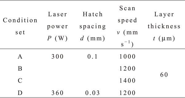
Table 1 SLM processing conditions.
The layer thickness was fixed at 60 µm. Under condition sets A, B, and C, the laser power and hatch spacing were fixed at 300 W and 0.1 mm, respectively, and the scanning speed was varied from 1000 to 1400 mm·s−1.
The solidification rate R depends on the thermal gradient G and cooling rate $\frac{\partial T}{\partial t}$ according to the following equation:17)
| \begin{equation}
R = \frac{1}{G}\frac{\partial T}{\partial t}
\end{equation}
| (1) |
When the laser power is fixed, increasing the laser scan speed increases the solidification rate and the thermal gradient, resulting in an increase of the cooling rate.
17) The exact cooling rate cannot be calculated because of a lack of information about the solidification rate and the thermal gradient; in general, however, according to
eq. (1), the cooling rate increased from condition set A to condition set C. The scanning speed in condition set D was 1200 mm·s
−1, which is the same as that under condition set B; however, the laser power under condition set D was greater than that under condition set B. When the laser power was increased at a fixed scanning speed, the thermal gradient decreased, resulting in a decrease in the cooling rate according to
eq. (1). The cooling rate under condition set D was then lower than that under condition set B.
The energy density E (J·mm−3) input by the laser was calculated using eq. (2):18)
| \begin{equation}
E = \frac{P}{vdt}
\end{equation}
| (2) |
where
P (W) is the laser power,
v (mm·s
−1) is the scanning speed,
d (mm) is the hatch spacing, and
t (mm) is the layer thickness. The calculated energy density corresponding to each of the sets of conditions is shown in
Table 2. The highest energy density was obtained under condition set D. Because a higher energy density causes greater heating and leads to the formation of a larger molten pool, the effect of heat is considered to be higher under condition set D, resulting in slower cooling rate than under condition sets A, B, and C.
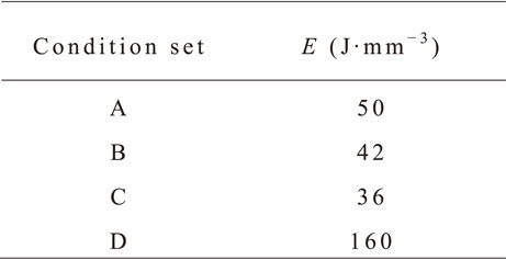
Table 2 Calculated energy density.
As-prepared samples were heat treated at 650°C for 3 h to remove residual thermal stresses and were then air-cooled. The stress-relief treatment conditions were adapted from Ref. 19). To investigate the microstructural changes induced by heat treatment, the samples were heat treated at 950°C for 2 h in the α + β phase field and then water-quenched. Because the SLM samples often contain pores, hot isostatic pressing (HIP) was applied to remove pores.20) The HIP treatment for the as-prepared samples was carried out at 954°C and 103 MPa for 2 h under an Ar gas atmosphere, and the samples were cooled in the furnace. The samples heat treated at 650°C are referred to as stress-relief-treated samples. The samples heat treated at 950°C after the stress-relief treatment are referred to as heat-treated samples. The samples subjected to HIP are referred to as HIP-treated samples.
To measure the porosities introduced by the SLM process, ϕ1 × 10 mm2 samples were cut from as-prepared, stress-relief-treated, heat-treated, and HIP-treated samples using an electric discharge machine. The porosities were measured using an X-ray computed tomography (X-ray CT) system (SMX-160CT-SV3, Shimadzu). The three-dimensional data were reconstructed using analysis software (VG Studio, Volume Graphics), and the volume fraction of porosities was measured.
Forged samples were also prepared for comparison with the SLM samples. A 1.1 kg ingot of Ti–6Al–4Nb–4Zr was melted using a cold-crucible levitation melting method. The ingots were forged and groove-rolled at 900°C in the α + β two-phase field to form a square rod 14.3 mm in size. The heat-treatment temperature was maintained at 950°C for 3 h in the α + β two-phase field, followed by air cooling.
The microstructures of the as-prepared, stress-relief-treated, heat-treated, HIP-treated, and forged samples were observed by field-emission scanning electron microscopy (FE-SEM, JOEL JSM-7200F) in conjunction with electron backscatter diffraction (EBSD) and energy-dispersive X-ray spectrometry (EDS) using an acceleration voltage of 20 kV. Specimens for microstructure observation were embedded in resins and polished using polishing paper, diamond pastes with particle sizes of 9, 6, and 1 µm, and SiO2 as the final polishing.
To investigate the mechanical properties, compression tests were carried for the as-prepared, stress-relief-treated, heat-treated, HIP-treated, and forged samples using a universal testing machine (AG-X, Shimadzu). The strain rate was 3.0 × 10⁻⁴ s−1, and the temperature was varied from room temperature to 600°C. Samples with dimensions of 2.5 × 2.5 × 5.5 mm3 were prepared for the compression tests. Tensile creep tests were conducted at 600°C and under a loading stress of 137 MPa in air for the samples heat treated after the stress-relief treatment, the HIP-treated samples, and the forged samples until fracture occurred. The elongation was measured using a linear gage, and the testing temperature was measured using R-type thermocouples attached to the specimens. The gage diameter and gage length of the creep specimens were 3 and 13.5 mm, respectively. The gage diameter and gage lengths of the forged samples were 6 and 30 mm, respectively.
3. Results and Discussion
3.1 Microstructure
3.1.1 Microstructure of SLM samples
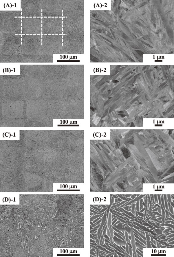
Backscattered-electron images of the horizontal and vertical cross-sections relative to the build direction of the as-prepared samples are shown in Figs. 1 and 2, respectively. Scale-like patterns of the prior-β grains were observed in the low-magnification images of the samples fabricated under condition sets A, B, and C (Figs. 1(A)-1, (B)-1, and (C)-1). The size of these scale-like patterns was approximately 100 µm, consistent with the hatch spacing. The scale-like patterns are well known to correspond to the shape of the melting pool formed under continuous laser irradiation of each layer.21) In the corresponding high-magnification images (Figs. 1(A)-2, (B)-2, and (C)-2), a martensitic structure, which often forms during rapid cooling, is observed. However, no scale-like patterns were observed in the specimen fabricated under condition set D, and the prior-β grain size was approximately 300 µm (Fig. 1(D)-1). The lamellar structure consisting of a thick α phase (dark phase) and thin β phase (bright phase) was observed inside grains because of the low cooling rate (Fig. 1(D)-2).
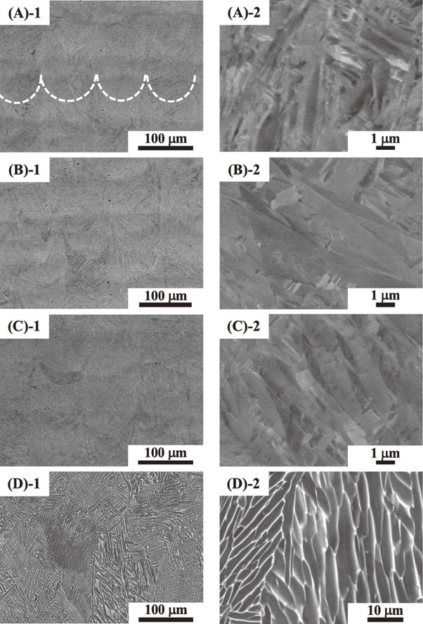
In the microstructures of the cross sections vertical to the build direction, the lattice-like prior-β grains indicated by white dotted lines were observed instead of the scale-like patterns, as shown in Figs. 2(A)-1, (B)-1, and (C)-1. The width of this lattice was approximately 100 µm, corresponding to the laser hatch spacing. These observations also indicate the macroscopic microstructure corresponding to the irradiation pattern. Under condition set D, no lattice microstructure was observed. We considered that the smaller hatch spacing led to the low cooling rate because of overlap of the melting area. The shape of the melting pool then disappeared, and the β grains grew to 300 µm.
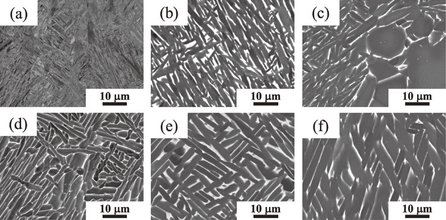
The effects of the heat treatment and the HIP treatment on the microstructure were investigated for samples fabricated under condition sets B and D because these samples were prepared using equal laser scanning speeds but the laser power was higher and the hatch spacing was smaller under condition set D. The microstructures of the stress-relief-treated specimens, the specimens heat treated at 950°C after the stress-relief treatment, and the HIP-treated specimens are shown in Fig. 3. Compared with the microstructures of the as-prepared samples (Figs. 1(A)-2 and 1(D)-2), those of the stress-relief-treated samples prepared under condition sets B and D did not exhibit drastic changes, as shown in Figs. 3(a) and (d). Further heat treatment at 950°C for 2 h followed by water quenching substantially changed the microstructure of the sample prepared under condition set B (Fig. 3(b)). The martensitic structure disappeared, and the α and β phases coarsened to a plate-like morphology and finally became a Widmanstätten structure. The microstructures near the scale-like patterns are shown in Fig. 4. The equiaxed α phase approximately 10 µm in size formed along the boundaries of the scale-like patterns. For the sample prepared under condition set D, the microstructure did not substantially change after the stress-relief treatment or the heat treatment; however, the thickness of the α and β phases slightly coarsened after the heat treatment at 950°C, as shown in Fig. 3(e). The phase composition was measured using EDS; however, compared with the phase composition of the as-prepared sample, no clear difference was observed after the stress-relief treatment or heat treatment. After the HIP treatment of the sample prepared under condition set B, an equiaxed α phase with a size of ∼10 µm or larger formed in the Widmanstätten structure, as shown in Fig. 3(c). However, no equiaxed α phase formed and coarsening of the α phase was not observed after HIP treatment of the sample prepared under condition set D (Fig. 3(f)).
The formation of the equiaxed α phase is explained by the α phase tending to nucleate preferentially at high angle boundaries greater than 15°, which have a higher interface energy.21,22) The boundaries of the scale-like patterns correspond to the boundaries of the prior-β grains with a high angle; the equiaxed α phase formed preferentially at the boundaries of the scale-like patterns.21) If the equiaxed α phase preferentially forms at the boundaries with a high angle, it should form in the sample fabricated under condition D because the crystal orientation of the solidified β grains is random and the β grains develop high angle boundaries.
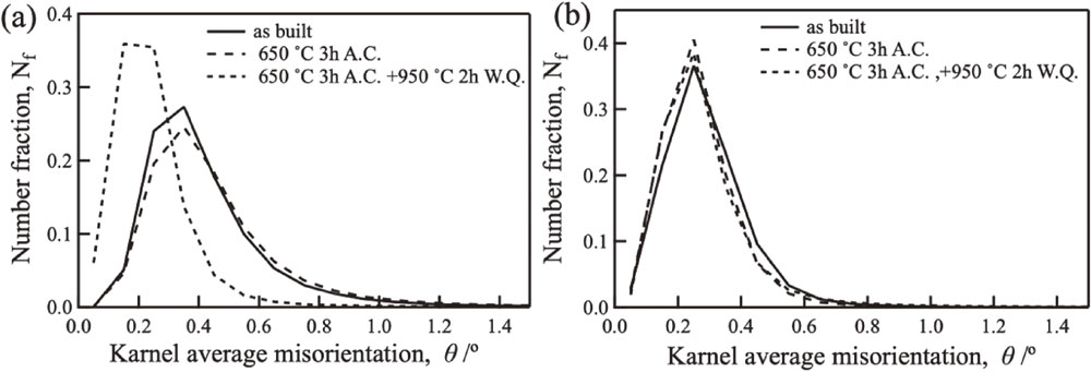
The formation of the equiaxed α phase is also explained by the stress induced during SLM producing strain inside the samples, leading to nucleation of the equiaxed α phase. Severe deformation is well known to be necessary for forming the equiaxed α and β phases in forging materials because the induced strain induces recrystallization of the α and β phases.5) The residual strains of the as-prepared, stress-relief-treated, and heat-treated samples were subsequently investigated using EBSD. Figure 5 shows the distribution of the kernel average misorientation (KAM), which represents the residual strain. For the samples prepared under condition B, the distribution of the KAM in the as-prepared and stress-relief-treated specimens was overlapped; by contrast, the distribution of the KAM in the heat-treated specimen shifted to lower misorientation angles compared with those in the as-prepared and stress-relief-treated specimens. These results indicate that the residual strain induced by SLM remained after the stress-relief treatment and was removed after the heat treatment at 950°C. However, the strain distribution was not changed by the heat treatment of the sample prepared under condition set D. The formation of the equiaxed α phase in the samples fabricated under condition set B was therefore caused by the residual strain induced during SLM, and the residual strain was released during the heat treatment at 950°C.
The equiaxed α phase formed in the sample prepared under condition set B and subjected to the HIP treatment (Fig. 3(c)). Because the as-prepared sample was directly HIP treated at 954°C, which is similar to the heat-treatment temperature (950°C), the strain induced during SLM caused nucleation of the equiaxed α phase.
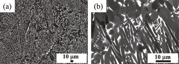
3.1.2 Microstructure of a forged sample
For comparison with the microstructure of the SLM samples, the microstructure of the forged sample was also observed. A typical bimodal structure consisting of the equiaxed α phase and the α/β lamellar structure in the equiaxed grains was observed after the heat treatment at 950°C for 3 h followed by air cooling (Fig. 6(a)). The grain size was approximately 10 µm, and the area fraction of the equiaxed α phase (Sα) was 45%. The grain size was smaller in the forged sample than in the SLM samples. The volume fraction of the equiaxed α phase was governed by the equilibrium fraction at the heat-treatment temperature. However, the prior-β grain size was governed by the process of solidification from the melting pool, which was controlled by the processing conditions for the SLM samples. When the heat-treatment temperature was increased to 980°C, the grains grew drastically to approximately 800 µm (Fig. 6(b)) and the fine α/β lamellar structure was formed inside the grains. This change in the microstructure indicates that the β-transus temperature is between 950 and 980°C.

Pores are known to be created during SLM because of insufficient melting when the energy density from laser irradiation is low or when ambient gas is entrained when the energy density is excessive and the flow of the molten pool becomes more active.23,24) Because pores affect the specimens’ mechanical properties, we used X-ray CT to test the porosity of samples prepared under condition sets B and D. The volume fractions of pores detected by X-ray CT are reported in Table 3. The porosities of the as-prepared samples were 0.1–0.2%. In the case of the sample prepared under condition set D, the porosity was reduced by the stress-relief treatment and by the heat treatment. However, the effect of the 950°C heat treatment on the sample prepared under condition set B was unclear. We speculate that the volume fraction of pores varied depending on the location of the measurement. The results for the sample prepared under condition set D suggests that heat treatment tends to reduce porosity. In addition, the HIP treatment was clearly effective in eliminating pores in samples prepared under condition sets B and D. No pores were observed in the forged samples (data not shown in Table 3).
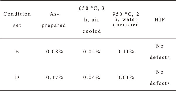
Table 3 Volume fraction of pores induced during SLM.
The 0.2% proof stress of the SLM samples is shown in Fig. 7. The samples fabricated under condition set C, which included the highest cooling rate among the investigated sets of conditions, exhibited higher stress than the samples prepared under the other condition sets. The 0.2% proof stress decreased with decreasing cooling rate from condition set C to condition set A, and the strength of the sample prepared under condition set D was the lowest among the investigated SLM samples. Two factors explain the observed difference in strength. First, the decrease in the 100 µm grain size of the samples prepared under condition sets A, B, and C indicates greater strength compared with that of the sample prepared under condition set D, which exhibited a grain size of 300 µm. Second, the microstructure of the samples prepared under condition sets A, B, and C is finer than that of the sample prepared under condition set D. In the samples prepared under condition sets A, B, and C, the martensitic structure and the interface of the martensite α phase obstruct the dislocation motion. In general, a finer microstructure tends to obstruct dislocation motion. However, in the sample fabricated under condition set D, a lamellar structure was formed and the effect of dislocation motion obstruction in the coarse structure was reduced.
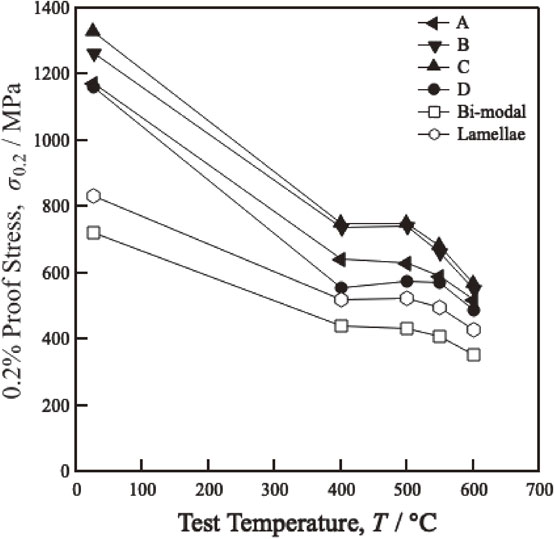
The strengths of the forged samples with bimodal and lamellar structures are shown in Fig. 7. The strengths of the forged samples were lower than those of the as-prepared SLM samples. A comparison of the lamellar structure in the forged sample with that in the sample prepared by SLM under condition set D reveals the effect of the grain size on the strength. The grain sizes of the sample prepared under condition set D and that in the forged sample are approximately 300 and 500 µm, respectively. A smaller grain size is associated with higher strength. The bimodal structure, despite its smaller grain size of 10 µm, exhibits the lowest strength among the tested samples. Al, the solid-solution strengthening element of the α phase, partitions in the equiaxed α phase during heat treatment in the α + β two-phase region.5) As a result, the α phase in the lamellar structure formed from the β phase during cooling lacked sufficient solid-solution strengthening element (i.e., Al) and the strength of its lamellar structure was therefore lower than those of the other samples. To design high-temperature α + β Ti alloys, the volume fraction of the equiaxed α phase should be reduced as much as possible.5,25) In the bimodal structure, the area fraction of the equiaxed α phase was 45% and the solid-solution strengthening element Al was considered to not be partitioned in the α phase in the lamellar structure, resulting in the sample with a bimodal structure exhibiting the lowest strength among the tested samples.
We next investigated the effect of the heat treatment on the 0.2% proof stress of samples prepared under condition sets B and D. The results are presented in Fig. 8, together with the strength of the forged sample with a lamellar structure. For the sample prepared under condition set B (Fig. 8(a)), the strengths of the as-prepared and the stress-relief-treated samples were the highest and were approximately the same within the investigated range of test temperatures. However, the 0.2% proof stress decreased after the heat treatment at 950°C for 2 h because the microstructure changed from martensitic to a Widmanstätten structure and the number of obstacles impeding dislocation motion decreased. In addition to this microstructure change, the equiaxed α phase with a 10 µm particle size formed during the heat treatment. As observed for the bimodal structure, the formation of the equiaxed α phase lowers the strength because of insufficient Al partitioning into the lamellar structure. The 0.2% proof stress decreased substantially in the HIP-treated specimens. In the HIP-treated specimens, a large equiaxed α phase with a particle size greater than 10 µm was formed. This large equiaxed α phase prohibited partitioning of Al into the lamellar structure, resulting in lower strength compared with that of the other SLM samples. By contrast, for the sample prepared under condition set D, the effect of the heat treatment on the strength was small (Fig. 8(b)) because the equiaxed α phase did not form upon heat treatment or HIP treatment and because the microstructure change was sufficiently small, although slight coarsening of the α phase was observed.
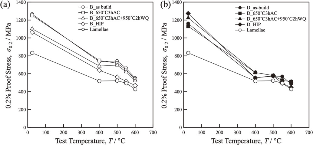
The strengths of the lamellar structure in the forged samples were lower than those of the heat-treated or HIP-treated samples. As shown in Fig. 7, this effect is attributable to the large grain size of the forged sample.
3.4 Creep properties
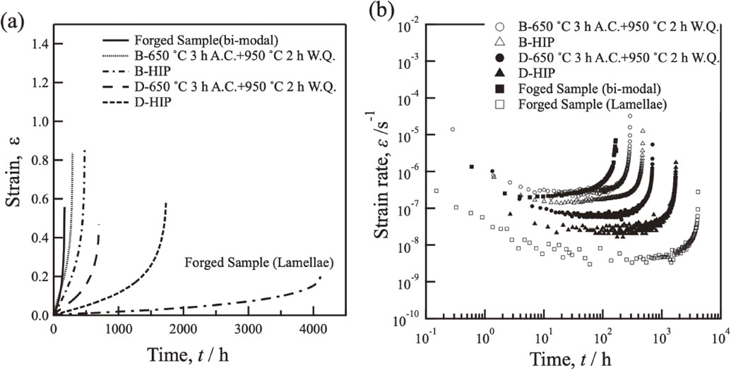
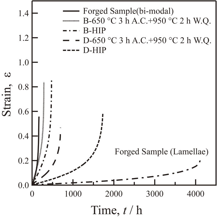
Unlike the mechanical properties at room temperature, those at high temperatures involve diffusion, which causes time-dependent deformation (creep deformation) even at stresses below the yield stress. Creep tests were conducted at a test temperature of 600°C under a loading stress of 137 MPa. The creep tests were performed on specimens heat treated at 950°C for 2 h after the stress-relief treatment of samples prepared under SLM condition sets B and D, and on HIP-treated specimens. For comparison, the creep test was performed on the forged specimen with a bimodal structure. The time–strain and time–strain rate curves obtained from the creep tests are shown in Fig. 9. The creep rupture time and the minimum creep rate obtained from Fig. 9 are summarized in Table 4.
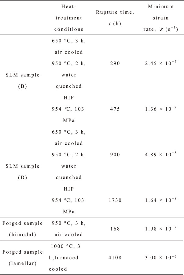
Table 4 Rupture time and minimum strain rate of SLM and forged samples.
The results in Fig. 9 and Table 4 show that the rupture lifetimes of the SLM samples, which ranged from 120 h to more than 1500 h, were longer than that of the forged sample with a bimodal structure. The rupture life increased with increasing grain size from 10 µm in the bimodal structure to 100 and 300 µm in the SLM samples fabricated under condition sets B and D, respectively. The minimum creep rate was on the order of 10−7 s−1 for the sample prepared under condition set B and 10−8 s−1 for that prepared under condition set D. For reference, the creep curve of the lamellar structure in the forged sample with a grain size of 800 µm after heat treatment at 1010°C for 3 h followed by furnace cooling is also shown in Fig. 9(a).26) The creep rupture life was longer than 4000 h, and the creep strain rate was 10−9 s−1 (Table 4). The results indicate that the creep life of samples tested at 600°C and under a loading stress of 137 MPa depends on the grain size.
The creep deformation mechanism of materials is known to depend on the deformation temperature, applied stress, and grain size.27,28) In a previous study, we found the creep deformation mechanism at 600°C to change from grain boundary sliding in conjunction with dislocation slip at an applied stress less than 200 MPa to dislocation slip when the applied stress was greater than 200 MPa for Ti-alloy samples with a grain size between 100 and 500 µm.29) According to a previous study, grain boundary sliding is the dominant deformation mechanism and dislocation slip also occurs under the present creep conditions of 600°C and 137 MPa. The creep strain rate is proportional to d−2, where d is the grain size.30,31) Thus, when the grain size is small, the creep strain rate drastically increases. In the present study, the grain size of the forged material was 10 µm, which is smaller than those of the other investigated samples, resulting in a shorter fracture life of the forged samples. However, for the samples prepared under SLM condition sets B and D, where the grain size is 100 and 300 µm, respectively, the effect of the grain boundary sliding was reduced. The longer observed creep life of the sample fabricated under condition set D compared with those of the sample with a bimodal structure and the SLM sample prepared under condition set B is reasonable. In the sample prepared under condition set B, the formation of the equiaxed α phase obstructs Al partitioning in the α phase of the lamellar structure. As reflected in the results of the compressive strength measurements, insufficient Al partitioning in the α phase of the lamellar structure is also why the sample prepared under condition set B exhibited a shorter creep life than the sample prepared under condition set D. The HIP-treated specimens exhibited longer creep lifetimes than the heat-treated specimens of the samples prepared under conditions B and D. The X-ray CT results summarized in Table 3 indicate that pores were eliminated by the HIP treatment. Eliminating internal pores in the specimens contributed greatly to the substantial increase in their rupture life and decrease in their minimum creep rate.
The size of grains formed during forging and heat treatment is determined by the heat-treatment temperature. When the sample is heat treated in the α + β two-phase region, the grain size is approximately 10 to 100 µm; however, when the sample is heat treated in the β-phase region, the grains rapidly grow larger than 500 µm. Generating grains with a moderate size between 100 and 500 µm by forging is difficult. However, in SLM, the grain size is related to the size of the melting pool and can be controlled via the processing conditions. As a result, moderate-sized grains can be obtained. Both good fatigue properties and good creep properties are required for high-temperature Ti alloys used in jet engine applications. In general, alloys with a small grain size exhibit good fatigue properties. Thus, SLM has the potential to produce a suitable microstructure with a medium grain size, resulting in a balance of favorable creep and fatigue properties.
4. Conclusions
The evolution of the microstructure in Ti–6Al–4Nb–4Zr (mass%), an α-stabilized alloy similar to Ti–6Al–4V, prepared under various SLM processing conditions and after various heat treatments was investigated, along with the mechanical properties of the samples.
-
(1)
A scale-like structure related to the melting pool formed by rapid cooling. Inside the scale-like structure, a martensitic structure formed, whereas a scale-like structure was not obtained and the α/β lamellar structure was formed via slow cooling during SLM.
-
(2)
The as-formed microstructure did not change at the macroscopic level after the stress-relief treatment.
-
(3)
The martensitic structure changed to a Widmanstätten structure after the heat treatment at 950°C for 2 h, followed by water quenching. The equiaxed α phase was also formed at the scale-like interface. The lamellar structure formed during slow cooling did not change after the heat treatment.
-
(4)
A higher compressive strength was obtained as the cooling rate was increased. The strength of the as-prepared samples and heat-treated samples prepared by SLM were greater than those of forged samples with a bimodal structure or lamellar structure at the investigated test temperatures. The compressive strength was governed by the fineness of the microstructure. The microstructures of the SLM samples were finer than those of the forged samples.
-
(5)
Creep life at 600°C and 137 MPa, where grain boundary sliding occurs according to previously reported research, depended on the grain size (i.e., the melting pool size in SLM). SLM induced a small amount of pores, which were eliminated by HIP. The creep life of the HIP-treated samples was longer than that of samples not subjected to the HIP treatment, indicating the importance of eliminating the micropores to achieve suitable creep properties.
Acknowledgments
Part of this work was supported by Grants-in-Aid for Transformative Research Area A, 21H05198 and The Light Metal Educational Foundation. The authors thank Mr. S. Iwasaki, Mr. K. Iida, and Mr. M. Kobayashi at NIMS for preparing an ingot and a forged sample of Ti–6Al–4Nb–4Zr. The authors thank Ms. A. Takenouchi at NIMS for the CT-X-ray analysis measurement.
REFERENCES
- 1) P. Chandramohan, S. Bhero, K. Manikandasubramanian and B. Ravishankar: J. Eng. Sci. Technol. 3 (2018) 790–812.
- 2) Ó. Teixeira, F.J. Silva, L.P. Ferreira and E. Atzeni: Metals 10 (2020) 1006. doi:10.3390/met10081006
- 3) P. Li, D.H. Warner, A. Fatemi and N. Phan: Int. J. Fatigue 85 (2016) 130–143. doi:10.1016/j.ijfatigue.2015.12.003
- 4) C. Leyens and M. Peters: Titanium and Titanium Alloys - Fundamentals and Applications, (Wiley-VCH, Weinheim, 2003).
- 5) G. Lütjeing and J.C. Williams: Titanium, 2nd ed., (Springer-Verlag, Berlin, 2007).
- 6) T.D. Ngo, A. Kashani, G. Imbalzano, K.T.Q. Nguyen and D. Hui: Compos., Part B 143 (2018) 172–196. doi:10.1016/j.compositesb.2018.02.012
- 7) S. Liu and Y.C. Shin: Mater. Des. 164 (2019) 107552. doi:10.1016/j.matdes.2018.107552
- 8) A. Cardon, C. Mareau, Y. Ayed, S. Van Der Veen and P.D. Santo: AIP Conference Proceedings 1, 2113, (AIP Publishing, 2019) p. 150018.
- 9) L.M. Viespoli, S. Bressan, T. Itoh, N. Hiyoshi, K.G. Prashanth and F. Berto: Eng. Fail. Anal. 111 (2020) 104477. doi:10.1016/j.engfailanal.2020.104477
- 10) S. Spigarelli, C. Paoletti, M. Cabibbo, E. Cerri and E. Santecchia: Addit. Manuf. 49 (2022) 102520. doi:10.1016/j.addma.2021.102520
- 11) Y.K. Kim, S.H. Park, J.H. Yu, B. AlMangour and K.A. Lee: Mater. Sci. Eng. A 715 (2018) 33–40. doi:10.1016/j.msea.2017.12.085
- 12) S. Matsunaga, A. Serizawa and Y. Yamabe-Mitarai: Mater. Trans. 57 (2016) 1902–1907. doi:10.2320/matertrans.MAW201603
- 13) Y. Yamabe-Mitarai, R. Zempo, T. Kitashima, S. Emura and H. Murakami: Proc. of the 1st International Conf. on 123HiMAT-2015, (2016) pp. 335–338.
- 14) Y. Yamabe-Mitarai, A. Jastrzebska, T. Kitashima, S. Emura, H. Murakami, R. Zempo and Z. Pakiela: Proc. of the 13th World Conference on Ti, (TMS, 2016) pp. 917–921.
- 15) K. Shimagami, A. Yumoto, T. Ito and Y. Yamabe-Mitarai: Mater. Trans. 58 (2017) 1404–1410. doi:10.2320/matertrans.MAW201707
- 16) K. Shimagami, T. Ito, Y. Toda, A. Yumoto and Y. Yamabe-Mitarai: Mater. Sci. Eng. A 756 (2019) 46–53. doi:10.1016/j.msea.2019.04.031
- 17) H. Attar, S. Ehtemam-Haghighi, D. Kent, X. Wu and M.S. Dargusch: Mater. Sci. Eng. A 705 (2017) 385–393. doi:10.1016/j.msea.2017.08.103
- 18) J. Kluczyński, L. Śnieżek, K. Grzelak and J. Mierzyński: Materials 11 (2018) 2304. doi:10.3390/ma11112304
- 19) Y. Sakurai and K. Kakehi: J. Jpn. Inst. Met. Mater. 81 (2017) 120–126. doi:10.2320/jinstmet.J2016042
- 20) B. Vayssette, N. Saintier, C. Brugger and M. El May: Theor. Appl. Fract. Mech. 108 (2020) 102581. doi:10.1016/j.tafmec.2020.102581
- 21) S. Miyazaki, M. Kusano, D.S. Bulgarevich, S. Kishimoto, A. Yumoto and M. Watanabe: Mater. Trans. 60 (2019) 561–568. doi:10.2320/matertrans.MBW201806
- 22) S.M.C. van Bohemen, A. Kamp, R. Petrov, L.A.I. Kestens and J. Sietsma: Acta Mater. 56 (2008) 5907–5914. doi:10.1016/j.actamat.2008.08.016
- 23) H. Gong: Mater. Des. 86 (2015) 545–554. doi:10.1016/j.matdes.2015.07.147
- 24) J. Kluczyński, L. Śnieżek, K. Grzelak and J. Mierzyński: Materials 11 (2018) 2304. doi:10.3390/ma11112304
- 25) H. Mishra, P. Ghosal, T.K. Nandy and P.K. Sagar: Mater. Sci. Eng. A 399 (2005) 222–231. doi:10.1016/j.msea.2005.03.027
- 26) K. Shimagami: Master thesis in Shibaura Institute of Technology (2018).
- 27) J. Weertman: Trans. Am. Soc. Met. 61 (1968) 681–694.
- 28) H.J. Frost and M.F. Ashby: Deformation Mechanism Maps, (Pergamon Press, Oxford, 1982) pp. 43–51.
- 29) H. Masuyama, T. Matsunaga, Y. Toda, T. Ito, M. Shimojo and Y. Yamabe-Mitara: Mater. Sci. Forum 1016 (2021) 1882–1889. doi:10.4028/www.scientific.net/MSF.1016.1882
- 30) H. Lüthy, R.A. White and O.D. Sherby: Mater. Sci. Eng. 39 (1979) 211–216. doi:10.1016/0025-5416(79)90060-0
- 31) O.D. Sherby and J. Wadsworth: Prog. Mater. Sci. 33 (1989) 169–221. doi:10.1016/0079-6425(89)90004-2