1. Introduction
Because metal materials with smaller grains generally have better mechanical properties,1) a grain refinement method for these materials, particularly the casting of grains that grow coarsely during solidification, has long been needed. So far, a few methods of grain refinement by casting have been studied, such as soaking the oscillator in molten metal,2) electromagnetic stirring,3) electromagnetic vibration,4) ultrasonic vibration,5–11) and casting from a lower temperature.12)
In our previous study, to refine the grains of the cast metal, we investigated the creation of Al–Cu and Al–Si alloys using a “vibration mold” that could vibrate the molten metal. The results showed that the primary α phase of the hypoeutectic Al–Cu alloy and primary Si phase of the hypereutectic Al–Si alloy could be refined.13,14) Because of this, it was reasoned that many crystal nuclei are generated on the mold wall and upper surface of the molten metal by vibration and are then continuously transported into the molten metal by convection.
Some methods utilizing water and solutions have been used to directly observe the crystallization and convection of molten metal during solidification, for example, putting nylon thread in water or glycerin solution,15) putting pieces of aluminum foil in water,16) and using ammonium chloride solution (H2O–NH4Cl).17–20) The methods using nylon thread and aluminum foil in water are limited to only observing convection. However, using an ammonium chloride solution, the generation and growth of crystals can also be observed. Therefore, a method called “water model experiment” using ammonium chloride solution was performed in this study to confirm the mechanism of grain refinement using the vibration mold.
In addition, based on the findings obtained from the water model experiment, the grain refinement mechanism of the cast metal was investigated by conducting a practical experiment with Al–2%Cu alloy using the same mold shape as the water model experiment.
2. Experimental Methods
2.1 Water model experiment
The casting material used in the water model experiment was 37% ammonium chloride solution, which is relatively easy to heat and observe the crystallization of. If the concentration of ammonium chloride is greater than 19%, ammonium chloride crystallizes as the primary phase, as shown in Fig. 1. The amount of solution used was 80 or 150 ml depending on the shape of the mold. The ammonium chloride solution was heated from 363 to 373 K and poured into the mold set on the vibration device shown in Fig. 2, which was at 363 K.
Figures 3(a) to (d) show schematic representations of the various molds made of aluminum blocks of 20 mm thickness. They have transparent polycarbonate windows to allow the observation of the solidification behavior.

Figure 3(a) shows a mold with the top surface open to atmosphere (open mold), similar to those used in previous studies.13,14) The molds (b), (c) and (d) include a riser on the top to investigate its effect. (b) is a full plugged mold in which the specimen section was separated from the riser using a rubber plug immediately after casting to suppress wave generation in the specimen section. (c) is a full plugged mold with stirring in which a stirrer was placed in the specimen section after casting, the rubber plug was set and then the stirrer was spun to cause convection in the solution. (d) is a mold with weir made of rubber, which was set on the bottom of the riser to prevent the crystals generated in the riser from settling down to the specimen section. In addition, the molds (b), (c), and (d) have a slope at the top of the specimen section to prevent bubbles from remaining inside the mold after casting.
When the open mold (a) and the mold with weir (d) were used, vibration was started before casting and continued until the solution temperature dropped to room temperature to ensure that the ammonium chloride solution solidified completely. For the full plugged mold (b), the specimen section was plugged just after casting, after which vibration was started. For the full plugged mold with stirring (c), the specimen section was plugged just after casting, after which the stirrer was spun to cause convection in the solution. For the molds (a), (b), and (d), the vibration conditions were a half-amplitude of 0.6 mm and a frequency of 20 or 30 Hz. When the full plugged mold with stirring (c) was used, vibration was not applied.
2.2 Demonstration of the vibration mold using Al–2%Cu alloy
Hypoeutectic Al–2%Cu alloy was used in the practical experiment. Raw material (1.3 kg) was melted in a graphite crucible using an electric furnace, after which it was poured into the vibration mold at 1023 K. Vibration was started before pouring and stopped after the molten metal had solidified completely. The vibration conditions were 1 mm half-amplitude and 15 Hz frequency.
Figure 4 shows the schematic illustration of the metal mold with a weir used in the demonstration. The interior of the cast-iron mold measures 50 × 50 × 65 mm and that of the riser φ75 × 65 mm. Its size is the same as that of the mold (Fig. 3(d)) used for the water model experiment, except for a deeper specimen section (25 mm) and a thicker riser, meaning solidification is slightly delayed. The inside wall of the mold was coated with boron nitride and the temperature of the mold was set at room temperature. Furthermore, refractory bricks were used for the weir and constricted section in the center of the mold to prevent the specimen from solidifying due to the constriction. The thickness and length of the weir are slightly smaller than those of the mold in the water model because the refractory bricks break easily. After testing, the specimens were cut along the direction of vibration and their macrostructures were observed using optical microscopy.
3. Experimental Results and Discussion
3.1 Water model experiment
3.1.1 The effect of mold vibration on crystal growth in the open mold
Figure 5 shows the changes in appearance of the solution in the open mold (Fig. 3(a)) as vibration time increases. Without vibration, crystal formation was not observed immediately after casting. After approximately 2 s, however, ammonium chloride crystals formed and grew toward the center of the mold over time. At 2 min after casting, the crystals had grown 10 mm from the mold wall and were also growing from the solution surface toward the bottom of the mold. Solidification finished completely at 5 min after casting. The circular spots observed on the polycarbonate plate are air bubbles.

On the other hand, when vibration was applied (half-amplitude: 0.6 mm, frequency: 20 Hz), high waves were generated in the solution, with crystals forming near the boundary between the mold wall and the solution surface immediately after casting. After 5 s, crystals had formed from the entirety of the mold wall, with the number of crystals increasing rapidly. In addition, the crystals were dispersed into the solution by convection. After 20 s, the inside of the mold was filled with a large number of crystals.
As mentioned, waves were generated on the solution surface and a large number of crystals formed near the boundary between the mold wall and the solution surface when vibration was applied to the mold, with the number of crystals increasing with an increase in the frequency and half-amplitude. These results indicate that there are significant differences in the formation and growth of crystals in the open mold with and without vibration.
3.1.2 Effect of waves and convection by vibration on crystal growth
In the previous section, it was found that waves on the solution surface and convection inside the mold occurred during vibration. Therefore, as shown in Fig. 3(b), the specimen section was completely sealed by a plug to prevent the formation of waves on the solution surface. Using this, the effect of waves on crystal growth was investigated.
Figure 6 shows the changes in crystal growth associated with vibration in sealed and unsealed molds. Without vibration, ammonium chloride crystals formed at the mold wall of both the specimen section and the riser, gradually growing toward the center of the mold similar to the results of the open mold. When vibration was applied to the unsealed mold, the generated crystals filled the entire mold in approximately 1 min. At this time, most of the crystals were observed near the boundary between the mold wall and the solution surface, falling along the mold wall of the riser and moving to the specimen section. This behavior is the same as that observed in the open mold described in 3.1.1.

Conversely, when vibration was applied to the mold sealed with a plug, many crystals formed near the boundary between the mold wall of the riser and the solution surface immediately after pouring, with a large number of crystals occupying the bottom of riser and the mold wall after 10 s. After 1 min, the crystals had filled the entire riser section. For the specimen section, waves and convection were not observed, with crystals only gradually growing from the mold wall toward the center of the section without vibration. Even after 1 min, there was not much difference in the crystal growth behavior with or without vibration.
These results demonstrate that if there are no waves on the solution, the rapid formation of crystals is prevented even if vibration is applied. Therefore, it can be said that the generation of waves and convection by vibration are required for grain refinement.
3.1.3 Effect of convection on crystal growth
As mentioned in 3.1.1 and 3.1.2, the experimental results using the open and unsealed molds with vibration indicate that waves on the surface of the solution and convection in it occur simultaneously when vibration is applied, greatly affecting crystal formation. Therefore, to clearly distinguish the effect of convection on the generation of crystals from that of the waves on the solution surface, convection alone was generated inside the solution by a stirrer in the full plugged mold with stirring (Fig. 3(c)).
Figure 7 shows the changes in appearance of the full plugged mold with stirring over time. The speed of the stirrer was set to be similar to the convection speed observed in the solution during the experiment using the open mold. Over time, some crystals were generated on the wall of the specimen section, growing toward the center of the mold, with few crystals seen in the remaining solution although some were picked up by the convection from the stirring. This result is similar to that of the specimen section of the full plugged mold (0.6 mm, 30 Hz), in which waves and convection were not produced (Fig. 6). This indicates that convection is not the main cause of crystal generation. The main effect of convection is to bring the crystals formed near the mold wall into the solution of the specimen section.
3.1.4 Effect of a weir on crystal growth
As described above, it is clear that a large number of crystals are generated near the boundary between the mold wall and the solution surface when the mold is vibrated, with convection contributing to the transportation of generated crystals into the specimen section. Therefore, to prevent crystals generated near the boundary between the riser wall and the solution surface from being transported into the specimen section, an experiment was performed using a mold with a rubber weir set into the riser (Fig. 3(d)).
Figure 8 shows the changes in appearance in the mold with a weir over time. With vibration, many crystals were sequentially generated near the boundary between the solution surface and the wall of the riser immediately after pouring. After 1 min, however, the weir had prevented the crystals from moving from the riser to the specimen section. Additionally, although the waves were primarily only generated near the center of the solution surface (the circle in the figure), the generation of crystals was still observed. Furthermore, there were few crystals in the solution in the specimen section, with crystal growth only occurring from the mold wall to the center of specimen section. From these results, it is clear that the site at which the majority of the crystals are generated is the boundary between the solution surface and the mold wall. There was little convection from the mold wall to the specimen section, and transportation of the crystals between them was not observed.

It has been established that waves are produced at the boundary between the solution surface and the mold wall and are necessary for the plentiful generation of crystals. The amplitude and wave length of the solution surface would vary depending on the vibration conditions. Therefore, the relationship between the vibration conditions, particularly the wave height at the mold wall, and crystallization, was investigated.
Figure 9 shows the relationship between the excitation force and the wave height (Height = Hmax − Hmin) of the ammonium chloride solution in the open mold. As the excitation force increases, the wave height also increases, reaching approximately 10.5 mm at 0.8 N. After that, the wave height only increases gradually, reaching approximately 15 mm at 5 N.

Figure 10 shows the relationship between the wave height in this experiment, the average grain size of the Al–2%Cu alloy in the previous study,13) and the excitation force. Because the ammonium chloride solution in the water model and the Al–2%Cu alloy have a different viscosity and mass, the excitation force is different. However, as the excitation force increases, the average grain size decreases significantly, reaching a constant value. Conversely, the wave height greatly increases with an increase in the excitation force, also attaining a constant value. It is assumed that the wave in the Al–2%Cu alloy also becomes higher as the excitation force increases. It can thus be presumed that there is a correlation between the wave height and the average grain size of the Al–2%Cu alloy. According to previous studies for the hypereutectic Al–Si alloy, when vibration was applied, the grains of primary Si became finer as the excitation force was increased, with the grains of the alloy structure also becoming finer as a whole.14,21) Based on the above experimental results using the water model, the mechanism of grain refinement in cast metal using a vibration mold is described as follows. When vibration is applied, waves generate in the molten metal. The higher the frequency and amplitude of the vibration, the higher the wave height. Thus, as the vibration becomes longer, the contact area with the mold wall increases, also increasing the number of generated crystals. The crystals generated at the mold wall are swept into the mold by the pull of the waves and then migrates throughout the mold by convection. This process is then repeated. As a result, because a large number of crystals are generated, the crystal grains become finer.

Based on the results of the water model experiment, demonstrations using molds with and without a weir were conducted using Al–2%Cu alloy.
Figure 11 shows the macrostructure of each specimen generated with or without a weir and with or without vibration. Without vibration, the entire cross section of the specimen is occupied by columnar crystals regardless of whether the mold has a weir. By contrast, when vibration is applied to the mold without a weir, the columnar crystals grown from the casting wall are short, with most of the central region of the specimen occupied by equiaxed crystals. When a weir is present, fine grains are produced at the top and bottom of the specimen; however, long columnar crystals grow from the mold wall, almost reaching the center region of the mold. This indicates that the grain refinement due to vibration is greatly reduced by the weir. Furthermore, the finer grains at the bottom of the specimen are accumulated, which is attributed to the fact that the surface of the molten metal exists in the specimen section at the early stage after casting, so that the fine grains generated by the vibration are deposited at the bottom of the specimen.

Figure 12 shows the macrostructure of the risers of the specimens with vibration shown in Fig. 11. The columnar crystals grown from the mold wall are short, regardless of whether the mold has a weir, with the center region being occupied by fine equiaxed grains. When a weir is present, the lower part between the weir and the cast wall is occupied by columnar crystals, but the specimen in the vicinity of the upper part of the weir is filled with fine equiaxed crystals.
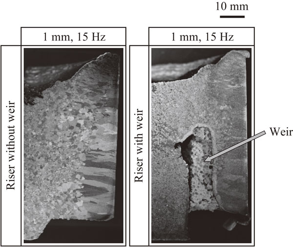
The fact that fine grains are not seen between the weir and the mold wall differs from the results of the water model experiment. According to a study by Momono et al.,20) the settling rate of aluminum is 6 times slower than that of crystal in ammonium chloride solution, assuming that Stokes’ law holds, and ammonium chloride solution has a lower thermal conductivity than that of the molten metal. From this, it is reasoned that in this experiment, α-phase crystals generated at the boundary between the surface of the molten metal and the mold wall slowly settle down, so that columnar crystals grow in the lower region and equiaxed grains grow in the upper region.
Considering the results of the water model experiments in 3.1.4 and 3.1.5 and those in this section, it is concluded that the grain refinement achieved by the vibration mold is attributed to the movement of the many grains generated between the surface of the molten metal and the wall of the mold into the inside of the molten metal by convection. This prevents the growth of columnar crystals from the wall of the mold.


