Materials Processing
Reduction of Surface Crack by Modified Molten Metal Pouring Method on Al–Mg Alloy Strips Produced by Twin-Roll Casting
2024 年 65 巻 1 号 p. 76-84
詳細
2024 年 65 巻 1 号 p. 76-84
In this study, cracks formed on the surface of Al–Mg alloy strips cast using a high-speed unequal-diameter twin-roll caster were observed. In addition, the effects of the roll load and the molten metal pouring method on the crack were investigated. Four types of Al–Mg alloys (AC7A, AC7B, Al–3%Mg, and Al–7%Mg) were cast into strips at roll speed of 30 m/min. The crack size decreased with decreasing roll load, and when the roll load was 4 N/mm, no cracks formed. However, the strips did not completely solidify under this low load, and conveyance was difficult due to the insufficient strength of as-cast strips. To reduce the load in the inner area along the width direction of the strips, the thickness of the solidification layer in this area was made shorter than that at the edges by modifying the molten metal pouring method. In the modified pouring method, the molten metal was poured onto the roll using a launder placed against the roll at a small angle. With this method, the edges completely solidified and had enough strength for conveyance. Moreover, cracking substantially improved, and when the distance between the edge of the molten metal pool and the pouring point was set, crack formation was almost completely eliminated. The band region at the center in the thickness direction of the strips was widened using the proposed pouring method. The tensile strength and limiting drawing ratio of strips cast using the proposed pouring method were both greater than those of the strips cast using the conventional pouring method.
This Paper was Originally Published in Japanese in J. JFS 94 (2022) 282–289. The main text in p. 82 was slighly modified.
The casting speed of a conventional twin roll caster for aluminum alloys (CTRCA) is slower than 2 m/min1) and high speed twin roll casters (HSTRCs), such as the vertical-type high speed twin roll caster (VHSTRC)2) and the unequal diameter twin roll caster (UDTRC),3) can cast at speeds from about 30 m/min up to 120 m/min.
The roll of the CTRCA is made from steel and parting material is sprayed on the roll. In contrast, the roll of the HSTRC is made from copper, which has a greater thermal conductivity than steel, and parting material, which adds heat resistance between the molten metal and the roll, is not used. As a result, the HSTRC can cast strip at higher speeds than the CTRCA. When Al–Mg strip is cast using the HSTRC, surface cracking occurs. The occurrence mechanism of surface cracks in the strip cast using the VHSTRC was precisely investigated by Kumai and Hrada.4,5) It was reported that solution-rich liquid, which existed between the dendrites and at the grain boundary in the center area in the thickness direction, was squeezed by solidification shrinkage to the strip surface. The brittle β-Al3Mg2 solidified, and cracking occurred at β-Al3Mg2. Based on this report, prevention of the squeezing of the solution-rich liquid would be useful to reduce the surface cracking. It is thought that roll load influences the squeezing of the solution-rich liquid, and decreasing the roll load may decrease this squeezing. There were no cracks on the surface of the strip cast using a single roll caster equipped with a scraper.6) The absence of cracks might have been because the scraper load was very small (0.4 N/mm). Small roll load may thus be useful to prevent the occurrence of cracking in brittle β-Al3Mg2. The roll load of the CTRCA is usually larger than 10 kN/mm, while the roll load of the HSTRC usually ranges from 0.14 to 0.5 kN/mm. The roll load of HSTRC is very small compared to that of the CTRCA. In this study, the effect of roll load ranging from 4 to 300 N/mm, which is very small, even compared to that of HSTRC, on the prevention of surface cracks on the strip was investigated. In the VHSTRC, the strip was cast in the vertical direction and bent back by 90 degrees to convey it. It is estimated that bending has an influence on the occurrence of surface cracks. The UDTRC has the advantage that bending is not essential for conveying the cast strip. For this reason, the UDTRC was used in the present study. In the case where the roll load was 4 N/mm, the surface cracks in Al–Mg alloy strips could be reduced. However, when the roll load was 4 N/mm, the strip was not completely solidified. This means the strip was semisolid, with low ductility, and was easily broken. As a result, conveying the cast strip was difficult.
It was therefore proposed for the roll load to be decreased only at some width inside of the strip by a pouring method of the molten metal in order to realize both reduction of surface cracks and easy conveying of the as-cast strip. Molten metal was poured on the roll surface using a launder to make the width of poured molten metal narrower than the width of the roll to reduce surface cracks at the conventional roll load of the HSTRC. The effect of the angle of the launder against the roll surface on the surface crack was investigated. Using this method, the both sides of the strip, which are outside of the width of the launder, solidified similarly to the strip cast using the conventional UDTRC, and the resulting strip with both sides was strong enough to be conveyed. Observation of the cross-sectional microstructure, bending tests of the as-cast strip, and deep drawing tests of the cold-rolled plate were conducted to investigate the properties of the Al–Mg strip cast by the proposed method.
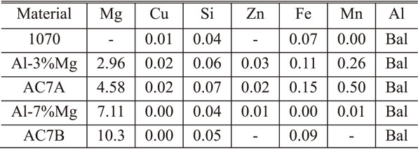
The UDTRC3) was used because conveying of as-cast strip is easy compared with the VHSTRC. A schematic of the UDTRC is shown in Fig. 1. AC7A aluminum alloy (hereinafter referred to as AC7A), which is an Al–Mg alloy, was used. The chemical composition of this alloy is close to 5182,7) which is used for the inner paneling of automobiles. The chemical composition of AC7A is shown in Table 1. Coil springs were used for setting the roll load. The load was set by the length of the coil spring before pouring the molten metal, and this load is referred to as the roll load. The roll load is measured by unit width, and the values used were 4, 10, 20, 50, 100, and 300 N/mm. Roll speed was 30 m/min, solidification length was 200 mm, and pouring temperature of the molten metal was 675°C. Surface cracks of the as-cast strip were investigated visually after solvent removable dye penetrant testing (ALP-TP and ALP-TD, Trusco Nakayama Co., Japan). The solvent removable dye penetrant testing is hereinafter referred to as color checking. The surface cracking on the lower roll side of the strip was worse than on the upper roll side, and the lower roll side of the strip was investigated in this study.

Schematic illustration of unequal-diameter twin-roll caster.
A conventional pouring method for the UDTRC and two proposed types of pouring methods of molten metal are shown in Fig. 2. Figure 2(a) shows the conventional pouring method,3) wherein molten metal is poured in the molten metal pool on the lower roll. Figures 2(b) and (c) are the molten metal pouring methods proposed in the present study. In Fig. 2(b), the molten metal was poured at the edge of the molten metal pool on the lower roll through the launder. In our previous research on cooling slopes, the pouring angle of the molten metal against the cooling slope affected the temperature of the molten metal after the metal was released from the cooling slope.8) It is inferred that the pouring angle of the molten metal against the roll surface influences the heat transfer between the molten metal and the roll. Angle α between the launder and the lower roll surface (hereinafter referred to as the pouring angle) was set to 0, 20, and 40 degrees to investigate strip thickness, surface condition, and surface cracking. When the molten metal was dropped on the rotating roll in a previous study, there were small dents on the surface of solidified pieces.9) The as-cast strip surface was flat and there were no dents when the strip was cast by the process in Fig. 2(a), with the molten metal poured into the molten metal pool.
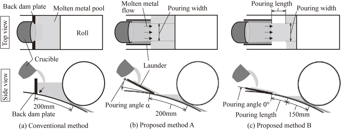
Three types of pouring methods used in this study: (a) conventional molten metal pouring, and proposed methods (b) A and (c) B.
It is thought that in the case where molten metal is poured on the rotating roll, the area in contact between the molten metal and the roll surface decreases due to the small dents; as a result, heat transfer between the molten metal and the roll surface decreases. In Fig. 2(c), there is a distance (hereinafter referred to as the pouring length) between the poured molten metal and the edge of the molten metal pool, and this is the difference between the methods shown in Figs. 2(b) and (c). The pouring length was adjusted by moving the tip position of the launder, and the values used were 0, 20, 30, 40, and 50 mm. Heat transfer between the solidification layer and the roll surface decreases as the solidification length increases; in other words, heat transfer decreases as the solidification time increases.10) The cause of this is thought to be that the solidification layer is peeled from roll surface by solidification shrinkage. The thickness of the solidification layer is thin and the temperature of the solidification layer rapidly decreases with increasing pouring length. This means that the solidification shrinkage rapidly increases and thus the solidification layer rapidly peels from the roll surface. As a result, the heat transfer between the solidification layer and the roll surface remarkably decreases. Once the solidification layer peels from the roll surface, the peeled layer does not stick to the roll surface. The heat transfer between the solidification layer and the roll surface of Fig. 2(c) is smaller than that of Fig. 2(b), and the rate of increase of the thickness of the solidification layer of Fig. 2(c) is lower than that of Fig. 2(b).
In the experiment to investigate the effects of pouring length, the solidification length was 150 mm. The position of the molten pool surface was kept constant to maintain the solidification length at a constant value. It is thought that the solidification layer on the roll was semisolid when the roll load was 4 N/mm. In our previous study, surface cracking of AC7A strip cast at roll speeds of 10, 20, and 30 m/min reduced as the roll speed decreased.11) This means that the surface cracking decreases as the solidification time increases. It is thought that the temperature of the semisolid layer on the roll decreases and that the solid fraction increases as the pouring length increases. As a result, the strength of semisolid layer increases and surface cracking decreases. The solidification layer with the pouring length of Fig. 2(c) is thinner than that at the solidification length in Fig. 2(b) because the quantity of molten metal at the pouring length is less than at the solidification length. The rate of increase of the solidification layer at the pouring length is greater than that at the solidification length. The width of the molten metal at the tip of the launder is hereinafter referred to as the pouring width, as shown in Figs. 2(b) and (c). In Fig. 2(b), in the area outside of the boundary marked by the pouring width, solidification is the same as that of the conventional UDTRC. The heat transfer between the solidification layer and the roll surface decreases, and the thickness of the solidification layer decreases for the area within the pouring width and not outside the pouring width. In this case, it is thought that the thickness distribution becomes as shown in Fig. 3. At roll bite, the upper and lower solidification layers come into contact outside the pouring width boundary, but not within the pouring width boundary. It is therefore thought that the roll load decreases and thus surface cracks decrease at the pouring width. Outside of the pouring width, the molten metal is solidified by conventional roll load of the UDTRC, producing strip strong enough to be conveyed. In the method shown in Fig. 2(c), heat transfer decreases due to peeling from the roll surface at the pouring length, and thus heat transfer does not increase at the solidification length. In the case shown in Fig. 2(c), the thickness distribution of the solidified layer may become as shown in Fig. 312) when the heat transfer is small enough.
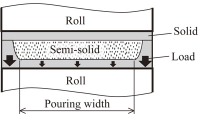
Diagram of predicted cross section of strip at roll bite for a strip cast using proposed model metal pouring method B or C.
AC7A was used for the method shown in Fig. 2(a), AC7A and Al–3%Mg were used for the method in Fig. 2(b), and Al–3%Mg, AC7A, Al–7%Mg, and AC7B aluminum alloy (hereinafter referred to as AC7B) were used for the method in Fig. 2(c). Al–3%Mg was made from AC7A and 1070 aluminum (hereinafter referred to as 1070). The chemical compositions of 1070, Al–3%Mg, AC7A, Al–7%Mg, and AC7B are shown in Table 1. The roll load was 300 N/mm and the roll speed was 30 m/min. The solidification lengths shown in Figs. 2(a) and (b) were 200 mm, and that in Fig. 2(c) was 150 mm. For the conventional UDTRC shown in Fig. 1, strip can be cast at a superheat of 40°C, and a superheat of 40°C was adopted in this study. Pouring temperatures of Al–3%Mg, AC7A, Al–7%Mg, and AC7B were 685°C, 675°C, 665°C, and 650°C, respectively. The weight of cast aluminum alloy was about 3.5 kg and about 3000 mm of strip was cast. Observation of the surface cracks, optical microscopy of the cross-sectional microstructure, 3-point bending test, deep drawing test, and tension test were conducted. Color checking was conducted to investigate the surface cracks. The microstructure of the cross-section was investigated using an optical microscope. 5% hydrofluoric acid solution or Weck’s reagent,13,14) which is sensitive to solid solution of element, were used for etching. Three-point bending test was conducted on as-cast strip to investigate the surface cracks. The radius curvature of the punch was 15 mm, and the lower roll side of the strip was the outer side in the testing. As-cast strip was cold-rolled down to 1 mm and annealed at 370°C for 1.5 h to make the specimens for deep drawing. Blanks (disk-shaped specimens) for deep drawing were made from inside of the pouring width of the strip. The diameter of the punch was 32 mm, the radius curvature of the shoulder of the punch was 3 mm, the diameter of die hole was 34.1 mm, and the radius curvature of the shoulder of the die was 3.5 mm. The pressure of the blank holder was 2.4 kN. The outer surface of the cup was the lower roll side surface of the strip. As-cast strip was cold-rolled down to 1 mm, and annealed at 360°C for 1.5 h to make the specimens for tension tests. The tension test was conducted in both the casting direction and the width direction. The shape of the test piece for the tension test is shown in Fig. 4. The gauge length was 9 mm and the width was 5 mm.
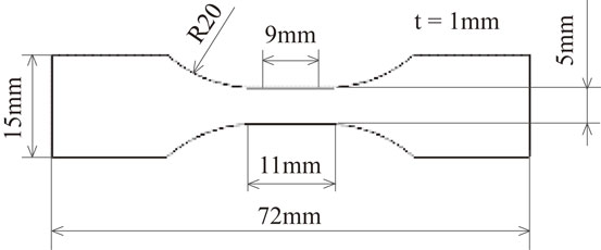
Test piece of for tension test.
AC7A strip was cast at roll loads ranging from 4 to 300 N/mm. Color checking was conducted on the lower roll side of the as-cast strip. Lower roll side strip surfaces without and with color checking are shown in Fig. 5. Ripple marks15) became less evident as the roll load decreased, and did not occur when the roll load was smaller than 10 N/mm. There was a tendency for the metallic luster on the strip surface to become poor and for the surface to become dull white, but the surface cracks decreased as the roll load decreased. When the roll load was 4 N/mm, surface cracks did not occur. It became clear that small roll load was useful to prevent surface cracking in AC7A strip. However, the strip was easily broken at 4 N/mm of roll load, and continuous conveying of as-cast strip was difficult. It is thought that the strip broke due to insufficient strength as the strip did not completely solidify. Both the reduction of surface cracks and improvement of ease of conveying the as-cast strip were attempted using the method shown in Section 3.2.
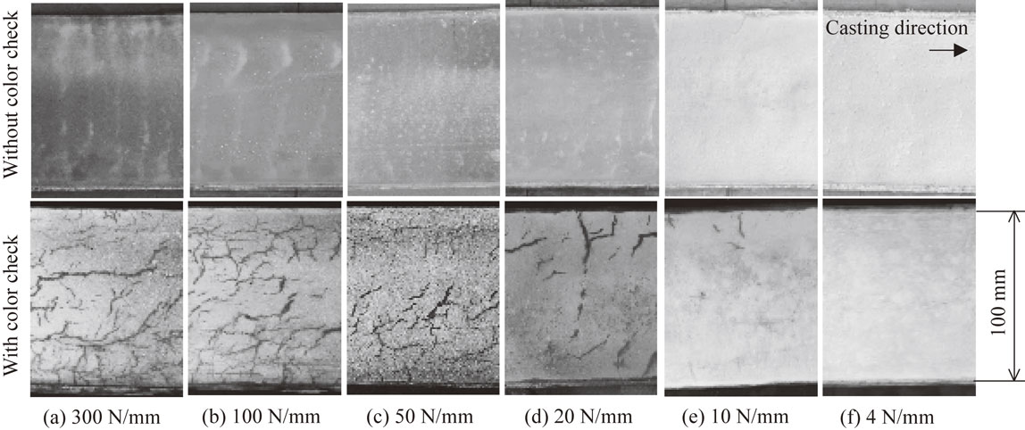
Images of surface cracks in AC7A strips cast using unequal-diameter twin-roll caster with different roll loads.
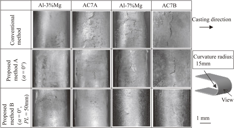
Lower roll side surfaces of the AC7A strips cast using the methods shown in Figs. 2(a) and (b) are shown in Fig. 6, and the strip thickness is shown in Fig. 7. Ripple marks appeared on the strip shown in Fig. 6(a) when the strip was cast using the UDTRC with the conventional molten metal pouring method shown in Fig. 2(a). Small grooves in the casting direction were visible when the surface was observed using a stereo microscope. It is thought that these small grooves were caused by scratches from solidified metal stuck to the back dam plate. Color checking showed that there were a lot of cracks on the strip surface. When the molten metal was poured on the roll surface using the method in Fig. 2(b), a white matte area similar to the ripple marks were observed within the pouring width for the conditions shown in Figs. 6(b), (c), and (d). When the white matte area was observed by stereomicroscope, there were inconsistent directional grooves, in contrast to the grooves in Fig. 6(a), which were parallel to the casting direction. The cause of these grooves is thought to be as follows. In Fig. 2(a), the molten metal was poured directly into the molten metal pool, and the molten metal was sheared to the rotation direction of the roll when it contacted with the roll surface. The direction of the grooves in Fig. 6(a) is therefore the rotation direction of the roll. An oxide film (indicated by the arrow in Fig. 2(a)) was formed on the molten metal surface at the corner formed by the back dam plate and the roll, as the molten metal was in contact with the air. This oxide film was broken by the shear from the roll, and the molten metal beneath the film came into contact with the roll. As a result, the area where the molten metal was in contact with the roll had a metallic luster. The velocity component of the poured molten metal in the rotating direction of the roll was faster than the roll speed when the launder was used. Also, the direction of the poured molten metal was not constant when the launder was used. Therefore, there were grooves with varying directions when the strip was cast using the method in Fig. 2(b). The thickness of the launder was 2 mm and the difference of level between the launder and roll surface was 2 mm. The molten metal was thus in contact with the atmosphere for 2 mm of level difference and the oxide film was formed on the surface of this molten metal. This oxide film was not broken by the rotation of the roll and the molten metal on the film did not come into contact with the roll. As a result, the strip surface was matte white. It is thought that the oxide film corresponds to the matte white area of the ripple marks were formed before the molten metal coming into contact with the roll surface.2) Considering that the strip surface was matte white inside of the pouring width, the oxide film is thought to have existed on the molten metal surface before coming into contact with the roll. The heat transfer between the molten metal and the roll at the matte white area of the strip surface was smaller than that at the metallic luster area. The surfaces of the strips in Figs. 6(b), (c), and (d) were not flat, and heat transfer between the molten metal and the roll surface was smaller than for the strip in Fig. 6(a). Cracks occurred under the conditions for Fig. 6(b) (pouring angle α = 40 degrees) at the pouring width, and cracks did not occur for Figs. 6(c) and (d), which had conditions of pouring angle α smaller than 20 degrees. Cracks occurred outside the pouring width for Figs. 6(c) and (d). Roll load was mainly supported from outside of the pouring width, and thus the roll load within the pouring width became smaller. As a result, the cracks within the pouring width decreased for Figs. 6(c) and (d). The strip could be continuously conveyed because the strength of the strip outside of the pouring width was greater due to having cooled sufficiently like with the conventional UDTRC. The strip thickness decreased as the pouring angle α decreased as shown in Fig. 7. The molten metal velocity component vertical to the roll surface decreased as the pouring angle decreased, and as a result, the heat transfer between the molten metal and the roll surface decreased as the pouring angle decreased. In the CTRCA, the edges where cracks occurred are trimmed.16) In the same way, the edges outside of the pouring width, where cracks occurred, can be trimmed in a later process. The lower roll side surface of the Al–3%Mg strip cast using the Fig. 2(b) (α = 0 degrees) is shown in Fig. 8. Cracks occurred within the pouring width of the Al–3%Mg strip. The Al–Mg strip was semisolid at roll bite where the strip was loaded. It was reported that the strength of semisolid Al–3%Mg is weak compared to semisolid Al–Mg with Mg content greater than 3%.17) It was also reported that the latent heat of the Al–Mg alloy increases as the Mg content decreases.18) It is thought that the solid fraction of semisolid Al–3%Mg was lower than semisolid Al–Mg with Mg content is greater than 3%, and thus the strength was also lower, resulting in cracks. The method depicted in Fig. 2(c), which includes a pouring length, was proposed to increase the strength of the Al–3%Mg by lowering the temperature and thus increasing the solid fraction. The free surface (non-roll contacting side) of the solidification layer at the pouring length was looked like the molten metal or the semisolid metal. The lower roll side surface of the Al–3%Mg strip cast using the method in Fig. 2(c) is shown in Fig. 9. There was a tendency for cracks within the pouring width to decrease as the pouring length increased, and cracks did not occur at 50 mm of pouring length. The solidification time increased as the pouring length increased, and the temperature of the solidification layer decreased in the molten metal pool, too. As a result, the strength of the strip increased. It is estimated that the strength or ductility of the Al–3%Mg strip was lower than that of the AC7A right after the molten metal coming into contact with the roll surface. Therefore, the pouring length of the Al–3%Mg must be set longer than that of the AC7A to increase the strength sufficiently to endure the roll load and to prevent cracking. The solid fraction increased due to decreasing temperature as the pouring length increased, and cracks did not occur from the roll load when the strip strength was sufficiently increased. The strip thicknesses at pouring lengths of 0 mm and 50 mm were 3.35 mm and 3.44 mm, respectively. There was not a remarkable difference between the thicknesses of strips cast at 0 and 50 mm of the pouring length. The effect of the pouring length on the thickness of the solidification layer was thus small. The small heat transfer between the solidification layer and the roll surface is thought to be the cause of the small increase of the strip thickness. Color checking was conducted on the surfaces of the Al–Mg strips cast using the method in Fig. 2(c) with 50 mm of pouring length, as shown in Fig. 10. The surface cracking of the Al–Mg strips decreased within the pouring width. It became clear that the proposed method in Fig. 2(c) was useful to reduce surface cracks in Al–Mg strips.
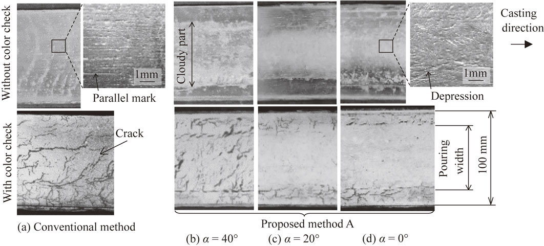
Images of surface cracks of AC7A strips cast with different molten metal pouring method. Pouring methods are shown in Fig. 2.

Strip thickness of cast AC7A strips plotted against pouring angle used for proposed pouring method A, along with that for conventional method.

Surface cracks in an Al–3%Mg strip cast using proposed pouring method A (α = 0°).
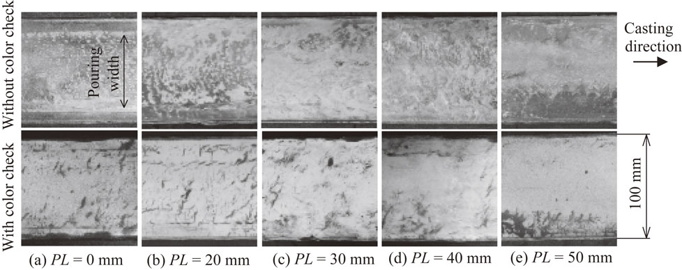
Images of surface cracks in Al–3%Mg strips cast using proposed pouring method B with different pouring lengths.

Surface cracks in Al–Mg alloy strips with different Mg contents cast using proposed pouring method B. Strips were color checked.
The microstructure of the cross-sections of the AC7A strip cast using the methods in Fig. 2 are shown in Fig. 11. It was reported by Kumai and Harada that a band area consisting of globular crystals exists at the center of the thickness direction of Al–Mg strip cast using the VHSTRC.5) This band area was found in Al–Mg strips cast using the UDTRC. The widths of the band areas of the strip cast using the proposed pouring methods in Figs. 2(b) and (c) were wider than that of the strip cast using the conventional pouring method in Fig. 2(a). The cross-sections of the strips cast using the methods in Figs. 2(b) and (c) were similar to the predicted cross-section shown in Fig. 3, and this is the cause of the wide band area. The strips cast using the methods in Figs. 2(a), (b), and (c) were etched using 5% hydrofluoric acid solution, and grains near the surface of the strips cast using the methods in Figs. 2(b) and (c) were larger than that of the strip cast using the method in Fig. 2(a). This suggests that the heat transfer between the molten metal and the roll surface was small, and as a result, the cooling rate of the strip cast using the proposed pouring methods in Figs. 2(b) and (c) was lower compared with the conventional pouring method (Fig. 2(a)) with the UDTRC. As-cast strip was cold-rolled down to 1 mm-thick plate and the microstructure of the cross-section was observed. The thickness of the band area of the cold-rolled plate from strips cast using the methods in Figs. 2(b) and (c) became thinner than that of the strip cast using the method in Fig. 2(a). The as-cast strip was cold-rolled down to 1 mm thick and annealed at 360°C for 1.5 h. The microstructures after cold rolling and annealing of the strip cast using the methods in Figs. 2(b) and (c) were more uniform than that of the strip cast using the conventional method in Fig. 2(a).
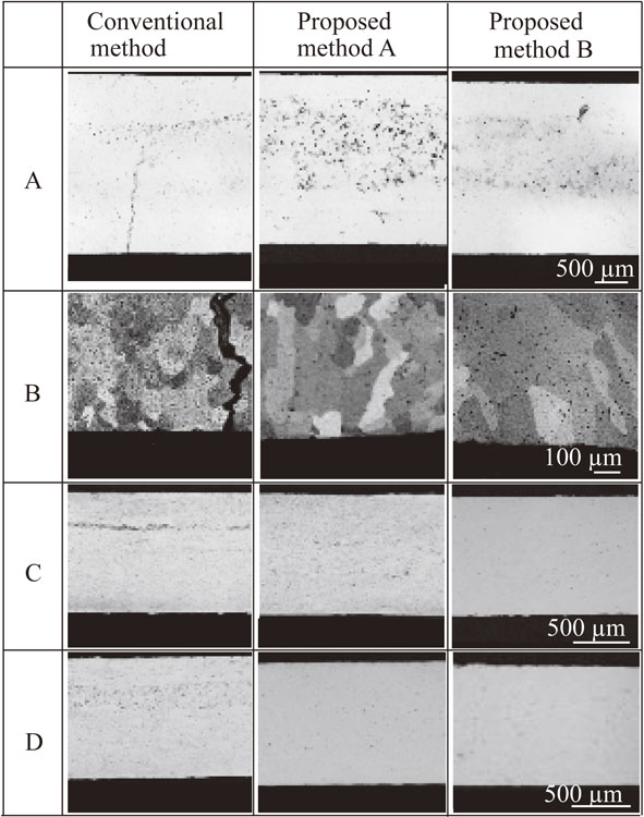
Cross sections of AC7A strips cast with different pouring methods. A: As-cast strips. B: Enlarged view near lower roll contact surface. C: Cold-rolled down to 1 mm. D: Cold-rolled down to 1 mm and annealed at 360°C for 1.5 h.
The AC7A strips cast using the methods in Figs. 2(a) and (b) were etched using Weck’s regent, and the near surfaces of the strips are shown in Fig. 12. Harada reported that a solution-rich liquid inside of the strip cast using the HSTRC was squeezed to the surface by roll load, causing cracks to occur at the position of the solution-rich liquid.5) There was segregation of Mg, which appears to be due to exhaustion, on the upper roll side of the strip cast using the method in Fig. 2(a), as shown in Fig. 12.
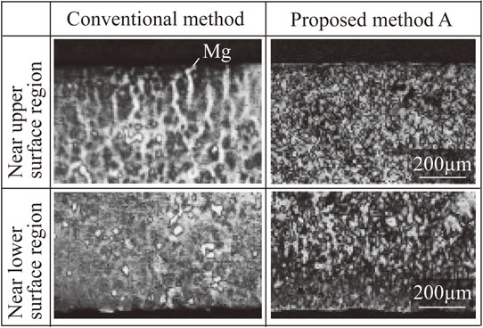
Images of cross sections of near-surface regions of AC7A strips cast with different pouring methods. Weck’s reagent was used for etching. The arrow shows exude to surface of Mg.
Segregation of Mg did not occur on the lower roll side of the strip cast using the method in Fig. 2(a). However, cracks did occur in this strip, as shown in Fig. 6. It is thought that the exhaustion of solution-rich liquid Mg was not the direct cause of the cracking, but instead the roll load was. Exhausted solution-rich liquid Mg was not observed on the surfaces of the strips cast using the method in Fig. 2(b) (α = 0 degrees). The roll load of this method is smaller than that of the conventional UDTRC in Fig. 2(a). Therefore, the semisolid layer was pushed by a small load and exhaustion of solution-rich liquid Mg did not occur.
3.2.3 Three-point bending testResults of three-point bending test of the strips cast using the molten metal pouring methods in Fig. 2 are shown in Fig. 13. Surface cracks occurred in all tested Al–Mg alloys strips cast using the conventional method shown in Fig. 2(a). The AC7A and the AC7B were broken by three-point bending tests. Surface cracks were reduced by the method in Fig. 2(b) (α = 0 degrees). However, surface cracks still occurred on the Al–7%Mg and AC7B strips. For the strips cast by the method in Fig. 2(c) (α = 0 degrees) with 50 mm pouring length, all Al–Mg alloys could be bent at 180 degrees without surface cracking. Surface cracks of the strip cast using the method in Fig. 2(a) might have affected the cracks made in the three-point bending test.
Surface cracks of cast strips after bending test for Al–Mg alloy strips with different Mg contents and with different pouring methods.
Cups made by deep drawing test of the AC7A strip cast using the methods in Fig. 2 are shown in Fig. 14. The strip cast using the method in Fig. 2(a) was broken at punch shoulder during drawing, as shown in Fig. 14(a). The surface cracks shown in Fig. 6(a) might have affected this breakage. The strip cast by the method in Fig. 2(b) could be drawn without breaking, as shown in Fig. 14(b), in spite of developing surface cracks. Fine cracks on the strip surface might have affected these cracks during deep drawing. The strip cast using the method in Fig. 2(c) could be deep drawn without cracking as shown in Fig. 14(c), and the limiting drawing ratio (LDR) was 1.9. The strip cast using a single roll caster equipped with a scraper does not have a band area, and the LDR of this strip is 2.0. The LDR of the strip cast using the method in Fig. 2(c) was inferior to the LDR of the strip cast using the single roll caster equipped with the scraper. The cause of this might be the band area, which is visible in the strip cast using the method in Fig. 2(c); however, the mechanism of effect of this band area on the LDR is not clear.
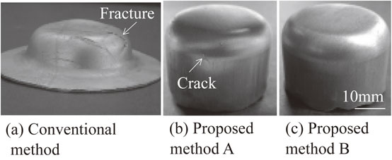
Photographs of cups made by deep drawing test of AC7A strips cast using different pouring methods: (a) conventional pouring method and proposed methods (b) A and (c) B. Strips were cold-rolled down to 1 mm, annealed at 360°C for 1.5 h, and cup-tested.
Tension test results of the AC7A strips cast using the methods in Figs. 2(a) and (b) are shown in Fig. 15. The elongations of the strip cast using the method in Fig. 2(a) in the casting direction and the width direction were 24% and 6%, respectively. Elongation might be influenced by texture anisotropy caused by cold rolling and also by surface cracks. The elongations of the strip cast using the method in Fig. 2(b) in the casting direction and the transverse direction were 30% and 20%, respectively. The elongation was remarkably improved by the molten metal pouring method in Fig. 2(b) compared to the method in Fig. 2(a). The tensile stress and the proof stress in the transverse direction were also remarkably improved by the method in Fig. 2(b) compared to the method in Fig. 2(a). It is estimated that the improvement of the tension test results was caused by the decrease in surface cracks.

Result of tension tests of AC7A strips. Strips were cold-rolled down to 1 mm and annealed at 360°C for 1.5 h to make test pieces. Con: Conventional method, Pro.A: Proposed method A (α = 0°). CD: Casting direction, TD: Transverse direction.
In this paper, reduction of surface cracking in Al–Mg alloys strips cast using an unequal diameter twin roll caster was attempted with different molten metal pouring methods, and the conclusions are as below.
We are grateful to Professor Kumai of the Tokyo Institute of Technology and Assistant Professor Harada of the Tokyo Institute of Technology (present Associate Professor, Tokyo Denki University) for their support in the etching using Weck’s regent and the microstructure observations.