Abstract
Due to its exceptional high temperature mechanical properties and low density, TiAl alloy has emerged as a promising structural material for high temperature applications. However, the inherent brittleness and susceptibility to cracking pose challenges during processing. In the additive manufacturing process of TiAl alloy, substrate preheating plays a crucial role in mitigating crack formation. This study focuses on the fabrication of crack-free Ti-48Al-2Cr-2Nb alloy via laser directed energy deposition (LDED), investigating the influence of preheating on sample cracks and microstructure. The results demonstrate that substrate preheating significantly affects the quality of formed samples. Without preheating, numerous cracks are observed in the samples; however, their severity gradually decreases with increasing preheating temperature. Notably, when the substrate was heated to 400°C, no cracks were detected in the samples. Moreover, higher preheating temperature lead to reduced grain length-diameter ratio and partial equiaxed crystal formation along with increased average grain size and α2 phase proportion while decreasing average orientation difference slightly. The microhardness exhibited a subtle declining tendency. With an increase in the proportion of α2 phase, the stress generated between different phases is reduced. Additionally, increasing the preheating temperature reduces dislocation density and releases stress, thereby inhibiting crack generation.
1. Introduction
The TiAl alloy exhibits several advantageous properties, including low density, high specific strength and stiffness, excellent flame retardancy, superior resistance to high temperature oxidation and creep. Consequently, it is considered as a promising candidate for high temperature structural applications in both aerospace and civil industries. Moreover, it is anticipated that the TiAl alloy could potentially replace nickel-based superalloys within the service temperature range of 650∼800°C.1,2) Therefore, TiAl alloy have been employed as lightweight high-temperature structural materials in the new generation of aerospace aircraft and engines, encompassing high-pressure compressor blades, low-pressure turbine blades, shells, connecting rods, among others.3–5) The additive manufacturing technology emerged in the late 1980s as a novel manufacturing technique.6) Compared to traditional material removal (cutting processing) techniques, this manufacturing method employs a “bottom-up” approach for material accumulation. It offers notable advantages such as enhanced flexibility, mold-free production, shortened cycle times, increased material utilization rates, and the ability to fabricate challenging materials. Consequently, it is highly suitable for producing intricately shaped components.7,8) Laser additive manufacturing encompasses laser directed energy deposition (LDED) and laser powder bed fusion (LPBF). In contrast to LPBF, LDED enables the fabrication of gradient materials through precise adjustments in scanning and powder delivery rates. Additionally, the utilization of independent nozzles and powder silos offers the potential for in situ alloy mixing and production of gradient materials, resulting in objects possessing a ductile core with hard, wear-resistant surfaces. LDED process exhibits exceptional flexibility, making it highly suitable for the maintenance of large mechanical or structural components. Moreover, LDED enables the integrated manufacturing of multi-materials and multi-structures within parts, such as double alloy integral blade disks and impellers. The laser directed energy deposition equipment exhibits excellent versatility, and the implementation of a synchronized heat source (such as resistance or induction heating device, secondary laser source) enables effective mitigation of internal stress and controlled prevention of cracks. In the process of LDED, the material undergoes rapid melting, solidification, and cooling, leading to the accumulation of high internal stress within the sedimentary layer. Consequently, cracks and other defects are prone to occur under the stress induced by laser additive action.9–11) Cracks are more prone to occur, particularly in TiAl alloys exhibiting limited plastic deformation ability and low ductility at room temperature.12,13) Based on relevant studies, the thermal cycle characteristics of additive manufacturing are significantly influenced by ambient temperature. Therefore, investigating the impact of substrate preheating temperature on additive manufacturing is highly significant for academic research.14) The preheating of the substrate has been observed to mitigate the propensity for crack formation during the laser additive process of TiAl alloy.15,16) The effect of substrate temperature on the microstructure and hardness of TiAl alloy processed of SLM was investigated by Li,17) revealing a gradual decrease in both α2 phase content and hardness with increasing substrate temperature. Xu18) achieved the production of a crack-free coating by substrate preheating, resulting in an enhanced tensile property at room temperature compared to that of the cast sample. The substrate preheating not only mitigates thermal stress and crack susceptibility, but also exerts a pronounced influence on the microstructure and mechanical properties of laser additive manufacturing.19) However, limited research has been conducted on the impact of substrate preheating on crack formation, microstructure evolution, and mechanical properties of Ti-48Al-2Cr-2Nb alloy by LDED. This study investigates the effect of substrate preheating on crack formation, microstructure evolution, and microhardness in Ti-48Al-2Cr-2Nb alloy fabricated by LDED, providing theoretical support for the widespread application of LDED in TiAl alloy preparation.
2. Experimental Procedure
2.1 Process and materials
The material was Ti-48Al-2Cr-2Nb alloy powder with a particle size of 53∼150 µm, and its chemical composition is shown in Table 1. The substrate material was Ti-6Al-4V with a thickness of 10 mm. Prior to the experiment, sandpaper should be used to remove the oxide film from the surface of the substrate, while alcohol should be employed for eliminating impurities such as oil. The LDM-4030 powder feeding laser additive manufacturing equipment produced by Nanjing Raycham Laser Technology Co., LTD. To prevent oxidation during deposition, argon gas was filled as a protective gas before testing to maintain oxygen content below 10 ppm within the chamber. The experiment involved a single track laser directed energy deposition test, resulting in the deposition of five layers. The single track laser directed energy deposition test was conducted, with a deposition length of 30 mm and a total of five layers. The preheating device utilizes a resistance heating temperature controller beneath the substrate, with the heater constructed from cast copper. Laser directed energy deposition experiments were carried out under the conditions of no preheating, preheating temperature of 200°C and 400°C respectively. The primary process parameters were as follows: laser power P = 1800 W; travel speed V = 6 mm/min; powder feed rate D = 0.8 rad/min. After completion of deposition, samples were embedded, polished and etched using an etching solution (HF:HNO3:H2O volume ratio 1:1:8) for a duration of 25 s followed by preparation of metallographic samples.
Table 1 Composition of Ti-48Al-2Cr-2Nb alloy (wt/%).

The morphologies and elements were examined using an Olympus GX51 optical microscope (OM), a TESCAN MIRA3 field emission scanning electron microscope, an energy dispersive spectrometer (EDS), and an electron backscattering diffraction (EBSD) technique. The EBSD data was analyzed utilizing the Channel 5 software. The microhardness of the sample was measured using an HVS-1000A microhardness tester with test parameters set at a load of 200 g and a holding time of t = 15 s.
3. Results and Discussions
3.1 Macroscopic morphology analysis
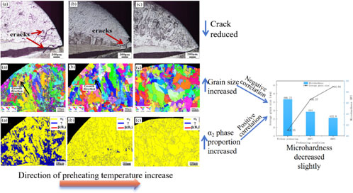
The macroscopic morphology of samples prepared under different preheating conditions is depicted in Fig. 1. It can be observed from the figure that an increase in preheating temperature leads to a gradual reduction in crack formation and an expansion in sample width. This indicates that the generation of cracks can be effectively suppressed by elevating the preheating temperature of the substrate.
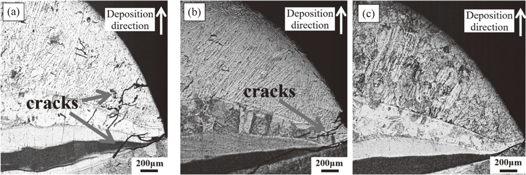
3.2 Microstructure analysis
The microstructure of the sample under different preheating conditions is illustrated in Fig. 2. With increasing preheating temperature, the width of columnar crystals gradually increases. Cracks were observed at the fusion edge of the sample without preheating. According to relevant literature reports, in the process of laser processing, cracks are most likely to occur at the joint, which produces a higher temperature gradient at the joint, resulting in a greater stress.20–22) At a preheating temperature of 200°C, a few cracks appeared at both the fusion line and the edge of the molten pool. However, no cracks were observed in samples preheated to 400°C due to reduced temperature gradient during laser directed energy deposition and subsequent stress reduction.23) As depicted in Fig. 5(a), the sample without preheating exhibits the presence of α2 phase (Ti3Al) along with a minor quantity of B2 phase. The B2 phase is the ordered structure of the β-Ti. According to literature reports, the coefficient of thermal expansion for the α2 phase and B2 phase at room temperature is reported as 3.26 × 10⁻⁵ K−1 and 1.45 × 10⁻⁵ K−1, respectively.24–26) Notably, the B2 phase exhibits a more pronounced dependence on temperature, resulting in an increasing disparity in thermal expansion coefficients with rising temperatures. Consequently, this significant mismatch between the α2 and B2 phases’ coefficients of thermal expansion gives rise to substantial thermal residual stresses near the interface region during laser directed energy deposition processes, ultimately leading to crack formation.
The microstructure of Ti-48Al-2Cr-2Nb alloy fabricated by LDED is illustrated in Fig. 3(a), (b), and (c). It can be observed that the sample predominantly exhibits an α2/γ lamellar structure. As the preheating temperature increases, there is a corresponding increase in the spacing of the lamellar structure, accompanied by coarsening phenomena. EDS analysis results of sample elements at different preheating temperatures are presented in Fig. 3(d), (e), (f) and Table 2. The measured regions in Fig. 3(a), (b), and (c) are indicated by the black areas in Fig. 3(d), (e), and (f). The ratio of Ti and Al contents to their respective atomic weights, as listed in Table 2, is utilized. Determine the ratio of atomic numbers between Ti and Al. With increasing preheating temperature, the content of Al element gradually decreases. The atomic number ratio of Ti to Al in the sample without preheating is 1.3:1, indicating the coexistence of γ phase (TiAl) and α2 phase (Ti3Al). At a preheating temperature of 200°C, the atomic ratio of Ti and Al is 2.2:1, suggesting a significant presence of α2 phase with a minor amount of γ phase in the sample. When the preheating temperature reaches 400°C, the atomic number ratio of Ti to Al approaches 3:1, indicating that the sample mainly consists of α2 (Ti3Al) phase.

Table 2 Results of energy spectrum analysis (wt%).

To further investigate the impact of substrate preheating on the microstructure, EBSD analysis was conducted on samples prepared under different preheating conditions. As depicted in Fig. 4, an evident coarsening of grains is observed with increasing preheating temperature. In the absence of preheating, columnar crystals grow along the direction of the highest cooling rate, resulting in an average grain size of 18.35 µm. When preheated to 200°C, a reduction in length-diameter ratio of grains occurs alongside the formation of a few equiaxed crystals, leading to an average grain size of 36.57 µm. Preheating at 400°C results in indistinct crystal growth orientation and a smaller length-to-diameter ratio. Notably, coarse equiaxed crystals are formed within the sample’s central region, yielding an average grain size of 44.04 µm. This is attributed to the joint influence of the temperature gradient G and solidification speed VS on determining the morphology, size, and internal substructures of grains in the molten pool during solidification. A smaller G/VS ratio facilitates the formation of equiaxial crystals, whereas a larger ratio promotes columnar crystal growth.27) With the elevation of preheating temperature, the reduction in temperature gradient and prolongation of holding time within the α + γ phase region contribute to the formation of equiaxed crystals and an augmentation grain size.28)

The phase constituent of sample preparation under different preheating temperatures is illustrated in Fig. 5. The unpreheated sample primarily consists of the γ phase, α2 phase, and a small amount of B2 phase, with an uneven distribution of the γ phase throughout the sample. Specifically, the γ phase accounts for 31.7% while the α2 phase accounts for 58.2%. Conversely, when subjected to preheating at 200°C and 400°C, the sample exhibits a uniform phase distribution predominantly composed of the α2 phase along with a minor presence of the γ phase. The proportion of the α2 phase gradually increases with the rise in preheating temperature. This is contrary to previous research findings.29) Compared to SLM, LDED exhibits a higher energy input, which further increases with elevated preheating temperatures. Additionally, it is noteworthy that the saturated vapor pressure of aluminum is comparatively lower than of titanium.30) Large energy inputs result in Al loss.31) Referred to in conjunction with the phase diagram of TiAl alloy (Fig. 6),32) it becomes evident that, with the decrease in aluminum content, the solid-liquidus of the TiAl alloy phase diagram will shift towards an aluminum-deficient direction, leading to the precipitation of the brittle α2 phase. By comparing the crack morphology depicted in Fig. 2, it is evident that a higher preheating temperature can effectively suppress crack formation. This phenomenon can be attributed to the reduction in dislocation density (Fig. 8) and subsequent release of residual stress induced by preheating. On the other hand, according to relevant studies, cracks are prone to occur in the vicinity of the interface between the α2 phase and B2 phase. As the preheating temperature increases, the proportion of γ phase and B2 phase gradually decreases, while the proportion of α2 phase increases. At a temperature of 400°C, the predominant phase constituent is near α2 phase. According to relevant literature, cracks tend to occur near the interface between α2 and B2 phases. The formation of a predominantly α2 single phase (Fig. 5(c)) can effectively mitigate or eliminate cracks by reducing the occurrence of an α2-B2 interface.33)


The kernel average misorientation (KAM) of the sample under different preheating conditions is illustrated in Fig. 7. The KAM value serves as an indicator for the dislocation density and stress distribution within the sample, commonly employed to assess these properties. A higher KAM value corresponds to a greater overall dislocation density.34,35) According to the local orientation difference curve under different preheating conditions in Fig. 7(a), the cumulative local orientation difference of the sample was determined and presented in Fig. 7(b). As the preheating temperature increases, a gradual decrease in the cumulative local orientation difference suggests a reduction in overall dislocation density. This phenomenon occurs due to the migration of dislocations within the grain towards the grain boundary under the influence of preheating temperature, which is counteracted by partial opposite dislocations at the grain boundary, thereby reducing residual stress levels in each region.36)

The distribution of local orientation difference of samples under different preheating conditions is illustrated in Fig. 8. It can be observed from the figure that a high KAM value exists at the phase boundary, while the distribution of local orientation difference gradually decreases with increasing preheating temperature. In the absence of preheating, there is a high dislocation density at the grain boundaries of fine grains, exhibiting a dense distribution. At a preheating temperature of 200°C, the dislocation density distribution becomes relatively dispersed in the sample. Moreover, when the preheating temperature reaches 400°C, the dislocation density in the coarse equiaxed grain region located in the middle section of the sample reaches its lowest point. This phenomenon can be attributed to an increase in preheating temperature which leads to partial release of residual stress.
3.3 Microhardness analysis
The deposited Ti-48Al-2Cr-2Nb alloy is primarily composed of α2 and γ phases. The α2 phase exhibits a close-packed hexagonal lattice structure with limited slip systems, rendering it a brittle phase with higher hardness than the γ phase.37) According to the Hall-Petch formula, there exists an inverse relationship between grain size and material hardness, whereby larger grain sizes correspond to lower levels of hardness.38–40) Previous studies have demonstrated that an increase in preheating temperature leads to a reduction in the proportion of the α2 phase and a decrease in microhardness.17,41) According to the findings of this study, as depicted in Fig. 9, an increase in preheating temperature leads to a higher proportion of α2 phase (Fig. 5), while exhibiting a marginal decline in microhardness. This phenomenon arises from the mutual counteraction between the formation of a brittle phase (α2 phase) and the alteration in grain size. The slight decrease in microhardness indicates that the influence of grain size on microhardness is higher than the relative microhardness of generated α2.

4. Conclusion
This study investigates the impact of various substrate preheating temperatures on cracks, microstructure and mechanical properties of Ti-48Al-2Cr-2Nb alloy via LDED. The findings can be summarized as follows:
-
(1)
With the increase in preheating temperature, the predominant phase of the sample shifts towards α2 phase, thereby reducing interphase stress. Simultaneously, higher preheating temperatures result in a decrease in dislocation density, facilitating stress release and ultimately leading to crack reduction. When the preheating temperature reaches 400°C, crack-free samples can be successfully prepared.
-
(2)
With the increase in preheating temperature, there is an observed expansion in lamellar spacing. Simultaneously, a reduction in the length-diameter ratio of grains and an augmentation in average grain size are evident.
-
(3)
Microhardness slightly decreases with increasing preheating temperature.
Acknowledgments
The authors would like to acknowledge the financial supports provided by the National Key Research and Development Program of China (2022YFB4602202) and Liaoning BaiQianWan Talents Program (LNBQW 2020B0050).
REFERENCES
- 1) R. Xu, M. Li and Y. Zhao: J. Alloy. Compd. 932 (2023) 167611. doi:10.1016/j.jallcom.2022.167611
- 2) Z.G. Xue, Y.X. Huang, Y.T. Wang and X.J. Hai: Mater. Sci. Forum 747–748 (2013) 77–84. doi:10.4028/www.scientific.net/MSF.747-748.77
- 3) A. Nochovnaya, P.V. Panin, A.S. Kochetkov and K.A. Bokov: Metal Sci. Heat Treat. 56 (2014) 364–367. doi:10.1007/s11041-014-9763-4
- 4) B.P. Bewlay, S. Nag, A. Suzuki and M.J. Weimer: Mater. High Temp. 33 (2016) 549–559. doi:10.1080/09603409.2016.1183068
- 5) X.C. Ye, K.Q. Xiao, R.X. Cao, H. Wu, G.W. Zhao and B. Li: Vacuum 163 (2019) 186–193. doi:10.1016/j.vacuum.2019.02.028
- 6) M. Brandt: Laser Additive Manufacturing: Materials, Design, Technologies and Applications, (Woodhead Publishing, Duxford, UK, 2017).
- 7) B. Lu, D. Li and X. Tian: Engineering 1 (2015) 085–089. doi:10.15302/J-ENG-2015012
- 8) N. Li, S. Huang, G. Zhang, R. Qin, W. Liu, H. Xiong, G. Shi and J. Blackburn: J. Mater. Sci. Technol. 35 (2019) 242–269. doi:10.1016/j.jmst.2018.09.002
- 9) Y. Chen, K. Zhang, J. Huang, S.R.E. Hosseini and Z.L. Li: Mater. Des. 90 (2016) 586–594. doi:10.1016/j.matdes.2015.10.155
- 10) A. Mehta, L. Zhou, T. Huynh, S. Park, H. Hyer, S. Song, Y. Bai, D.D. Imholte, N.E. Woolstenhulme, D.M. Wachs and Y. Sohn: Addit. Manuf. 41 (2021) 101966. doi:10.1016/j.addma.2021.101966
- 11) S.Z. Uddin, L.E. Murr, C.A. Terrazas, P. Morton, D.A. Roberson and R.B. Wicker: Addit. Manuf. 22 (2018) 405–415. doi:10.1016/j.addma.2018.05.047
- 12) H.A. Soliman and M. Elbestawi: Int. J. Adv. Manuf. Technol. 119 (2022) 5583–5614. doi:10.1007/s00170-022-08728-w
- 13) J. Gussone, Y.C. Hagedorn, H. Gherekhloo, G. Kasperovich, T. Merzouk and J. Hausmann: Intermetallics 66 (2015) 133–140. doi:10.1016/j.intermet.2015.07.005
- 14) T.C. Dzogbewu: Manuf. Rev. 7 (2020) 35. doi:10.1051/mfreview/2020032
- 15) A. Weisheit, B.L. Mordike, W. Smarsly and K.H. Richter: Lasers Eng. 10 (2000) 63–81.
- 16) K. Osakada and M. Shiomi: Int. J. Mach. Tools Manuf. 46 (2006) 1188–1193. doi:10.1016/j.ijmachtools.2006.01.024
- 17) W. Li, J. Liu, Y. Zhou, S. Wen, Q. Wei, C. Yan and Y. Shi: Scr. Mater. 118 (2016) 13–18. doi:10.1016/j.scriptamat.2016.02.022
- 18) J. Xu, X. Lin, P. Guo, Y. Hu, X. Wen, L. Xue and W. Huang: Mater. Sci. Eng. 691 (2017) 71–80. doi:10.1016/j.msea.2017.03.046
- 19) C. Ding, X. Cui, J. Jiao and P. Zhu: Materials 11 (2018) 2401. doi:10.3390/ma11122401
- 20) T. Li, J. Xu, X. Bi and R. Li: Mater. Des. 223 (2022) 111126. doi:10.1016/j.matdes.2022.111126
- 21) Q. Guo, S. Chen, M. Wei, J. Liang, C. Liu and M. Wang: J. Mater. Eng. Perform. 29 (2020) 6439–6454. doi:10.1007/s11665-020-05163-4
- 22) X. Shi, H. Wang, W. Feng, Y. Zhang, S. Ma and J. Wei: Int. J. Refract. Met. Hard Mater. 91 (2020) 105247. doi:10.1016/j.ijrmhm.2020.105247
- 23) S.K. Rittinghaus, A. Weisheit, M. Mathes and W.G. Vargas: Proc. 13th World Conf. on Titanium, (Wiley, Hoboken, 2016) pp. 1205–1210. doi:10.1002/9781119296126.ch205.
- 24) M.S. Wang, E.W. Liu, Y.L. Du, T.T. Liu and W.H. Liao: Scr. Mater. 204 (2021) 114151. doi:10.1016/j.scriptamat.2021.114151
- 25) H.D. Shashikala, S.V. Suryanarayana, K.S.N. Murthy and S.V. Nagender Naidu: J. Less Common Met. 155 (1989) 23–29. doi:10.1016/0022-5088(89)90444-X
- 26) S. Fréour, D. Gloaguen, M. François and R. Guillén: Scr. Mater. 54 (2006) 1475–1478. doi:10.1016/j.scriptamat.2005.12.051
- 27) J.D. Hunt: Mater. Sci. Eng. 65 (1984) 75–83. doi:10.1016/0025-5416(84)90201-5
- 28) J. Tang, B. Huang, K. Zhou, W. Liu and Y. He: J. Mater. Sci. Lett. 20 (2001) 1863–1864. doi:10.1023/A:1012845422062
- 29) W. Li, J. Liu, Y. Zhou, S. Wen, Q. Wei, C. Yan and Y. Shi: Scr. Mater. 118 (2016) 13–18. doi:10.1016/j.scriptamat.2016.02.022
- 30) V. Juechter, T. Scharowsky, R.F. Singer and C. Körner: Acta Mater. 76 (2014) 252–258. doi:10.1016/j.actamat.2014.05.037
- 31) W. Kan, B. Chen, C. Jin, H. Peng and J. Lin: Mater. Des. 160 (2018) 611–623. doi:10.1016/j.matdes.2018.09.044
- 32) J.C. Schuster and M. Palm: J. Phase Equilibria Diffus. 27 (2006) 255–277. doi:10.1361/154770306X109809
- 33) M.S. Wang, E.W. Liu, Y.L. Du, T.T. Liu and W.H. Liao: Scr. Mater. 204 (2021) 114151. doi:10.1016/j.scriptamat.2021.114151
- 34) Z. Yan, D. Wang, X. He, W. Wang, H. Zhang, P. Dong, C. Li, Y. Li, J. Zhou, Z. Liu and L. Sun: Mater. Sci. Eng. 723 (2018) 212–220. doi:10.1016/j.msea.2018.03.023
- 35) L.P. Kubin and A. Mortensen: Scr. Mater. 48 (2003) 119–125. doi:10.1016/S1359-6462(02)00335-4
- 36) Y. Liu, G. He, Y. Yang, K. Li, H. Gong, B. Gan and C. Huang: J. Alloy. Compd. 870 (2021) 159518. doi:10.1016/j.jallcom.2021.159518
- 37) K. Kothari, R. Radhakrishnan and N.M. Wereley: Prog. Aerosp. Sci. 55 (2012) 1–16. doi:10.1016/j.paerosci.2012.04.001
- 38) M. Furukawa, Z. Horita, M. Nemoto, R.Z. Valiev and T.G. Langdon: Acta Mater. 44 (1996) 4619–4629. doi:10.1016/1359-6454(96)00105-X
- 39) Y.S. Sato, M. Urata, H. Kokawa and K. Ikeda: Mater. Sci. Eng. 354 (2003) 298–305. doi:10.1016/S0921-5093(03)00008-X
- 40) S.H.C. Park, Y.S. Sato and H. Kokawa: J. Mater. Sci. 38 (2003) 4379–4383. doi:10.1023/A:1026351619636
- 41) L. Wang, W. Zhou, C. Shen, Y. Zhang, F. Li, Y. Ding, J. Xin, B. Wang and X. Hua: J. Mater. Sci. 57 (2022) 8940–8955. doi:10.1007/s10853-022-07228-2

;%0A%09%09%09newWindow.document.open();%0A%09%09%09newWindow.document.write('<img src=%22./Graphics/MT-M2023191tab01.jpg%22>');%0A%09%09%09newWindow.document.close();%0A%09%09)

;%0A%09%09%09newWindow.document.open();%0A%09%09%09newWindow.document.write('<img src=%22./Graphics/MT-M2023191tab02.jpg%22>');%0A%09%09%09newWindow.document.close();%0A%09%09)
