Abstract
Electron crystallography is especially useful for studying the structure and function of membrane proteins — key molecules with important functions in neural and other cells. Electron crystallography is now an established technique for analyzing the structures of membrane proteins in lipid bilayers that closely simulate their natural biological environment. Utilizing cryo-electron microscopes with helium-cooled specimen stages that were developed through a personal motivation to understand the functions of neural systems from a structural point of view, the structures of membrane proteins can be analyzed at a higher than 3 Å resolution. This review covers four objectives. First, I introduce the new research field of structural physiology. Second, I recount some of the struggles involved in developing cryo-electron microscopes. Third, I review the structural and functional analyses of membrane proteins mainly by electron crystallography using cryo-electron microscopes. Finally, I discuss multifunctional channels named “adhennels” based on structures analyzed using electron and X-ray crystallography.
Introduction
The proverb “breeding counts more than birth” may be supported by the molecular mechanisms of the human brain. I am very interested in the mechanisms, especially the molecular mechanisms, underlying how education and other experiences during human development influence cognitive ability and personality in the adult. Membrane proteins, such as channels, receptors, transporters, and cell adhesive molecules, are important for understanding brain functions as well as other biological functions. We therefore began to address the challenge of understanding the molecular mechanisms of biological functions in detail based on the structural analyses of membrane proteins. Because I believe structure and physiological function are generally closely related, I named this field of studies of the structure and function of mainly membrane proteins “Structural Physiology”. While I coined the term “Structural Physiology”, it was MacKinnon’s studies that first made this term meaningful through their structural and functional studies of K+ channels.1)–5) We followed their studies with our studies of water channels.6)–10)
As I thought that electron microscopy might be a powerful method for structural studies by providing structural information even from very thin specimens such as membrane proteins in a lipid bilayer whose thickness is only ∼50 Å, I began to learn this method after first studying X-ray crystallography. In the 1970s, researchers debated whether electron microscopy could provide atomic-scale images. I therefore tried to confirm whether electron microscopy could provide an atomic image of chlorinated copper phthalocyanine and successfully obtained an image that for the first time clearly resolved individual atoms in an organic molecule.11) Many images had to be taken before capturing one good image at the optimum focus, however, because organic molecules are too sensitive to endure the electron beam used for focusing without being damaged while an accurate focus adjustment is required to achieve a high-resolution image. To overcome this problem, we developed a minimal-dose imaging system, in which focusing is performed near the image recording area, to record high-resolution images without requiring excess illumination of electrons for focusing. Using the minimum dose system, we could relatively easily obtain atomic images of radiation-sensitive organic molecules, such as Ag-TCNQ.12) When attempting to observe biological molecules, care must be taken to avoid two types of damage; one caused by the electron beams and the other by dehydration under high vacuum. Careful measurements revealed that radiation damage could be significantly reduced by lowering the temperature of the specimen to even below that of liquid nitrogen, and therefore we set out to develop a cryo-electron microscope (cryo-EM) with a helium-cooled specimen stage. After many trials, we successfully developed a cryo-EM, and then improved the resolution as well as the operational complications of the prototype cryo-EM and have now developed a 7th generation cryo-EM, which is equipped with a top-entry tilting specimen stage. Using these cryo-EMs, we analyzed the structures of membrane proteins based on electron crystallography. We are currently developing a new method, named Image Based Structure Analysis (IBSA), together with a new cryo-EM instrument. This method will allow for the analysis of membrane protein structures in the lipid bilayer, even from samples without crystals, using a method similar to single-particle structural analysis of cryo-EM.
Electron crystallography
For structural physiology based on high-resolution structural analyses of membrane proteins, electron crystallography is a particularly good candidate method (compared to X-ray crystallography and cryo-EM single particle analysis) for the following reasons:
1) Structures can be analyzed in membranes, which more closely simulates their natural environment.
2) Structures can be analyzed even when using small crystals, although the resolution is strongly related to crystal quality. For example, the structure of the proton pump, H+,K+-ATPase was analyzed from only electron micrographs of rather small crystals that provided no electron diffraction patterns.13)
3) Open spaces are maintained on both sides of the specimen, and thus there is less influence from artificial crystal packing, as described later for the structural analysis of gap junction channels. This accessible-surface feature enabled Unwin to perform the freeze-trapping technique,14) which was used to analyze the open structure of the nicotinic acetylcholine receptor. Comparing the open structure to that of the resting state structure15) led to the proposed gating mechanism of the acetylcholine receptor.16)
4) Because, unlike X-ray crystallography, electron microscopy gives image data, and the phases for structural analysis by electron crystallography are calculated directly from the image data, providing a better map than that of X-ray crystallography when the quality of the maps is compared at the same resolution.
Electron crystallography was the first method used to obtain a real image of a membrane protein, bacteriorhodopsin, whose structure was analyzed by Henderson and Unwin in 1975.17) This method, however, has rather slowly spread in structural biology, presumably because of technological difficulties as well as the difficulty of crystallizing membrane proteins. Single particle analysis has recently grown to be a very powerful method for studying large and complex structures, including membrane proteins such as the transient receptor potential (TRP) channel.18) I do believe, however, that electron crystallography could be an important method for developing structural physiology, because analysis of the functional structure of membrane proteins in the membrane layers at a high resolution allows us to discuss the physiological functions in detail.
Development of cryo-electron microscopes to minimize radiation damage
For high-resolution structural studies, the radiation and dehydration sensitivities of biological molecules are difficult to overcome and forced us to develop an effective and stable cryo-EM. The dehydration problem was overcome by applying the ice-embedding method of the rapid freezing technique.19) We developed a cryo-transfer system, which kept the ice-embedded sample at a lower temperature than the phase change temperature, 140 K, of vitreous ice, for transferring an ice-embedded sample to the cryo-stage of the electron microscope.20) The remaining and most serious problem for high-resolution observation of biomolecules is radiation damage. The electron beam inevitably breaks the chemical bonds of biological materials, allowing the subsequently produced radicals to attack the surrounding bonds, and the molecular fragments may diffuse away, leading to a change in the initial structure. We effectively reduced the radiation damage by minimizing the movement of the molecular fragments, because the broken parts could be repaired by binding with the original partner if the fragments’ movement was minimized using a very low temperature.21) Cooling the specimen to below 20 K or 8 K reduced the irradiation damage to ∼1/10 and ∼1/20, respectively, of that occurring at room temperature (Fig. 1A). Based on these observations, we developed a cryo-EM equipped with a specimen stage cooled by liquid helium. Boiling of the coolants, liquid N2 or liquid He, however, caused mechanical vibrations. Therefore, we designed a specimen stage that had minimal mechanical connection with the liquid N2 and He container, but maintained a thermally strong connection to the coolant tank. Specimen drift induced by temperature changes in the specimen stage was also problematic for high-resolution imaging. These problems had to be overcome in the design of a high-resolution cryo-EM. We were able to overcome these problems by developing a small pot in which liquid He was introduced through a thin capillary from a larger helium tank and all of the coolant containers had a symmetrical configuration, as shown in the schematic of Fig. 1B.21)

For high-resolution data collection, two-dimensional (2D-) crystals are embedded in a thin layer of amorphous ice and/or a sugar solution, for which trehalose is recommended.22) The specimen is then mounted onto the cryo-stage of an electron microscope using a cryo-transfer device. In this case, the thickness of the ice layer must be optimized for high-resolution data collection because the flatness of 2D crystals is crucially important, especially for collecting data with the specimen tilted relative to the electron beam. To minimize noise as well as to flatten the crystal, a thin layer of ice is best, but a thin layer of ice increases the risk of sample dehydration, which damages biological samples. Observation of diffraction spots of 2D crystals, especially at resolutions higher than 3 Å, requires optimal specimen preparation conditions. The best conditions are achieved only empirically, that is, by trial and error, because states of samples, such as crystal density and temperature, as well as the humidity of the specimen preparation room, influence the thickness of the water layer on the specimen grid. Specimen preparation for cryo-EM therefore requires many trials to determine the optimal specimen preparation conditions for high-resolution data collection. To examine various specimen preparation conditions, the cryo-EM must be equipped with a quick exchange device for the specimen grid and a stable specimen stage. After much trial and error, we developed a cryo-EM with a stable helium stage as well as an effective cryo-transfer system by which we could exchange a sample and obtain an image of the new sample at 2 Å resolution within 10 minutes of completing the previous sample observation. Based on the 2nd generation cryo-EM, we made rather large efforts to improve the resolution as well as the operation of the cryo-EM with a top-entry type helium stage and were able to improve the instrumental resolution to 2.0 Å and overcome the operational difficulties.21) After many trials to optimize the specimen preparation conditions of the 2D crystals, we were actually able to obtain the highest resolution structure of the water channel aquaporin (AQP)-0 to date using this effective system with which the electron diffraction pattern was analyzed to produce a resolution higher than 2 Å.23) We have so far developed seven types of cryo-EMs and are developing the 8th generation cryo-EM for the IBSA method by which membrane protein structures may be analyzed in a lipid bilayer using a method similar to single particle analysis (Fig. 1C, Fig. 2).

Using this type of cryo-EM, we analyzed the structure of bacteriorhodopsin, which was analyzed for the first time by Henderson and Unwin, pioneers in electron crystallography,17) together with the loop regions and lipid molecules at a resolution of 3.0 Å.24) The detailed surface structure and arrangement of the lipid molecules suggested that the surface migration of protons is important for effective proton pumping of bacteriorhodopsin. Together with structural analysis of plant light-harvesting complex,25) this analysis of bacteriorhodopsin demonstrated the usefulness of our cryo-EMs for high-resolution structural analyses.
In electron crystallography, images and electron diffraction patterns are taken using many 2D-crystals at various tilting conditions for structure analysis (Fig. 2A), whereas in X-ray crystallography only one or a few crystals are used for structure analysis because diffraction data from a 3D-crystal are collected by rotating the crystal (Fig. 2B). Importantly, electron crystallography enables us to analyze the structure of membrane proteins in a lipid bilayer, while structure analysis by ordinary X-ray crystallography is achieved in a detergent solubilized condition. Single particle analysis can provide 3D-structure of a membrane protein by taking images of huge number of detergent-solubilized molecules at various orientations embedded in vitreous ice (Fig. 2C). It is best to eliminate the detergent micelles as observed in Fig. 2C, because they increase the background noise of the molecular images. The strong point of single particle analysis is that the structure can be analyzed without the crystallization process, which is a tedious and difficult process. For structure analysis of membrane proteins in lipid bilayers without the crystallization process, we are developing a new method named IBSA as well as a cryo-EM system for IBSA. A low dose image of the membrane sheet, in which images of a target molecule are reconstituted, is taken at a fixed tilted condition and a high dose image of the same sheet is taken in an untilted and relatively defocused condition giving higher contrast. The untilted image data of the perpendicularly arranged molecules in the membrane sheet are utilized to classify the low dose images of molecules obtained at the fixed tilted condition. The averaged projection images are used for 3D-reconstruction of the molecular structure by a method similar to that of single particle analysis (Fig. 2D).
Structure of ion channels
We attempted to analyze the structure of a vertebrate Na+ channel with 24 transmembrane helices using the single particle method with cryo-EM and revealed a rather complex structure of the voltage-sensitive Na+ channel purified from the electric organ of the electric eel. Due to the poor resolution, however, we were unable to gain a detailed understanding of the ion-selective function or the gating mechanism of the channel.26) On the other hand, MacKinnon and his group analyzed the structure of a bacterial K+ channel, KcsA, with two transmembrane helices and a tetramer structure, by X-ray crystallography and clearly elucidated the K+-selective mechanism.1),2) Furthermore, both MacKinnon’s and Catarall’s groups analyzed the structures of voltage-sensitive K+ and Na+ channels, respectively, by X-ray crystallography.5),27) Recently, Cheng analyzed the structure of TRPV1 by the single particle method of electron microscopy.18) Despite these beautiful analyses of ion channels, the ion-selective mechanisms for Na+ and Ca2+ remain elusive. Activation and inactivation of voltage-gated sodium channels (Navs) are also well studied, yet the molecular mechanisms governing channel gating in the membrane are unknown. We presented two conformations of a bacterial Nav from Caldalkalibacillus thermarum reconstituted into lipid bilayers in a single crystal at 9 Å resolution based on electron crystallography.28) Structural analyses by X-ray and electron crystallography allowed us to determine the structural features of the voltage-gated cation channels, as shown in Fig. 3. The voltage sensor domain (VSD) is arranged close to the ion-selective pore domain of not its own subunit but an adjacent subunit. The VSD and pore domain are connected by a linker helix (LH). The ion channel is formed at the tetramer center of four quadrangular prisms (Fig. 3A, B).

In electron crystallographic structural analysis, as shown in Fig. 3C, despite a voltage sensor arrangement identical to that in the activated form, we observed two distinct pore domain structures — a prominent form with a relatively open inner gate and a closed inner-gate conformation similar to the first prokaryotic Nav structure.27) Structural differences together with mutational and electrophysiological analyses indicated that closing or widening of the inner gate was dependent on discordant interactions between the closing force formed by the S4–S5 linker helix, which pushes the N-terminal part of S5 and also the C-terminal part of S6 through hydrophobic interactions, and the opening force caused by interhelical repulsion by a negatively charged C-terminal region of S6.28) Our findings suggest that these specific interactions are related to the voltage-sensitive gating mechanism. We analyzed four helical bundle structures at the cytoplasmic side of S6. The stability of the helical bundle was strongly related to the inactivation speed of Nav29) and facilitated the inactivation speed. Mutations of stable interactions were confirmed to dramatically slow down the inactivation speed (Fig. 3D).
Structure and function of water channels
To secure ion channel functions, the water channel AQP must exclude ion permeation when water molecules permeate under osmotic pressure. Thirteen water channels have been identified in the human body, AQP0 to AQP12. These water channels are involved in numerous physiological processes. For example, AQP1 molecules are expressed in many cells and tissues and maintain homeostasis.30) Three billion water molecules can permeate a single channel of AQP1 in a second while permeation of ions and even protons is excluded. The pH regulation for biological cells is crucially important, because pH is strongly related to signal transduction, proliferation, and survival of cells. Hydronium ions, however, do not need to move from one side to the other to change the pH conditions. Protons easily pass through membranes by exchanging hydrogen bonding partners of a water wire, like toppling dominoes (Fig. 4A). Therefore, proton exclusion requires the separation of hydrogen bonds that cause a large potential barrier. To prevent proton permeation, therefore, water cannot pass through with the high speed of 3 billion water molecules per second in one channel. Therefore, how do water channels accomplish such difficult functional roles? To answer these puzzling questions, we proposed the following hydrogen-bond isolation mechanism based on the structure of AQP1 analyzed by electron crystallography.7)

The monomer structure in the AQP1 tetramer has a right-handed helical bundle and two short helices, HB and HE, whose N-terminal sides face each other, especially the proline residues of the two asparagine-proline-alanine (NPA) sequences, which are almost perfectly conserved in AQP family proteins, called the NPA motif (Fig. 4B, C). Figure 4C shows a sectional view of the atomic model of AQP1 at the NPA sequences, where the two short helices begin to form helical structures by the back-bonded carbonyl group of asparagine with the NH-group of the main chain. The arrangement of the amino acid residues at the NPA motifs forms a narrow hydrophobic constriction except the two asparagine residues (Fig. 4C). This constriction formed at the NPA sequences with 3 Å in diameter is measured by van der Waals distance and therefore blocks the passage of any solutes and hydrated ions whose sizes are ∼8 Å or larger. Only water molecules whose diameter is ∼2.8 Å can pass through the constriction at which the two amide groups of the asparagine residues of the NPA motifs come into the channel almost parallel to the channel axis. The narrowest constriction, which is far narrower than the water diameter of 2.8 Å, is observed at the extracellular side from the NPA motifs and named the ar/R part, indicating conserved aromatic residues and arginine (R). Therefore, the ar/R pore must be enlarged when water passes through the constriction, whereas the conformation of the other parts might not change.
The electrostatic field formed by two short helices, whose helical dipole is indicated by the blue and red colors in schematic Fig. 5A, forces the oxygen of the water molecule to orient to the NPA side, coming close to the motifs to allow the water oxygen to smoothly form hydrogen bonds with amide groups of the two asparagine residues of the NPA motifs at the pore constriction (Fig. 5A, F). The two hydrogen atoms of the water molecule orient perpendicular to the channel axis because of the molecular orbitals of water and also the arrangement of the two amide groups of the asparagine residues. The orientation might prevent the water molecule from forming hydrogen bonds with the other water molecules that are close to the NPA motifs because the perpendicular arrangement of the water molecule to the channel axis renders the two hydrogen atoms too far away from the adjacent water molecules. We named this the hydrogen-bond (H-bond) isolation mechanism. We were unable to observe the water arrangement in the channel of AQP1, because the resolution was quite limited at 3.8 Å.7) Nevertheless, high-quality 2D-crystals of AQP0 were prepared by Walz’s group, and we could analyze the structure at a high resolution, up to 1.9 Å.23) The water molecules were clearly discriminated in the channel, and the distance between these water molecules was importantly ∼4 Å, preventing the formation of H-bonds between adjacent water molecules (Fig. 5B). The true structure of AQP0 thus shows an arrangement of water molecules very similar to that in the modeled AQP1 shown in Fig. 5A, and the H-bond isolation mechanism was supported by high-resolution analysis of this water channel. The analyzed structure of AQP0 was in a closed state, however, and actually only three water molecules were observed in the channel (Fig. 5B). Therefore, high-resolution structure analysis of a fast water permeation channel is still needed.

The water permeation speed of AQP4, which is the predominant water channel in the brain expressed in the endfeet of astrocytes, ependymal cells, and glial lamellae of the hypothalamus, is identical to that of AQP1, a fast water permeation channel. We analyzed the AQP4 structure at 2.8 Å resolution and could clearly discriminate eight water molecules in the channel (Fig. 5C). The densities of the water molecules in the channel at the higher resolution of 1.8 Å by X-ray, however, were blurred (Fig. 5D).31) This counterintuitive notion could be attributed to the different surrounding conditions of the membrane protein with and without a lipid bilayer of the analyzed structures by electron and X-ray, respectively (Fig. 5C, D). We could actually analyze the structures of lipid molecules together with AQP4 molecules by electron crystallography, but the X-ray structure was analyzed without lipid molecules in the detergent-solubilized condition. The lipid bilayer has a characteristic distribution of dielectric constants, as shown in the schematic figures (Fig. 5A and E). The conspicuous distribution of dielectric constants in the membrane produces a large dipole moment of the half membrane-penetrating short helices, whereas the dipole moment without a lipid bilayer is small.32) In cooperation with the electrostatic field formed by the two short helices having a large dipole moment, the arrangement of carbonyl groups in the channel acts as a binding site in highly hydrophobic surfaces and lowers the energy barrier for water molecules to enter the water channel at specific locations in the narrow hydrophobic channel. Together with the strong helical dipole, these carbonyl groups might be essential for the very fast water permeation through an otherwise perfectly hydrophobic narrow channel (Fig. 5E). These water stable positions guided by the polypeptide carbonyl groups and amide groups of NPA motifs may allow for 3 billion or more water molecules pass through in 1 second. Distances between water positions close to the NPA center are 3.9 Å (W4–W5) and 3.8 Å (W5–W6), by which no hydrogen bonds could be formed and proton permeation is inhibited (Fig. 5F). The importance of the helical dipole moment can be observed in many examples of water and ion channels. Negative ions are stabilized by the positive electrostatic field of the short helices (Fig. 6A) and vice versa, as shown in the schematic representations of ion channels in Fig. 6B–D. These examples strongly suggest the importance of the helix dipole of short helices for ion channel functions. In gap junction channels, which are discussed later, a plug is formed by six short helices at the N-termini of connexin molecules, but their arrangement is not symmetrical and their helical charge may help to stabilize the up-down configuration of these helices (Fig. 6E).

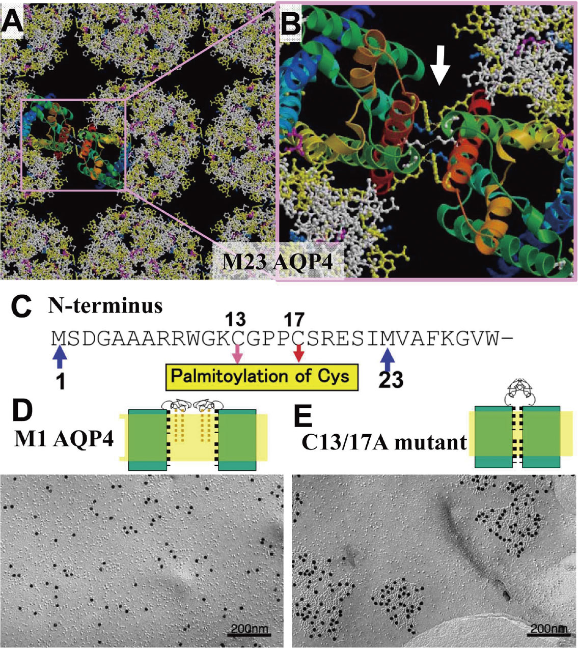
When we speak a language, as a typical example of a human action, our brains consume oxygen and glucose, and the temperature rises at an active local area. Different languages may activate different local areas in the brain. Therefore, regulation of these various conditions in the brain is important for the neural activities and functions, and AQP4 molecules coincidentally show characteristic expression patterns in the brain, especially in the endfeet of astrocytes, ependymal cells, and glial lamellae of the hypothalamus. At the endfeet of astrocytes, crystalline arrays called “orthogonal arrays” were observed long ago, which were later confirmed to be AQP4.33) AQP4 has splicing variants and the short isoform, which starts from the 23rd methionine, AQP4M23, produces large orthogonal arrays, whereas the long isoform starting from AQP4M1 disrupts the array and never yields large orthogonal arrays. Structural analysis of the 2D-crystal by electron crystallography revealed the same orthogonal array lattice constant of 69 Å as observed in intact cells. Our structure provides a basis for explaining the orthogonal array forming intermolecular interactions (Fig. 7A, B). The mechanism underlying the disruption of the arrays by 22 amino acid residues at the N-terminus (Fig. 7C), however, was unclear, even when the structure was carefully observed. The array formation and disruption were then observed in Chinese hamster ovary (CHO) cell membranes by deleting the amino acids one by one from the N-terminus end using the freeze-fracture method. Sodium-dodecyl sulfate-digested freeze fracture replica labeling was performed as described previously34) with small modifications. When the 17th amino acid, a cysteine residue, was deleted, large arrays were suddenly observed. The cysteine residues at positions 13 and 17 of AQP4M1 are conserved in homologs from different species. To verify the possible involvement of Cys13 and/or Cys17 in interfering with the formation of square arrays, we generated AQP4M1 mutants, in which either one or both cysteine residues were mutated to alanine residues. CHO cells transfected with these mutant constructs were analyzed by sodium-dodecyl sulfate-freeze fracture replica labeling. Electron microscopy showed that the single cysteine mutant AQP4M1/C13A formed no square arrays, while the other single cysteine mutant, AQP4M1/C17A, formed a few small arrays. By contrast, the double cysteine mutant, AQP4M1/C13,17A, formed many and large square arrays (Fig. 7D, E). These findings indicate that the presence of even one of the two cysteine residues is sufficient to disrupt the formation of square arrays. Cysteine residues can serve as sites for posttranslational modifications by fatty acids. Our chemical analyses revealed that both Cys13 and Cys17 of AQP4M1 expressed in CHO cells are palmitoylated.35) Palmitoylation of these cysteine residues was confirmed and the lipid modification of even one cysteine was confirmed to disrupt the formation of arrays in AQP4. Without any lipid modification, interactions of tetramers form the orthogonal arrays but a lipid modified amino terminus hinders the array-forming interaction (Fig. 7D, E). Therefore, a longer isoform with cysteine residues cannot form orthogonal arrays, while a shorter isoform without cysteine residues forms large orthogonal arrays.
Our double-layered crystal structure showed an adhesive homophilic interaction of AQP4 molecules (Fig. 8A). Although this may represent the cell adhesive function of AQP4 molecules in vivo, it is possible that this adhesive interaction of AQP4 artificially occurs in the crystal. We therefore confirmed the adhesive function of AQP4 in L-cells expressing no endogenous cell adhesive molecules. Whereas AQP1 showed no cell adhesion, AQP4 was confirmed to have a weak cell adhesive function (Fig. 8B). Interestingly, the arrangement of the channel’s upper and lower layers is not straight but shifted, i.e., staggered (Fig. 8C), and the adhesive interaction between 310 helices is also rather weak. Therefore, water permeation through AQP4 channels could separate the adhesive membranes. The movement could act as an osmotic pressure sensor (Fig. 8D, E). Actually, large numbers of AQP4 molecules are expressed in the glial lamellae of the hypothalamus, which has important osmo-, thermo-, and glucose-sensory brain functions. AQP4 is involved in cerebral edema, multiple sclerosis, neuromyelitis optica, and bipolar disorder.30) Large amounts of AQP4 molecules are expressed in the brains of patients with bipolar disorder.36) How this multifunctional water channel is involved in such higher order cerebral dysfunctions, however, remains unclear. To better understand the protein functions, we attempted to analyze knockout mice. Simple AQP4 knockout mice, however, show no significant phenotype other than reduced edema. As a typical example, the structure of the glial lamellae of simple knockout mice is similar to that in wild-type mice. Therefore, based on the structural analysis of AQP4, we produced genetically modified mice expressing mutant AQP4 without the 310 helix to elucidate the physiological adhesive functions of the water channel. The phenotypes of these mice should prove to be very interesting once they are fully studied.

Adhennels
Channels are central players in many systems, including the central nervous system, and cell adhesion is also a very important function in biological systems. Molecules that acquire these two important functions could regulate physiologically complex and key functions. Therefore, multifunctional channels with cell adhesive functions likely have very important biological functions. We termed this type of molecule “adhennel” by concatenating the two words adhesive and channel. Adhennel family channels are able to regulate more complex functions than ordinary molecules and this might be why AQP4, which has a cell adhesive function together with a water permeable channel, is involved in higher-order cerebral functions. We are interested in two other types of cell adhesive channels, gap junction and tight junction channels.
Gap junction channels.
Gap junction channels have essential roles in many biologically important processes, including cardiac development, fertility, immunity, and electrical signaling in the nervous system. Gap junction channels in electrical synapses regulate rapid ion permeation, for example, the extremely rapid escape response of the crayfish relies on gap junction channels. These channels also allow large solutes to permeate, such as metabolites, nucleotides, and peptides up to 1 kD in size. Cells require regulation of the channel function suitable for cell communications by multiple autonomous gating mechanisms. Therefore, structural analysis of gap junction channels, which are formed by connexin family proteins, was eagerly anticipated.
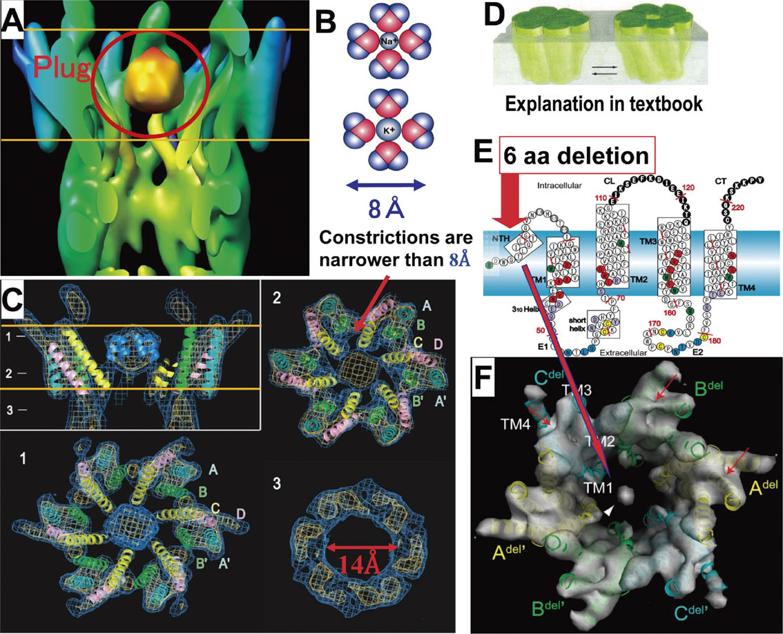
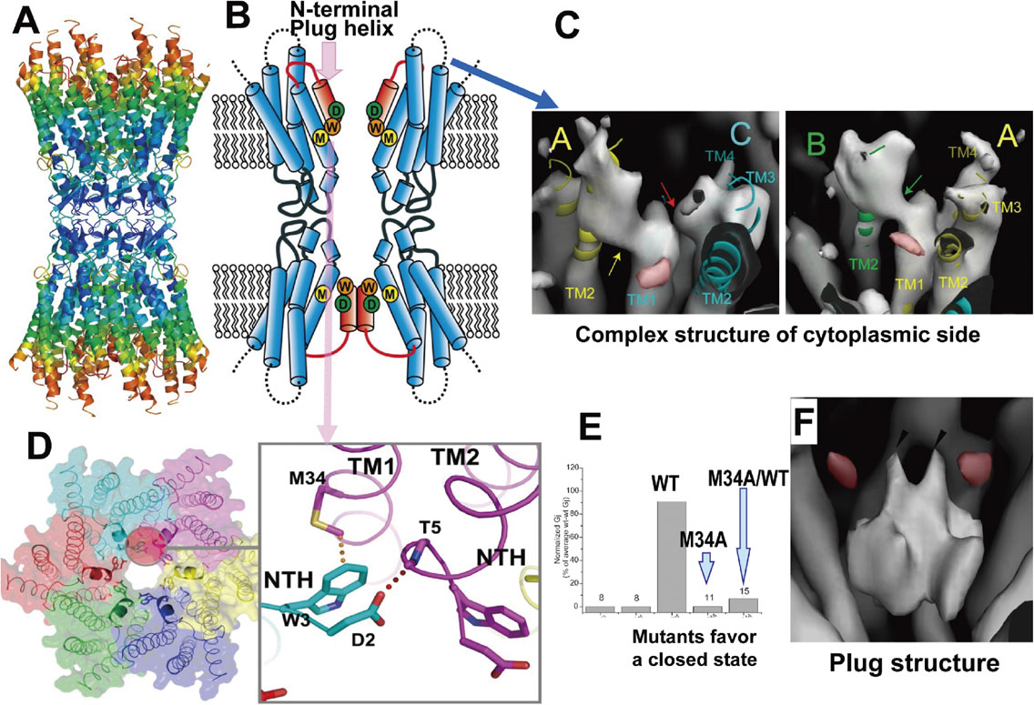
To analyze the closed state structure of a gap junction channel, an M34A mutant of connexin-26, which is related to hearing loss, was expressed in Sf9 cells and its structure was analyzed by electron crystallography. The structure revealed interesting features of the gap junction channels, especially a characteristic density in the channel center at the transmembrane layer.37) We called this density a “plug” (Fig. 9A). Because of the plug, the size of the constriction at the plug part of the channel is narrower than 8 Å and no hydrated ions can pass through, even though the channel diameter of the gap junction channel is up to 14 Å (Fig. 9B, C). The plug is suggested to be formed by N-terminal helices because the N-terminus deletion mutant has a dramatically reduced plug density, and while these data might not support the subunit tilting model for gating, they might support the plug gating model (Fig. 9D, E, F). The structure of wild-type connexin-26 was analyzed by X-ray crystallography.38) Detailed analysis of the structure of the adhesive part revealed that the area is not formed by simple β-sheets but is a rather complex structure (Fig. 10A, B). The amino-terminal helices constructing the plug form a funnel structure in the open conformation, as shown in the upper hemi-channel of Fig. 10B. The interaction between tryptophan 3 in the N-terminal short helix and methionine 34 in helix 1 of the adjacent subunit keeps the N-terminal helix in the open position (Fig. 10D). This structure shows that the M34A mutant specifically favors the closed state, eliminating the interaction between tryptophan 3 and methionine 34 (Fig. 10D, E). This X-ray structure of wild-type connexin-26 could not explain the multiple gating mechanism of gap junction channels, because the cytoplasmic side was very mobile and showed very high temperature factors (shown in red), presumably because the cytoplasmic side is critically deformed by intermolecular interactions in 3D-crystals (Fig. 10A). On the other hand, in 2D-crystals, which are formed by three membrane layers, the complex structure of the cytoplasmic parts in the central membrane layer is protected by the outer layers in 2D-crystals and could be analyzed by electron crystallography39) (Fig. 10C). The resolution of the structure is not sufficient to make an atomic model of connexin-26. Nevertheless, the plug density shows an interesting feature of a double-layered configuration with two small protrusions on the top and four on the lateral face, which gives rise to the up-down arrangement of the six plug helices (Fig. 10F). Then, the movement of even one or two of the helices can allow ions to permeate and might be suitable for fast gating for ions, and the movement of all six helices, which could be regulated by cytoplasmic conformation changes, could allow large solutes to permeate.
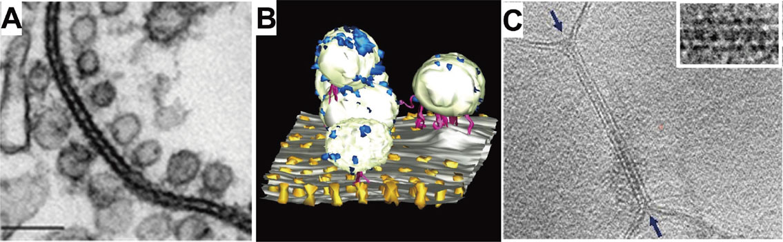
Together with high-resolution structural analysis of the components in the gap junction, a 3D-structure of the gap junction array could also ideally be analyzed. Using electron tomography of negatively-stained ultrathin section of a gap junction, we analyzed the 3D-structure of an innexin-gap junction in the crayfish lateral giant fiber. In the tomographic images, we observed interesting arrangements of vesicles connected to innexin channels as shown in the 3D-representation of the lateral giant fiber40) (Fig. 11A, B). While these tomographic structures provide important structural information of the gap junction system, fixation and staining inevitably limit the resolution as well as the structural information. For analysis of tomographic images without chemical fixation and staining, we developed the 7th generation cryo-EM with a top-entry type helium tilting stage, which allowed us to observe 3D-structures by resolving the lipid bilayer of a fragment of the gap junction prepared from rat forebrain (Fig. 11C). This slice representation of the 3D gap junction structure shows the lipid bilayers of the gap junction and also some complex densities that might be related to the gap junction channels. The resolution must be improved further, however, for clear structural analyses of gap junction channels. Therefore, we began to develop an 8th generation cryo-EM, with which we will analyze structures of membrane proteins in the membrane by using the IBSA method. We are developing the IBSA method together with the 8th generation cryo-EM.
Like gap junctions (GJ in Fig. 12A), tight junctions (TJs in Fig. 12A) are very important adhennel family members. An important function of the tight junctions is the formation of a cell adhesion barrier in epithelial cell sheets that separates the internal spaces from the external spaces, and some tight junctions also contain a paracellular channel function that regulates the flow of ions and solutes between these intercellular spaces (Fig. 12A). Tight junctions comprise a meshwork of linear strands, as shown in the freeze-fracture shadowing image in Fig. 12A. The tight junction strands are predominantly formed by claudins, a family of four-transmembrane proteins (Fig. 12B) with 27 members in humans and mouse. Tsukita’s group discovered claudin molecules in 1998 and confirmed that claudins are the key molecules in tight junctions.41) The physiological properties of tight junctions mainly depend on the specific subtypes of claudins they contain.

We analyzed the structure of claudin-15 by X-ray crystallography and revealed that the transmembrane segments form a tight left-handed four-helix bundle and two extracellular loops form a characteristic β-structure42) (Fig. 12C). The parts of the first and second extracellular segments named ECS1 and ECS2, respectively, form a domain with a unique β-sheet fold (Fig. 12D). Because of the characteristic β-sheet structure of these extracellular loops, we renamed the extracellular loops (ECL) from ECL1 and 2 to extracellular segments (ECS) ECS1 and 2. At the extracellular side, one short helix named extracellular helix (ECH) is observed connecting to the transmembrane helix 2 (TM2; Fig. 12C, F). Five extracellular β-strands that form on ECS1 and 2, called β1, β2, β3, β4, and β5, form a ‘palm’-shaped structure (Fig. 12E). The residues of the conserved W-L-W sequences are located close to each other near the extracellular membrane surface and are embedded in a crevice formed by the top of the four-helix bundle (Fig. 12C). The conserved sequence stabilizes the palm angle to the membrane surface. Another conserved C-C residue stabilizes the β-sheet structure, especially between β3 and β4, by forming a disulfide bond between C52 and C62 (Fig. 12D). In the crystal lattice, the claudin protomers form a linear polymer structure. The tandem intermolecular interactions are mediated by specific regions between adjacent extracellular domains. In particular, a conserved hydrophobic residue protrudes from the ECH in one protomer and snugly fits into a hydrophobic pocket formed by conserved residues in TM3 and ECS2 of the adjacent protomer (Fig. 12F). The two contact surfaces have complementary electrostatic potentials, which are favorable for strand formation.42)
The linear polymer strand has a characteristic feature resembling the teeth of a saw blade (Fig. 13A) and this led us to model the tight junction strand using an antiparallel double row43) (Fig. 13B). In this model, the longest β-strand, β-4, forms an antiparallel β-sheet between the facing protomers and could be energetically favorable. This model is supported by the results of crosslinking experiments of the N61C mutant, because only the N61C mutant can form disulfide bonds between substituted cysteine residues, strongly suggesting the amino acid residue Asn61 is located in closest proximity in the antiparallel β-4 strands. We measured the diameters of the rotary-shadow images of the freeze-fracture samples of tight junctions. Their averaged diameter was 100 Å, nicely fitting the width of the double row model of 60 Å, taking into account the metal shadow thickness of 20 Å.43) The double row structure showed a half-pipe construction on the extracellular surface, as shown in Fig. 12C and also by the dotted lines in Fig. 13A and B. The paracellular channel formed by claudin-15 with acidic residues in the extracellular domain, as shown on the negative surface of the palm model (Fig. 13D), allows Na+ ions to permeate, and the claudin-10a channel with positive residues (Fig. 13E) allows the permeation of Cl− ions. The association with antiparallel claudin double rows in the adjoining membrane would result in extracellular β-barrel-like pores with 20 β-strands that could form paracellular pathways parallel to the membrane plane43) (Fig. 13F, G). The inside of the β-barrel-like pore could effectively be regulated by its surface features related to the size and/or charges of the side chain of the amino acids of the β-sheet, because they protrude almost perpendicular from the pore surface of the β-sheet. We could not determine the atomic coordinates of the disordered part in V1, which could be placed at around the ellipse indicated by V1 in Fig. 13F, whereas the structure at V2 was determined. These parts, V1 and V2, were assigned as valuable regions in 27 subtypes and also form a “pillar” shape by interacting with the same parts of the adjoining V1 and V2 (Fig. 13F, G). Therefore, these parts are very important for determining the pairing of claudins in the 27 subtypes. By constructing 2D-crystals, we would like to analyze the adjoining structure by electron crystallography and confirm the paracellular model of the adhesive tight junction structure. If we are unable to grow 2D-crystals of claudin, however, we plan to use a more powerful method, such as electron tomography, that will allow the complex 3D-structure to be analyzed without crystallization.

Because the drugs used to treat brain diseases must reach inside the brain, the blood brain barrier must be regulated for effective drug delivery into the brain. The blood brain barrier is formed by claudins, and claudin-5 knockout in mice changes the permeability of the blood brain barrier even to a primary amine-reactive biotinylation reagent.44) Immunofluorescence microscopy of SF-7 cells demonstrated that stable expression of claudin-19 allows these cells to form tight junctions. We also confirmed that the C-terminal domain of Clostridium perfringens enterotoxin (C-CPE) disassembles the tight junctions. We then analyzed the structure of claudin-19 in complex with C-CPE.45) CPE was thought to bind with only ECS2, but the analyzed structure revealed that C-CPE binds both ECS2 and ECS1. We therefore evaluated whether these interactions were meaningful in physiological conditions by creating mutants in which the interacting residues were changed one-by-one on claudin-19 and analyzing the effect on complex formation between each claudin-19 mutant and C-CPE. The binding parts were all consistent with the structurally revealed interacting residues, thus strongly supporting the physiological relevance of the binding structure. As shown in Fig. 12F, a tight junction strand formed by the conserved hydrophobic residue that protrudes from the ECH in one protomer fits snugly into the hydrophobic pocket formed by TM3 and ECS2 in the adjacent protomer (Fig. 14A). By binding C-CPE, the parts indicated by the dotted arrowheads in Fig. 14B are disordered and the tight junction strand is disassembled45) (Fig. 14). The mechanism of the disruption of tight junctions by C-CPE might provide clues to the regulation of the blood brain barrier and will facilitate the development of a drug delivery system that permeates the blood brain barrier.

Future prospects of structural physiology
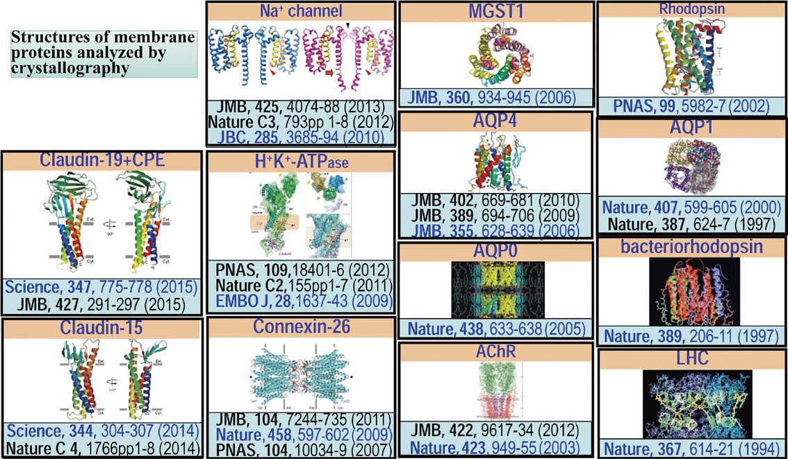
To elucidate the structure and function of membrane proteins, we analyzed their structures, as shown in Fig. 15, based on crystallography, including electron crystallography utilizing the originally developed cryo-EMs (Fig. 1). Analyses of these structures at such a detailed level are the bases of the field of structural physiology. Gaining sufficient insight into brain functions and other biological functions will require molecular-level structural analyses of research targets and structures in different functional states. Structural analyses based on crystallography naturally requires the crystallization of proteins and/or their functional complexes, but crystallization is generally difficult or requires a rather long time — years in the case of membrane proteins. For a detailed understanding of the dynamic functions of proteins, at least a few structures must be analyzed in different states. Conformational changes of proteins will destroy the crystals or deteriorate their crystallinity. These obstacles might deter researchers from attempting structural studies of their targets of interest. Nevertheless, the field of structural biology has recently undergone dramatic changes due to advancements in single particle analysis based on cryo-EM. For example, Cheng’s group analyzed the structure of TRP channels by single particle analysis.18),46) Although many crystallographers had attempted to analyze TRP channels, no one had previously succeeded in analyzing their structures. Therefore, successful structural analysis of TRP channels has had a strong impact in the field. Recent structural analysis of β-galactosidase at 2.2 Å resolution using this method has also had a strong impact.47) The innovative changes are mainly attributed to the development of a direct electron detector, the K2 Summit, which was developed by Gatan as shown in Cheng’s paper.48) Already several structures have been analyzed using this detector, which is changing the field of structural biology. Single particle analysis requires rather large particles, proteins, or protein complexes, for high-resolution structural analysis, as Henderson predicted.49) Therefore, the production of an antibody-recognizing structure and ideally fixing a particular conformation might be key for expanding high-resolution structural analyses by single particle analysis.
As discussed in the section “Structure and function of water channels”, the structure of a membrane protein must be analyzed in the membrane to gain an understanding of its physiological function. For structural analysis by the single particle method, membrane proteins are suspended in a detergent- or amphipol-solubilized condition, whereas electron crystallography using 2D-crystals can reveal the structure in the membrane that mimics the natural environment. Therefore, we will use electron crystallography to analyze the structure of membrane proteins. Together with electron crystallography improvement trials, we are developing a new method, termed IBSA, by which we can analyze the structure of membrane proteins in the membrane by a method similar to single particle analysis without crystals. Usually, membrane proteins are purified after they have been solubilized in detergent and then reconstituted into a lipid bilayer. IBSA will allow for analysis of the structure of membrane proteins without even a purification process, although this analysis is more challenging and difficult. If antibodies for target proteins are produced, structural analysis could be facilitated by IBSA even when the protein molecules are not detergent-purified. A low-dose image of membranes containing the target protein molecules is obtained under a tilting condition and then a high dose image of the same specimen area in an untilted condition is obtained in a highly defocused condition, providing a higher contrast image. The high-contrast untilted high-dose image helps to classify the low-dose images of the target molecules. If the images can be successfully classified, we will be able to analyze 3D structures of membrane proteins in the membrane.
The speed of recent structural analyses of membrane proteins is almost an order of magnitude greater than that achieved a decade ago, even with crystallography, for several reasons. The dramatic changes in the electron microscopic field caused by the direct electron detector have accelerated the speed of structural analyses. Additional technological and methodological advancements will dramatically change the field of structural physiology, further enhancing its importance and attractiveness to researchers. I am personally interested in the structural physiology of “adhennels”, such as water channels, gap junction channels, tight junctions, and voltage-sensitive ion channels with cell adhesive functions, which may be related to neural network formation. Methodological developments such as IBSA together with instrumental development of the 8th generation cryo-EM (Fig. 1) will extend the possibilities of obtaining high-resolution information from increasingly complex protein-lipid structures, including adhennels, and structural physiology will become an important research field for basic as well as applied biology, such as drug development.
Profile

Yoshinori Fujiyoshi was born in Gifu, Japan, in 1948, and graduated from the Faculty of Science, Nagoya University in 1971. He received his Ph.D. from Kyoto University in 1982. In 1980, he began working as a Research Assistant at the Institute for Chemical Research, Kyoto University. He then moved to the Protein Engineering Research Institute as a Senior Research Scientist and Research Director in 1987 and 1988, respectively. After 1994, he was the Research Director at the International Institute for Advanced Research, Matsushita Electric Industrial Co., Ltd. In 1996, he became a Professor at the Graduate School of Science, Kyoto University. He then moved to Nagoya University in 2012. By developing cryo-electron microscopes, he has focused his efforts on the detailed analysis of the structures of membrane proteins, such as water channels, ion channels, receptors, gap junction channels, and tight junctions, to better understand their physiological functions. The development of electron crystallography, cryo-electron tomography and real-space averaging methods together with continued instrument development will extend the ability of obtaining high-resolution information from increasingly complex protein-lipid structures and living organisms.
Acknowledgements
These studies were performed in collaboration with many researchers whose names are recorded as authors in each referenced paper, and I am grateful to each and all of these collaborators. This work was supported by Grants-in-Aid for Scientific Research (S) and the Japan New Energy and Industrial Technology Development Organization (NEDO), and also Japan Agency for Medical Research and Development (AMED).
References
- 1) Declan, A.D., Cabral, J.H.M., Pfuetzner, R.A., Kuo, A., Gulbis, J.M., Cohen, S.L., Chait, B.T. and MacKinnon, R. (1998) Structure of the potassium channel: molecular basis of K+ conduction and selectivity. Science 280, 69–77.
- 2) Cabral, J.H.M., Zhou, Y. and MacKinnon, R. (2001) Energetic optimization of ion conduction rate by the K+ selectivity filter. Nature 414, 37–42.
- 3) Zhou, Y., Cabral, J.H.M., Kaufman, A. and MacKinnon, R. (2001) Chemistry of ion coordination and hydration revealed by a K+ channel-Fab complex at 2.0 Å resolution. Nature 414, 43–48.
- 4) Jiang, Y., Ruta, V., Chen, J., Lee, A. and MacKinnon, R. (2003) The principle of gating charge movement in a voltage-dependent K+ channel. Nature 423, 42–48.
- 5) Long, S.B.L., Tao, X., Campbell, E.B. and MacKinnon, R. (2007) Atomic structure of a voltage-dependent K+ channel in a lipid membrane-like environment. Nature 450, 376–382.
- 6) Walz, T., Hirai, T., Murata, K., Heymann, J.B., Mitsuoka, K., Fujiyoshi, Y., Smith, B.L., Agre, P. and Engel, A. (1997) Three-dimensional structure of aquaporin 1. Nature 287, 624–627.
- 7) Murata, K., Mitsuoka, K., Hirai, T., Walz, T., Agre, P., Heymann, J.B., Engel, A. and Fujiyoshi, Y. (2000) Structural determinants of water permeation through aquaporin-1. Nature 407, 599–605.
- 8) Gonen, T., Cheng, Y., Sliz, P., Hiroaki, Y., Fujiyoshi, Y., Harrison, S.C. and Walz, T. (2005) Lipid-protein interactions in double-layered two-dimensional AQP0 crystals. Nature 438, 633–638.
- 9) Hiroaki, Y., Tani, K., Kamegawa, A., Gyobu, N., Nishikawa, K., Suzuki, H., Walz, T., Sasaki, S., Mitsuoka, K., Kimura, K., Mizoguchi, A. and Fujiyoshi, Y. (2006) Implications of the aquaporin-4 structure on Array formation and cell adhesion. J. Mol. Biol. 355, 628–639.
- 10) Suzuki, H., Nishikawa, K., Hiroaki, Y. and Fujiyoshi, Y. (2008) Formation of aquaporin-4 arrays is inhibited by palmitoylation of N-terminal cysteine residues. Biochim. Biophys. Acta 1778, 1181–1189.
- 11) Uyeda, N., Kobayashi, T., Ishizuka, K. and Fujiyoshi, Y. (1979) High voltage electron microscopy for image discrimination of constituent atoms in crystals and molecules. Chem. Scr. 14, 47–61.
- 12) Uyeda, N., Kobayashi, T., Ishizuka, K. and Fujiyoshi, Y. (1980) Crystal structure of Ag-TCNQ. Nature 285, 95–97.
- 13) Abe, K., Tani, K., Nishizawa, T. and Fujiyoshi, Y. (2009) Inter-subunit interaction of gastric H+,K+-ATPase prevents reverse reaction of the transport cycle. EMBO J. 28, 1637–1643.
- 14) Unwin, N. (1995) Acetylcholine receptor channel imaged in the open state. Nature 373, 37–43.
- 15) Miyazawa, A., Fujiyoshi, Y. and Unwin, N. (2003) Structure and gating mechanism of the acetylcholine receptor pore. Nature 423, 949–955.
- 16) Unwin, N. and Fujiyoshi, Y. (2012) Gating movement of acetylcholine receptor caught by plunge-freezing. J. Mol. Biol. 422, 617–634.
- 17) Henderson, R. and Unwin, P.N.T. (1975) Three-dimensional model of purple membrane obtained by electron microscopy. Nature 257, 28–32.
- 18) Liao, M., Cao, E., Julius, D. and Cheng, Y. (2013) Structure of TRPV1 ion channel determined by electron cryo-microscopy. Nature 504, 107–112.
- 19) Adrian, M., Dubochet, J., Lepault, J. and McDwall, A.W. (1984) Cryo-electron microscopy of viruses. Nature 308, 32–36.
- 20) Fujiyoshi, Y., Mizusaki, T., Morikawa, K., Yamagishi, H., Aoki, Y., Kihara, H. and Harada, Y. (1991) Development of a superfluid helium stage for high-resolution electron microscopy. Ultramicroscopy 38, 241–251.
- 21) Fujiyoshi, Y. (1998) The structural study of membrane proteins by electron crystallography. Adv. Biophys. 35, 25–80.
- 22) Hirai, T., Murata, K., Mitsuoka, K., Kimura, Y. and Fujiyoshi, Y. (1999) Trehalose embedding technique for high-resolution electron crystallography. J. Electron Microsc. (Tokyo) 48, 653–658.
- 23) Gonen, T., Cheng, Y., Sliz, P., Hiroaki, Y., Fujiyoshi, Y., Harrison, S.C. and Walz, T. (2005) Lipid-protein interactions in double-layered two-dimensional AQP0 crystals. Nature 438, 633–638.
- 24) Kimura, Y., Vassylyev, D.G., Miyazawa, A., Kidera, A., Matsushima, M., Mitsuoka, K., Murata, K., Hirai, T. and Fujiyoshi, Y. (1997) Surface of bacteriorhodopsin revealed by high-resolution electron crystallography. Nature 389, 206–211.
- 25) Kuehlbrandt, W., Wang, D.N. and Fujiyoshi, Y. (1994) Atomic model of plant light-harvesting complex by electron crystallography. Nature 367, 614–621.
- 26) Sato, C., Ueno, Y., Asai, K., Takahashi, K., Sato, M., Engel, A. and Fujiyoshi, Y. (2001) The voltage-sensitive sodium channel is a bell-shaped molecule with several cavities. Nature 409, 1047–1051.
- 27) Payandeh, J., Scheuer, T., Zheng, N. and Catterall, W.A. (2011) The crystal structure of a voltage-gated sodium channel. Nature 475, 353–357.
- 28) Tsai, C.J., Tani, K., Irie, K., Hiroaki, Y., Shimomura, T., McMillan, D.G., Cook, G.M., Schertler, G., Fujiyoshi, Y. and Li, X.D. (2013) Two alternative conformations of voltage-gated sodium channel. J. Mol. Biol. 425, 4074–4088.
- 29) Irie, K., Kitagawa, K., Nagura, H., Imai, T., Shimomura, T. and Fujiyoshi, Y. (2010) Comparative study of the gating motif and C-type inactivation in prokaryotic voltage-gated sodium channels. J. Biol. Chem. 285, 3685–3694.
- 30) Agre, P., King, L.S., Yasui, M., Guggino, W.B., Ottersen, O.P., Fujiyoshi, Y., Engel, A. and Nielsen, S. (2002) Aquaporin water channels-from atomic structure to clinical medicine. J. Physiol. 542, 3–16.
- 31) Ho, J.D., Yeh, R., Sandstrom, A., Chormy, I., Harries, W.E.C., Robbins, R.A., Miercke, L.J.W. and Stroud, R.M. (2009) Crystal structure of human aquaporin 4 at 1.8 Å and its mechanism of conductance. Proc. Natl. Acad. Sci. U.S.A. 106, 7437–7442.
- 32) Sengpta, D., Behera, R.N., Smith, J.C. and Ullmann, G.M. (2005) The α helix dipole: screened out. Structure 13, 849–855.
- 33) Rash, J.E., Yasumura, T., Hudson, C.S., Agre, P. and Nielsen, S. (1998) Direct immunogold labeling of aquaporin-4 in square arrays of astrocyte and ependymocyte plasma membranes in the rat brain and spinal cord. Proc. Natl. Acad. Sci. U.S.A. 95, 11981–11986.
- 34) Fujimoto, K. (1997) SDS-digested freeze-fracture replica labeling electron microscopy to study the two-dimensional distribution of integral membrane proteins and phospholipids in biomembranes: practical procedure, interpretation and application. Histochem. Cell Biol. 107, 87–96.
- 35) Suzuki, H., Nishikawa, K., Hiroaki, Y. and Fujiyoshi, Y. (2008) Formation of aquaporin-4 arrays is inhibited by palmitoylation of N-terminal cysteine residues. Biochim. Biophys. Acta 1778, 1181–1189.
- 36) Iwamoto, K., Kakiuchi, C., Bundo, M., Ikeda, K. and Kato, T. (2004) Molecular characterization of bipolar disorder by comparing gene expression profiles of postmortem brains of major mental disorders. Mol. Psychiatry 9, 406–416.
- 37) Oshima, A., Tani, K., Hiroaki, Y., Fujiyoshi, Y. and Sosinsky, G.E. (2007) Three-dimensional structure of a human connexin26 gap junction channel reveals a plug in the vestibule. Proc. Natl. Acad. Sci. U.S.A. 104, 10034–10039.
- 38) Maeda, S., Nakagawa, S., Suga, M., Yamashita, E., Oshima, A., Fujiyoshi, Y. and Tsukihara, T. (2009) Structure of the connexin-26 gap junction channel at 3.5 Å resolution. Nature 458, 597–602.
- 39) Oshima, A., Tani, K., Toloue, M.M., Hiroaki, Y., Smock, A., Inukai, S., Cone, A., Nicholson, B.J., Sosinsky, G.E. and Fujiyoshi, Y. (2011) Asymmetric configurations and N-terminal rearrangements in connexin26 gap junction channels. J. Mol. Biol. 405, 724–735.
- 40) Ohta, Y., Nishikawa, K., Hiroaki, Y. and Fujiyoshi, Y. (2011) Electron tomographic analysis of gap junctions in the lateral giant fibers of crayfish. J. Struct. Biol. 175, 49–61.
- 41) Furuse, M., Fujita, K., Hiiragi, T., Fujimoto, K. and Tsukita, S. (1998) Claudin-1 and -2: novel integral membrane proteins localizing at tight junctions with no sequence similarity to occludin. J. Cell Biol. 141, 1539–1550.
- 42) Suzuki, H., Nishizawa, T., Tani, K., Yamazaki, Y., Tamura, A., Ishitani, R., Domae, N., Tsukita, S., Nureki, O. and Fujiyoshi, Y. (2014) Crystal structure of a claudin provides insight into the architecture of tight junctions. Science 344, 304–307.
- 43) Suzuki, H., Tani, K., Tamura, A., Tsukita, S. and Fujiyoshi, Y. (2015) Model for the architecture of claudin-based paracellular ion channels through tight junctions. J. Mol. Biol. 427, 291–297.
- 44) Nitta, T., Hata, M., Gotoh, S., Seo, Y., Sasaki, H., Furuse, M. and Tsukita, S. (2003) Size-selective loosening of the blood-brain harrier in claudin-5-deficient mice. J. Cell Biol. 161, 653–660.
- 45) Saitoh, Y., Suzuki, H., Tani, K., Nishikawa, K., Irie, K., Ogura, Y., Tamura, A., Tsuchita, S. and Fujiyoshi, Y. (2015) Structural insight into tight junction disassembly by Clostridium perfringens enterotoxin. Science 347, 775–778.
- 46) Paulsen, C., Armache, J.P., Gao, Y., Cheng, Y. and Julius, D. (2015) Structure of the TRPA1 ion channel suggests regulatory mechanisms. Nature 520, 511–517.
- 47) Bartesaghi, A., Merk, A., Banerjee, S., Matthies, D., Wu, X., Milne, J.L.S. and Subramaniam, S. (2015) 2.2 Å resolution cryo-EM structure of b-galactosidase in complex with a cell-permeant inhibitor. Science 348, 1147–1151.
- 48) Li, X., Mooney, P., Zheng, S., Booth, C.R., Braunfeld, M.B., Gubbens, S., Agard, D.A. and Cheng, Y. (2013) Electron counting and beam-induced motion correction enable near-atomic-resolution single-particle cryo-EM. Nat. Methods 10, 584–590.
- 49) Henderson, R. (1995) The potential and limitations of neutrons, electrons and X-rays for atomic resolution microscopy of unstained biological molecules. Q. Rev. Biophys. 28, 171–193.