Abstract
Cosmic-ray muons (CRM) arriving from the sky on the surface of the earth are now known to be used as radiography purposes to explore the inner-structure of large-scale objects and landforms, ranging in thickness from meter to kilometers scale, such as volcanic mountains, blast furnaces, nuclear reactors etc. At the same time, by using muons produced by compact accelerators (CAM), advanced radiography can be realized for objects with a thickness in the sub-millimeter to meter range, with additional exploration capability such as element identification and bio-chemical analysis. In the present report, principles, methods and specific research examples of CRM transmission radiography are summarized after which, principles, methods and perspective views of the future CAM radiography are described.
1. Introduction; CRM and CAM radiography
Major constituents of elementary particles, under the frame work of the standard model of particle physics, are known to be leptons and quarks, where in the leptons, major particles are electrons, muons and neutrinos. In this report, we would like to restrict ourselves to the muons, which usually do not exist as long-lived stable particles but are produced by particle-accelerators and/or cosmic-rays, and application of the muons to radiography (Roentgen photography).
There are two species of muon: positively charged μ+ and negatively charged μ−. The lifetime in vacuum is 2.2 µs with a relativistic correction for the high energy in-flight muons such as CRM. For the muon stopping inside the matter, life time of the μ− becomes shorter due to the increase of nuclear capture probability. The masses of both the μ+ and μ− are 1/9 of proton mass and 207 times electron mass. Energetic muons higher than GeV can be obtained as CRM with weak intensity, while intense muons below some 100 MeV can be obtained with strong intensity by hadron accelerators, as summarized in Fig. 1a. A variety of scientific researches has been conducted by using these two types of muons including radiography.1)

For the application of muons to radiography, the following property of the muon is the most important. Since the muons are interacting with the surrounding atoms and molecules mainly via electromagnetic interactions and not via strong interactions, muons have a high penetration capability so that by selecting the kinetic energy value, a stopping range can be uniquely identified from nanometer to kilometer scale, as shown in the case of Cu in Fig. 1b.
In general, by increasing energy of charged particles, the stopping range increases. However, for protons, when their kinetic energies are beyond the 10 MeV range, they are converted into other nucleons or nuclei through nuclear forces via strong interactions. Additionally, electrons with the energy being above 1 MeV, because of their light mass, are converted into photons.
Thus, in order to probe inner structure of a substance, whose thickness is more than some critical length; e.g. more than 1 m water, more than 30 cm Carbon and more than 10 cm Fe, particle of muon is only capable to be able to penetrate and produce an appearance signal non-destructively at the detectors placed outside the substance.1)
By employing the CRM which has a fairly wide and large energy spectrum, ranging 100 MeV to 100 GeV and the CAM with an energy range from keV to 100 MeV, one can cover all the energy range shown in Figs. 1a and 1b. By varying the energy from keV to 100 GeV, stopping range can be controlled from nanometer to kilometer scale. As described later, because the CAM is an artificial product, it has unique properties such as polarization control, timing control, spatial positioning control etc.
More than 50 years ago, concepts of compact accelerators at the level of some 10 MeV were considered and some of them were industrially produced and used. These are mainly compact sources of either fast neutrons or photons for medical use and/or industrial application. It had been considered for a long time that producing muons was difficult, time-consuming and expensive work, which requires a large-scale installation of accelerators in the range of a few hundred Mega-eV and associated accelerator facilities. Recently, because of the technological development of the accelerator producing industry, it has become possible to consider and construct movable accelerators including radiation shielding. These include, for example, accelerators that produce electrons and/or protons at greater than 250 MeV, which are, at the same time, capable of pion/muon production.
Along this line, recently, some urgent requirements of compact accelerator systems have become more attractive because social needs have been grown for the subjects other than muon science applications. Representative examples are as follows: a) for radiation cancer therapy using 250 MeV protons, a compact accelerator that can be accommodated as a part of singe treatment room is required; b) a 300 MeV electron linear accelerator (linac) of synchrotron radiation source is now required to be movable, with planned application to instrumentation for industrial inspections. Both accelerators are marginally produce pion/muon beam.
The popularity of these compact accelerators is a motivation of the later part of the present paper, mainly because the energy ranges of these accelerators are marginally above the threshold of the pion/muon production.
However, even after approval of usefulness of the compact 300 MeV electron accelerators and/or 250 MeV proton accelerators for pion/muon production, there is another difficulty for a realization of the advanced muon radiography. As described later in detail, pions produced by electrons/protons have large angular and energy spreads. Moreover, kinematics of pion-to-muon decay does increase such randomness in muon beam. In order to realize the advanced transmission muon radiography, as described later in detail, it is important to have a monochromatic and straight muon beam. In order to convert the muon beam from a nearly random beam to an advanced delicate beam, a special technique is required to make a drastic improvement of the beam. For this purpose, at the end of the present report we would like to propose the following techniques; a) zero-energy cooling of the accelerator producing muons and b) re-acceleration of the cooled muon beam.
Combining with both CRM and CAM methods, we are able to measure a map of density-length, which is exploring the inner structure of the substance with thickness from sub-micrometer to kilometer range by transmission radiography. In some cases, the element identification can be possible, enabling element selective radiography.
In this report, we would like to take the following presentation scheme. Following the present 1) Introduction, 2) a detailed description of the cosmic-ray muon (CRM) transmission radiography is presented, along with principles and nature of the CRM. Then 3) specific research activities so far realized by the CRM transmission radiography are presented, namely brief summaries of applications for analyzing volcanos, blast furnaces, nuclear reactors, cargo containers and reinforced concrete buildings. Some suggestions for new directions will be presented at the end of each Section. 4) CAM radiography, including presentation of possible accelerators for CAM, followed by the muon beam cooling method for advanced transmission radiography and element selective radiography capability. 5) Concluding remarks for the future of the muon radiography in general and potential realistic prospects of CRM radiography are presented at the end.
2. A detailed description of CRM transmission radiography
Of the two types of muons to be used for radiography (CRM and CAM) to explore the inner-structure of objects, CRM may be used to investigate objects with a thickness beyond the meter scale. Basic properties of the CRM and principles of various methods of the transmission radiography using CRM are described in the followings.
2.1. Source of muons in CRM radiography.
2.1.1 General properties.
The CRM arrive on the surface of the earth, originating from the decay of the pions and kaons which are produced by nuclear interactions between the energetic protons coming from the universe to the earth and the atmospheric nuclei (mainly N and O). The intensity of CRM from the top (zero zenith-angle) is roughly 1/(cm)2/min or 1/(an area of a human palm)/s. More precisely, zenith-angle dependent energy spectrum is known to have a shape as shown in Fig. 2a. There, the corresponding range for the case of rock is also shown.
The zenith-angle dependent energy spectrum shown in Fig. 2a is essentially independent of time and location on the planet. There is a correction of this independence to the % accuracy, accounting for variations in air humidity and for a directional dependence due to earth magnetic field called east-west effect.
In addition to the zenith angle dependent energy spectrum, the CRM (cosmic-ray muons at sea level) are known to have the following properties; a mixed charge state2) (μ+ (0.6) and μ− (0.4)) observed by the charge dependent deflection under magnetic field and a partial spin polarization3) (−0.33 for μ+) observed by the asymmetric positron distribution of the stopping CRM. Due to their high energy nature, a stopping distribution of CRM in the specimens to be investigated extends from a few meters to more than 100 meters as schematically indicated in Fig. 2a for the case of rock.
By placing a large specimen perpendicular to the CRM incoming direction, because of the range-energy relation, transmitted intensity changes as shown in Fig. 2b, where the specimen used is a rock. By increasing thickness (density × geometrical length), transmitted intensity decreases. Conversely, by detecting the decrease of transmitted CRM intensity, the specimen thickness (density length) can be known. When similar measurements are performed for the CRM passages by identifying each track, one can obtain cumulative data for the density map of the specimen. This is the principle of the Intensity Attenuation (IA) type CRM transmission radiography.
As described later, in the majority of the CRM transmission radiography, measurements are done for either intensity attenuation or passage deflection due to multiple scattering of energetic muons (more than 100 MeV) during the passage of the muons. Therefore, neither charge state of the muon (either μ+ or μ−) nor polarization of the muon is effectively involved in the data interpretation to obtain radiography information. However, as shown later, the phenomena which occur after stopping of either CRM show significant effects with strong dependent on both charge state and polarization.
2.1.2 Recent progress in understanding the properties of the CRM at sea-level.
The nucleons in the nuclei, (mainly N and O) of the earth atmosphere at elevation of 10 km are continuously bombarded by the primary cosmic-rays of high-energy charged particles dominantly consisting of protons. During these bombardments, pions and kaons are produced, both of which decay into muons and neutrinos as,
| \begin{equation}
\pi^{\pm}\rightarrow \mu^{\pm} + \overline{\nu_{\mu}}(\nu_{\mu}),\ \sim 100\%
\end{equation}
| [1] |
| \begin{equation}
K^{\pm} \rightarrow \mu^{\pm} + \overline{\nu_{\mu}}(\nu_{\mu}),\ \sim 63.5\%,
\end{equation}
| [2] |
life times at rest of which are 26 and 12 ns, respectively.
Attenuation of CRM transmission intensity through the specimen to be investigated can be known by the intensity of the transmitted CRM with reference to the original incoming CRM intensity, namely the CRM intensity through nothing. As described later, in some case of the measurement geometry, the unperturbed incoming CRM can simultaneously be measured as a Backward (BWD) signal towards the sky. However, in most cases, and particularly for the geometry of the lower zenith angle CRM, the reference data of the unperturbed CRM is difficult to be measured simultaneously. In such cases, the prediction of the unperturbed CRM intensity has to be known through the existing experimental data.
The need for characterization of CRM at the surface of the earth exists not only for the purpose of radiography, but also for background estimation in neutrino experiments. So far, there have been several experiments measuring momentum spectra of CRM intensity at various zenith angles. Presently various existing experimental data can be compiled as follows; name of experiment, zenith angle range (degrees), muon momentum range (GeV). Nandi and Sinha,4) 0–0.3, 5–1200; MARS,5) 0–0.08, 20–500; Kellogg et al.,6) 25.9–34.1/70.9–79.1, 50–1700; OKAYAMA Univ,7) 0–1/26–34/59–61/69–81/79–81, 1.5–250; Kiel-Desy,8) 68–82, 1–1000; MUTRON,9) 86–90, 100–20,000. Some selected data for muon momentum larger than 1 TeV/c (muon range in rock being larger than 225 m) and zenith angle larger than 75 degree is shown in Table 1, which is useful for the imaging of volcano summit.
Table 1. Some published experimental results of differential CRM intensity for muon momentum (
pμ) being lager than 1 TeV/c and zenith angle (
Θz) being lager than 75°, relevant for the imaging of the summit region of volcano
Zenith angle
Momentum
(TeV/c) |
Differential CRM
intensity
(GeV/c·cm2·sr·s)−1 |
Reference and
comment |
| Θz = 75° |
| 1.0 |
2.99(18) × 10−10 |
6). 1.067 TeV |
| 1.0 |
3.982 × 10⁻¹⁰ |
7). 0.99022 TeV |
| Θz = 86° |
| 1.0 |
2.71(5) × 10−10 |
9). 1.000–1.259 TeV |
| 2.0 |
2.97(12) × 10−11 |
9). 1.995–2.512 TeV |
| 5.0 |
1.59(18) × 10−13 |
9). 5.012–6.310 TeV |
| 10.0 |
1.18(33) × 10−13 |
9). 10.000–12.589 TeV |
| 20.0 |
1.10(55) × 10−14 |
9). 19.953–25.119 TeV |
Based upon these experimental observations,4)–9) Reyna has proposed a parametrization of the CRM spectrum10) by the method following several historical works. The following formula was proposed for the CRM intensity of muon momentum (pμ in GeV/c) and zenith angle (θ);
| \begin{equation}
I(p_{\mu},\theta) = \mathit{cos}^{3}(\theta)I_{V}(p_{\mu})
\end{equation}
| [3] |
| \begin{equation*}
I_{V}(p_{\mu}) = c_{1}p_{\mu}{}^{-\xi},
\end{equation*}
|
| \begin{equation*}
\xi = (c_{2} + c_{3}\mathit{log}(p_{\mu}) + c_{4}\mathit{log}^{2}(p_{\mu}) + c_{5}\mathit{log}^{3}(p_{\mu})
\end{equation*}
|
where c
1(0.00253 cm
−2 s
−1 sr
−1 GeV
−1), c
2(0.2455), c
3(1.288), c
4(−0.2555) and c
5(0.0209) are proposed.
Although in IA transmission of CRM, the charge of the muon does not appear, it does appear when the CRM is stopped in the specimens to be investigated. As described later, the μ+ is spin-polarized and producing spin rotation/relaxation data which is useful for chemical analysis of the specimens, while the μ− has nuclear capture capabilities, causing a Z-dependent e− decay life-time which can be used for the element identification. Experimentally, the observed charge ratio for the muon energy 13–200 GeV7) R(μ+/μ−) was found to have a slight zenith angle dependence; 1.335(57) at 0°, 1.241(35) at 38°, 1.275(28) at 45°, 1.224(57) at 52°, 1.237(25) at 59°, 1.246(19) at 67°, 1.254(21) at 75°, 1.266(26) at 80°. The data are summarized in Fig. 3. The reason of R (μ+/μ−) > 1 is mainly coming from the fact that majority of the primary cosmic-ray particles are protons.

Now let us briefly mention azimuthal angular dependence of CRM intensity on the east-west effect. By geomagnetic field effect, total and positive CRM for higher zenith-angle and larger muon momentum are slightly less at east directions, by a factor of less than 10%.7)
2.2 Experimental methods of CRM radiography.
2.2.1 Intensity-attenuation (IA) type CRM transmission radiography.
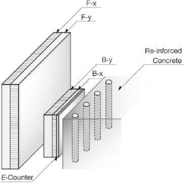
By determining zenith angle and materials of the CRM penetrating object to be examined, the IA (intensity attenuation) of the CRM takes place systematically depending upon material density length (thickness × density) as seen for the case of rock (density = 2.2 g/cm3) and iron (density = 7.8 g/cm3) in Fig. 4. At the same time, because of the charged particle nature, the passage track of the CRM can easily be determined by employing more than 2 vertical planes of position sensitive detectors (PSDs) of the ionization signals of CRM radiation as seen in Fig. 5a. From the cumulative event data of the CRM tracks at the crossing points inside the objective material, a map of density length can be obtained as radiographic data.

By using vertically arriving (zero zenith angle) CRM, inner structure of some rocks and Egyptian Pyramid (the Second Pyramid in Giza)11) had been investigated, where tunnels were prepared right underneath the objective materials to accommodate detection systems. Due to the difficulties associated with tunnel construction, applications to the large-scale industrial and geophysical materials had been limited (almost none). A real breakthrough has been made by employing the use of the near-horizontal CRM.12) In order to realize reliable detection of a weak signal (CRM flux at 90° is almost 1/50 of that at 0°) and a removal of a huge background signals such as the soft components (background at 90° is 20 times larger than that at 0°), the following technical developments have been made.12),13)
1) In order to obtain a reliable long-term measurement of the weak signal of the near-horizontal CRM, it was proposed to detect a simultaneous measurement of FWD IA (through objective material) and BWD IA (through nothing, opposite to objective material and mostly towards open sky) with exactly the same configuration of the detection system. Then, by treating all the data in terms of FWD/BWD, some fluctuations in either geometrical solid-angle or efficiency of the detection system can be either removed or reduced.
2) Strong soft component background signals such as photons, electrons and positrons in near horizontal CRM were found to be removed by placing heavy metals at intermediate position of multiple PSD’s and by detecting multiply produced charged particles which are mostly produced by the soft component at the heavy metal plates.
Through these achievements, non-invasive inner structure probing of the large geophysical and industrial objects has become possible, while keeping the specimen to be investigated as it is and without constructing underground tunnel. Thus, inner-structure of large-scale objects and landforms such as volcano, blast furnaces, nuclear reactors have been non-invasively explored by placing detection system outside the object to be examined which sometime must endure extreme conditions such as high temperature/pressure, high radiation background, etc.
The PSD can be a two-dimensional plane detector with a recording capability of the (x, y) coordinate where the charged radiation of the CRM passes. Examples are segmented plastic scintillator complex, a wire chamber such as a drift chamber, and an emulsion film for a cloud chamber with two sets of emulsion films in coincidence.
Rejection of the soft component is schematically shown in Fig. 5b. When soft component particles penetrate intermediate plates of medium-heavy element metals like Fe or Pb, electromagnetic shower takes place producing multiple electrons and positrons. Some simulation calculations have been made,14) confirming the sound performance of multiplicity cut analysis. As described later, a need of more thick and heavy metals for intermediate plate has been pointed out recently.
Let us consider spatial resolution of the multiple PSD hodoscope. By using two PSD with a spatial resolution of (δx, δy), distance L between the hodoscope and the specimen to be investigated, and distance $\ell $ between two adjacent PSDs. Then, as shown in Fig. 5a, a resolution in positional determination of the CRM passing position at the specimen to be investigated (ΔX, ΔY) is written as $\varDelta X,\varDelta Y = (L/\ell )\delta x,(L/\ell )\delta y$.
Since the penetrating CRM intensity at 80° zenith angle through 25 m thick Fe is 0.001 sr−1 cm−2 s−1, for the case of radiography counter comprising two PSDs with ±5 cm positional resolution and separated by 1.5 m which is placed at 45 m from the center of specimen to be investigated, the inner structure of the specimen to be investigated can be probed with ±1% precision in a month measurement.
Now let us explain the data-taking and a readout system of the detection system for IA type transmission radiography. Until the end of the 20th century, all the systems had been CAMAC based system with NIM circuit modules.12) Recent introduction of FPGA (Field Programmable Gate Arrays) has made all the system simpler with reduced power consumption, weight and cost. Some simplified diagrams of this data-taking system of the CRM radiography used for the experiments conducted by KEK-RIKEN-UT collaboration15) are presented in Fig. 5c. From this system, all the coincidence events of the two PSDs (4 counters) after comparators (discriminators) are recorded in terms of the coordinates (x1, y1, x2, y2) and the absolute time of the coincidence events (t) in a time resolution of FPGA device. Here, multiple hit events of more than single coincidence event corresponding to multiple events produced by the soft components as mentioned earlier are rejected. All the events data (x1, y1, x2, y2, t) can be converted to an intensity map of the events at the crossing points of the CRM at the specimen to be investigated. When time resolution is better than 10 ns, the directional sign of the CRM events between PSD counters, either coming from the specimen to be investigated (FWD) or coming from the opposite direction (BWD), can be determined.
2.2.2 Scattering (SC) type CRM transmission radiography.
By placing the radiography counters of multiple PSDs before and after the specimen to be investigated, one can measure a change of deflection in the CRM trajectory by the Coulomb scattering from the atomic nuclei at the position inside the specimen (Fig. 6). This SC CRM transmission radiography was developed by the LANL group.16) Because of the required existence of two radiography systems before and after the specimen to be investigated, a realistic limit of the thickness of the specimen to be investigated is within tens of m. For higher thickness, instrumentation would need to be enormous and the required cost becomes prohibitive. Probing inside the damaged nuclear reactor might be a case of the largest specimen to be investigated.
Multiple scattering of the charged particle during the passage through a specimen with thickness of L is known to take a Gaussian distribution as
| \begin{equation}
dN/d\theta = (2\pi\sigma^{2})^{-1}\mathit{exp}(-\theta^{2}/(2\theta_{0}{}^{2}))
\end{equation}
| [4] |
where θ is the polar angle and θ
0 is the multiple scattering angle,
| \begin{equation*}
\theta_{0} = (14.1\,\text{MeV}/p\beta)(L/X_{0})^{1/2}
\end{equation*}
|
is the radiation length of the material. Some examples of
X0 are as follows; H (63.0 g/cm
2), C (42.7), Al (24.0), Fe (13.8), Cu (12.9), Pb (6.37) and U(6.00).
Now let us consider some model cases; scattering of 2 GeV vertical CRM by the 10 cm Fe and U. The mean values of θ0 become 16 mrad (0.92 degree) for 10 cm Fe and 40 mrad (2.3 degree) for 10 cm U.
In order to achieve a high resolution for deflection angle in the SC transmission radiography for relatively thin material like a few centimeters, use of high spatial resolution PSD is recommended. In the LANL experiment,16),17) multiplanes of drift tubes are used for the PSDs. There, the detectors measured position and angle to precisions of 400 µm (FWHM) and approximately 2 mrad, respectively.
In principle, an energy loss and stopping of an energetic charged particle takes place through ionization of the atomic electrons by the charged particle, while multiple Coulomb scattering happens through interaction between the charged particle and nuclei. By the data of the IA, which can be automatically obtained by using the behind-object radiography counters of multiple PSDs, one can obtain the energy loss leading to IA transmission, which has a different Z dependence from X0. Simultaneous IA and SC measurements can yield element identification.
At the test experiment conducted at Los Alamos National Laboratory,17) both SC and IA transmission were measured for the model samples such as 5.1 to 15.5 cm Pb. The SC of the CRM from the charged nuclei was measured after energy loss and partial stopping. The result measured by the 6 planes of the drift tube PSDs is presented in Fig. 7, as a 2-dimentional plot of radiation length from the SC and transmission degree from the IA. As a conclusion of this data, by measuring both SC and IA, one can obtain element identification.17)
For specimen to be investigated with relevant thickness, there is the following significance in SC type transmission radiography.
1) By taking both SC and IA data, one can obtain data for element-selective radiography.
2) The SC type has a higher CRM event-rate for rather thin specimen than the IA type does. However, for the element identification less event-rate IA data is required to be measured simultaneously.
3. Specific research activities so far achieved with CRM radiography
3.1. CRM radiography of volcano.
Following the initial proposals,12),13) IA type of CRM radiography has been applied to various volcanos in Japan15)–22) and in the world.23) So far the following achievements have been obtained, mainly by the group of the Earthquake Research Institute, the University of Tokyo led by H.K.M. Tanaka.
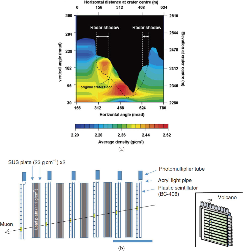
1) In Mt. Asama13),18) and Mt. Shinmoe-dake,22) a change in an internal structure of the top region of the volcano was detected before and after eruption (in 2004 for Mt. Asama and in 2011 for Mt. Shinmoe-dake).
2) In Mt. Satsuma-Iwojima20) dynamics of the lava dome related to magma activity were detected.
3) In Showa-Shinzan lava domes of Mt. Usu,19) the diameter of a magma pathway was measured after the eruption. Similar measurements have been carried out for the Puy de Dome volcano23a) and La Soufriere volcano.23b)
During the course of these developments of volcano research, the following important technical advancements have been made, contributing to the development of the applications of IA CRM radiography to volcanos.
a) Background contribution of decay positron/electron from an in-flight muon is significant so that thick-enough radiation shielding is required as seen in Fig. 8b.21),22)
b) The FWD data requires scattering-in correction of the BWD muons.22)
Further developments are under consideration in the community of volcanic research. In particular, in Japan where the concentration of active volcanos is the highest in the world, approximately 110/378,000 km2, an installation of the muon radiography method of IA type CRM at every active volcano has been suggested.
In order to conduct eruption prediction, in relation to CRM radiography, several other approaches are suggested. The followings are distinguished examples.
1) Volume expansion of volcano which might be related to magma-rise and accumulation on the surface, should precisely be measured by using GPS recorder.
2) Tilt of the slope may be measured to monitor the deformation of a volcano, again related to the magma activity and accumulation on the surfaces.
3) Airborne Synthetic Aperture Rader (SAR),24) which is a high resolution radar attached to an aircraft for interferometric reflection imaging is capable of detecting the summit crater surface structure of an active volcano through eruption cloud.
Obviously, compared to these methods, CRM radiography, although a long-time, like days or months, is required for the data-taking, is able to explore different aspects of the inner-structure of volcano. Combined and complementary use of all of these related methods will contribute to explore phenomena related to eruption prediction, in particular, for the slow process such as a lava-dome formation.
By using IA type CRM transmission radiography, some new directions are proposed for the prediction of the volcano eruption. One example is as follows. Regarding the eruption prediction of presently quiet Mt. Fuji, which is the greatest concern in Japan, a measurement of a possible movement of the ground-water near summit with the IA radiography of the CRM has been proposed in August, 2012 to the Governor of Yamanashi prefecture by the present author with E. Torikai of Yamanashi U. A possible existence of the hydrothermal system just beneath the summit was suggested by the measurements of the maps of electric self-potential and wideband magnetotelluric soundings.25)–27) In the case of La Soufriere of Guadelouse volcano, the density-length mapping of the IA type CRM transmission radiography was found to be correlated with electrical self-potential data and the density mapping by gravity mesurement.23b) Once an existence of hydrothermal system is found beneath the summit of Mt. Fuji, the activity of magma movement might be reflected in the water movement, which could be detected by either IA-CRM radiography or electric self-potential anomaly.
There is another problem for the application of CRM radiography for application to the eruption prediction. The data-taking speed of the IA-CRM which is typically a few days to weeks, is too slow to detect a rapid volcanic process at the top region of the volcano which is the most relevant observables of the CRM radiography. The followings are two possibilities to overcome this difficulty of slow data-taking. 1) Once the object to be examined becomes fixed, e.g. summit region of the specific volcano, by increasing number of counters, data-taking speed will become faster. Presently, most of the CRM Volcano experiments are using a single unit of radiography counter with a limited size of sensitive area like (1 m)2. Increasing the numbers of these counters up to hundreds is not unrealistic at all. 2) As described later, low-energy muon can relatively easily produced by the compact accelerator (CAM). After some future extensive development of accelerator technology, it will become possible to produce GeV muon in a compact and movable way. If this dream becomes realized, a rapid radiography data-taking in a few minutes will become possible.
In the case of the volcano located at a long distance from the CRM radiography detection system, there are some other difficulties such as increase of background events to be removed and the contribution of a loss of the CRM due to the existence of air between the objective volcano and the detectors. The back ground removal possibilities have been discussed in the Shinmoe-dake studies,22) while an air contribution problem for the Mt. Fuji are now under investigation in the Yamanashi U. research group.
3.2. CRM radiography of blast furnaces.
The blast furnaces with typical sizes of 10–20 m diameter for iron burning region surrounded by a carbon brick heat-resist layer of at least 1 m thickness are the relevant objective materials of the IA type CRM transmission radiography. The damage lifetime of carbon brick layer due to the high temperatures of burning iron is an important problem to be monitored. Historically several classical methods had been applied to monitor the thickness change of the carbon brick layer of working blast furnaces. The CRM radiography was applied to this problem in 200528) by using the same set-up of detection system as that used for the volcano studies, namely with two PSDs of (10 cm × 10 cm) resolution in (1 m)2 fiducial area separated by a 1.5 m distance.
The set-up of the experiment, which was conducted at the world’s largest blast furnaces of Dai-ni Kouro at the Oita Factory of the Nippon Steel Corporation during full operation as well as the observed results are shown in Fig. 9a. In 45 days measurement, the thickness of carbon brick layer was determined in a precision of ±5 cm.
Throughout all of these measurements, the following perspective views were obtained.
1) Lifetime of the blast furnaces due to deterioration of carbon brick layers can precisely be determined in the accuracy of ±5 cm out of 1 m total thickness by 45 days of the IA type CRM transmission radiography measurements.
2) The static density of the iron-rich part can be determined to an accuracy of ±0.2 g/cm3 for a volume unit of (0.5 m)3 by 45 days measurements.
3) The time-dependent dynamical behavior of the iron rich part of blast furnaces can be analyzed by a stroboscopic analysis as shown in Fig. 9b, by measuring four cycles of a time dependent change of iron part density, which is triggered by a hot air supply. By terminating hot air supply, the iron region was found to take a different form.
4) More advanced measurement can be done by employing optimized CRM transmission counter, enabling the examination of the following phenomena; burning iron dynamics triggered by external supply of iron fuel, change of furnace operation actions, etc., which will lead to the optimization of operational conditions of blast furnaces.
The next challenging subject is a temperature profile measurement of the iron part in the full operational blast furnaces, which would definitely lead a drastic improvement of operation and control of blast furnaces. Both IA type and SC type transmission radiography methods appear hopeless. One possible method might be, as described later, a reflection radiography measurement of the muon spin rotation of the polarized CRM μ+ in iron, where μ+ spin precession follow temperature-dependent μ+ internal field of ferromagnetic iron. However, in this case, we have to prepare a special instrumentation to measure decay positrons below 50 MeV. Use of either thin (below 20 g/cm2) heat-resistive window or counter enclosure is requested.
3.3. CRM radiography of nuclear reactors.
Intensity attenuation (IA) type CRM radiography has been applied to probe a status of fuel core and pressure vessel of the damaged nuclear reactor. Following initial proposal by the present author to KEK Director General right after the Fukushima Dai-ichi accident happened in March 2011, a simulation calculation has been done in collaboration with K. Ishida of RIKEN, the result of which is shown in Fig. 10a. Then a test experiment has been conducted by the group of KEK and University of Tsukuba to image the present inner-structure of the GM MK-II at the Japan Atomic Power Company,29) which was known to have stopped regular operation and nuclear fuel assembly had been removed.
The detector, consisting of four 1 m × 1 m PSDs made of 1 cm width scintillation fibers. The system was placed at 64 m away from the reactor enter. As seen in Fig. 10b, the empty pressure vessel and movement of the nuclear fuel to the dryer-separator pool were successfully observed. In order to verify this fuel movement, the detector location was changed to nearly opposite position to see clearly the situation of the dryer-separator pool. The measurement was successful. Also the obtained data demonstrated the IA-CRM method is able to detect water-level changes in the reactor vessel and the dryer-separator pool.
Here, let us consider possible application of CMR radiography to probe a real status of the damage for the Fukushima-Daiichi reactors, the largest nuclear reactor accidents in the world. Strong requests exist to explore the status of fuel cores. It should be carried out to investigate the status of damaged nuclear fuel (location and structure) inside pressure vessel or containment vessel. Because of extremely high radiation background, the detector has to be placed outside the reactor building and it has to explore the status of the materials of fuel core, which should be located inside 10-m-thick concrete and 1-m-thick iron enclosures. Before spring 2015, already, two methods have been applied to the Fukushima Daiichi accident; IA type CRM transmission radiography and photography taken by a radioactivity-resident moving robot. The SC type CRM radiography is under preparation. Here, let us compare these approaches.
1) The IA type CRM transmission radiography is the easiest way to detect non-destructively the inner structure from outside by using a single radiography counter, providing an overall inner structure in an allowable measurement time-length. However, the obtained results are distribution of density-length of the materials without element identification; e.g. it is impossible to discriminate a thick Fe from thin U, when each has the same density-length.
2) Visual observation by camera-carrying radiation-resident robot may also able to produce the similar result. Again, it is also difficult for this method to discriminate a thick Fe and thin U.
3) SC type CRM transmission radiography is able to identify the distribution of elements in the inner-part of the damaged reactor. However, it is required to place two radiography detectors at both sides of the damaged reactor. The large detection systems and associated surrounding set-ups have to be prepared. Using the SC type CRM method, by combining with the IA type data, it is possible to do element identification. However, for reliable identification of U wastes against Pb/Fe backgrounds, it is required to obtain a high statistics measurements as described in Section 2.2.2.
4) Recent information for the status of fuel cores inside the damaged Fukushima Daiichi reactors is mostly a molten form during the accident due to reduction of the water level and fuel debris might have relocated to the containment vessel through the pressure vessel. In this situation, muon radiography should need more elaborated improvement. As described later, the use of the most advanced CAM might be the possible solution.
3.4. SC-CRM radiography of cargo containers and other security-related structures.
In order to develop inspection tools for better securing homeland and maritime ports of entry, a method to realize quick (within 20 sec) surveillance and monitoring capability is requested to detect the special nuclear materials hidden in the thick (close to 3 m) heavy enclosures of Fe and/or Pb in large cargo containers, such as oil filled trolleys or ship containers. At the same time, the proposed inspection method should be non-invasive and safely conducted.
Recently, in order to detect the special nuclear materials enclosed inside heavy shields such as a cargo container, in addition to the conventional X-ray radiography, several methods have been proposed and tested; a) fast neutron/gamma-ray radiography (FNGR),30) b) fast neutron resonance radiography (FNRR)31) and c) nuclear resonant fluorescence radiography (NRF).32) In FNGR, simultaneous measurements of intensity attenuation of a fast neutron and gamma-ray will be done to obtain the ratio of these attenuations which is sensitively dependent on the element. In FNRR, fast neutron resonance reactions will be used to make enhanced detection of the light elements. In NRF, by using corresponding high-energy photons produced by a Compton backscattering of intense lasers with high energy electrons, resonant excitation can be expected, causing fluorescence. For generation of 2 MeV photons, use of 800 nm lasers and 300 MeV electrons was suggested.32),33) Unfortunately, all of these methods are unrealistic for use in daily detection of hidden special nuclear materials in heavily shielded cargo-containers; the penetrability of the probing neutrons and photons is too small and detection efficiency is too low.
The SC type CRM transmission radiography may be conducted in a relatively short time (close to 1 min) for the relatively thin (meter scale thickness) specimens because it uses a full intensity of the transmitted CRM as useful data. Therefore this method may be applied to the inspection of the cargo container to detect heavy materials like the special nuclear materials at the import and export places as seen in Fig. 11a.34) In order to identify elements, algorithm for finding of the point of closest approach was considered. However, for more definite element identification, as described earlier, the IA type data is required which takes a longer measurement time.

It has been reported by the LANL group34) that the time required for cargo surveillance is around 1 min, but not less than 20 sec for heavy elements. For an automobile-sized counting station 4 × 4 × 5 m3 six planes of drift tube PSDs were considered for measurement of incoming and outgoing containers. For element identification, such as discriminating between U and Pb, IA data has to be taken simultaneously which may require more than 10 min. Therefore, except some special cases, it is not practical to apply CRM transmission radiography for cargo inspection in general. Alternative method of the CAM method will be described later.
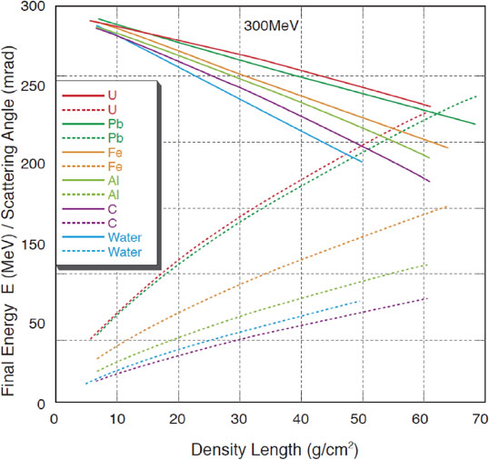
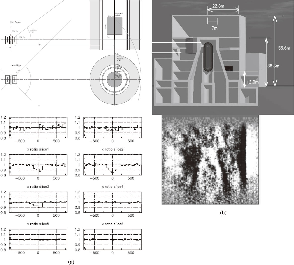
The SC type CRM transmission radiography can be used for other purposes. The specific example is for damaged nuclear reactors, as described earlier. Also, by placing two radiography counters both above (before) and below (after) the specimen to be investigated such as architectural structures, one can detect anomalies in construction status like mechanical destruction of iron rods in reinforced concrete. Examples include bridges and high ways as seen in Fig. 11b.
3.5. Reflection radiography for CRM stopping in the objective materials; X-ray, decay e− and decay e+ μSR.
Before stopping, transmission manner is the same between μ+ and μ−. However, once muons become stopping, each of μ+ and μ− has different characteristics with emission of different reflection signals;1) μ+ takes a stopping location at an interstitial position inside the atomic/molecular crystal and most of the case spin-polarized. In the spin-polarized case, characteristic μSR signals of decay positrons1) are produced as a unique radiography data. On the other hand, μ− forms a small atom around nucleus inside the specimen to be investigated and emits characteristic reflection signals such as the X-ray of muonic atoms and decay electrons with characteristic lifetimes, both of which give useful information regarding the element identification of the stopping material.
There is a weak point in this CRM reflection radiography. There is a limitation on the material thickness due to the range of reflection signals; decay e±, whose energy is below 50 MeV corresponds to the range below 25 g/cm2 and muonic X-ray whose energy is below 10 MeV corresponds to the photon attenuation length below 10 g/cm2.
In general, reflection signal from stopped CRM has the following significant features.
1) Muonic X-ray from the stopped CRM
Precise energy analysis of the muonic X-ray from the CMR stopped in the specimens to be investigated may provide the element composition of the specimens.1)
2) Decay e− from the stopped CRM
Decay life time analysis of the stopping CRM can be used for the element composition analysis of the specimen.1) Some experiments exist for the decay e− measurement as seen in the upper part of Fig. 12.35),36) In addition, there have been some experimental achievements; some for the charge difference measurement of the low-energy CRM and some for the specimen analysis.
3) Decay e+ from the stopped CRM with μ+SR
The CRM has a mixed charge state (μ+ (0.6) and μ− (0.4)) and a partial spin polarization (−0.33 for μ+,3)). Once such a polarized μ+ is stopped in magnetic materials like Fe, observation is expected for a characteristic μ+SR,37) which is a μ+ spin rotation around internal magnetic field at interstitial site.1) Such a measurement was recently done for iron35) as shown in Fig. 12.
Once this method is established, by combining with IA radiography by multiple PSD counters, the signal can be used as a chemical analysis such as a corrosion status of iron rod of the reinforced concrete of aged architectures as seen in Fig. 13. For this purpose a database preparation is required for the μ+SR signal in Fe of various types of reinforced concrete like prestress degree, type of reinforcement, etc. Such database preparation can easily be done by using intense accelerator muons.
There are several subjects to be explored by the μ+SR of stopped CRM. Some examples other than reinforced concrete from the knowledge of the present author are as follows.
1) As mentioned earlier in Section 3.2, temperature profiles of the iron prat of blast furnaces can be measured with detection systems specially designed for decay e+.
2) The CRM is a major component of the environmental radiation. The radiation damage due to CRM has to be investigated closely, which is the subject to be explored under the name of effect of low environmental radiation background. Through detailed studies of the μ+SR of the stopped CRM in biological specimens, this effect can be studied.
4. Perspectives of CAM radiography development in the near future
So far, principles, methods and present status of the transmission radiography of CRM were described for two types of penetration (IA and SC) and one reflection radiography. Here, under the strong expectations of a realization of Compact Accelerator Muon (CAM), we would like to describe a new possible radiography. Roughly speaking, compared to the CRM radiography, because of lower energy of accelerating particles, higher intensity and more advanced beam quality, a delicate control of the beam becomes possible so that the CAM is able to form more relevant basis for the advanced transmission and reflection radiography.
The following scenario can be proposed as a procedure of the present advanced CAM radiography project, which may become the most suitable solution for e.g. a detection of the special nuclear materials (SNM) embedded in the cargo container as mentioned for CRM in Section 3.4.
a) Produce an intense (larger than some 1,000 muons/s) monochromatic (energy width (ΔE/E) better than 1%) and straight (better than 100 mrad) muon beam with the energy penetration capability through the object to be tested.
b) Make a spatial scan of this CAM along the region of the plane of the object to be examined perpendicular to the CAM beam.
c) Collect the data of the transmitted beam energy and the scattering angle of the CAM beam as described later in detail for each scan in a reasonably short time. This will complete element-selective transmission radiography.
4.1. Energy-Loss (EL) and Scattering (SC) measurement in the advanced CAM transmission radiography.
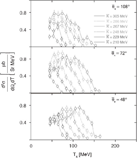
Before going into the details of technical feasibility of CAM, let us consider some general features of the advanced transmission radiography to be realized by the CAM beam. Once intense (at the level of some 103 muons/s), monochromatic (ΔE/E below 1%) and straight (emittance below 100 mrad) CAM beam in a spatial area of (cm)2 becomes available in the energy region of some 100 MeV, the advanced transmission radiography becomes realized as described in the followings.38)
By measuring both energy loss and multiple-scattering angle of the CAM at each point of the specimen to be investigated, one can expect to obtain radiographic data (geometrical integral of density lengths) with element identification as seen in Fig. 14 and Fig. 15. In Fig. 14, energy loss (in terms of final energy from initial accelerated muons of 300 MeV) and scattering angle are presented against density length (thickness) of the specimen through which the 300 MeV muons transmit for various materials. In Fig. 15, for various muon energies, scattering angles are shown against energy loss, where the density length (thickness) is treated as an implicit parameter. These figures are demonstrating a capability of element identification.
For this purpose, the following procedures will be taken.
1) Reasonably monochromatic (better than 1%), convergent (transverse divergent; 100 mrad) and intense (larger than 103/s) beam can be obtained at some 100 MeV energy by re-acceleration of a cooled CAM beam.
2) After transmission through the specimen to be investigated, the energy of the transmitted beam can be obtained by using a calibrated counter with a help of the unique relationship between the energy loss −dE/dX and total energy E. There, the energy loss in the counter appears as the pulse height of the counter-output which can be converted to total energy. Since the initial energy (Eini) is pre-determined at the time of re-acceleration, final total energy of the transmitted muon (Efin) can be converted to energy loss in the objective substance as Eloss = Eini − Efin.
3) Multiple scattering angle of the transmitted CAM can be measured by the multiple PSD as shown in the lower half of Fig. 6 for CRM radiography.
4) By scanning the CAM beam, the inner structure of the specified 100 cm2 region can be explored in 10 sec and 1 cm2 unit area with a statistics of better than 1% in terms of element-selective density length.
4.2. Sources of muons in CAM radiography.
Now let us start to consider suitable accelerator for the CAM, which is compact and possibly movable to the users’ location of radiography measurement; moving the accelerator and radiography measurement system to the place where the measurement is urgently required. Due to recent technological development in both electron and proton accelerators along with the need of compactness for the other application purposes such as medical treatment and industrial application, the realization of such a request becomes not a dream at all. By transporting the entire system to the object to be examined, radiographic imaging data can be obtained in an acceptable measurement time period as described in detail later.
CAM production by using a compact accelerator has been considered in detail.38),39) A possible extension to the cooling and post acceleration for advancement of the process has also been considered,38) as described later.
4.2.1. Sources of CAM by compact electron accelerator.
At present, use of the ∼100 MeV compact electron accelerators is considered to be a standard instrumentation as an injector of the source of the synchrotron radiation, which is the most popular photon sources, being widely used in industrial, medical and materials sciences and industries including national security problems. For example, 300 MeV electron linear accelerator (linac) for synchrotron radiation source is planned to be used as a movable inspection instrumentation device of special architectures such as bridges.
Also, m-scale accelerators have become standard machines for a few 100 MeV electron by using the linac (linear RF accelerator), the FFAG (Frequency Fixed Alternating Gradient Synchrotron) accelerator, the microtron (cyclotron-type accelerator with linear accelerator for accelerating field), etc.
As shown in Fig. 16, the pion production cross section of electron on 12C nuclei is significant at electron energy of 210 to 300 MeV.40) In electron nucleus reactions, muon pair production can occur at high energy like beyond GeV. By some 100 MeV energy electrons, pions are mainly produced in photoelectric effect followed by muon production by pion decay. The photoelectric effect can be written as e− + Z1 → γ + π± + Z2. In this case, threshold energy is close to the pion mass (140 MeV) for both π+ and π−, which is a good feature for a realization of the CAM with electron accelerator.
Following pion photo-production, capturing of pions and pion-to-muon decay section has to be prepared to produce a useful muon beam for radiography. An example of a realistic form of a (non-advanced) CAM radiography system by using a 300 MeV microtron39) is shown in Fig. 17.
4.2.2. Sources of CAM by compact proton accelerator.
Accelerated protons are able to produce pions more efficiently than electrons. At the same time, proton radiation therapy recently becomes very popular for several reasons. The 250 MeV or lower energy protons are stopped inside the human body, where the proton stopping position can be controlled in order to set the position of the proton Bragg peak to be matching to the cancer tissue to be treated. There, for cost reduction and simplification of operational conditions of hospital personnel, it is requested to accommodate proton accelerator inside a single room of treatment in a medical hospital, within a size of 10 m × 10 m × 10 m. For this purpose, a small and compact 250 MeV proton synchrotron becomes commercially available by using a strong superconducting magnetic field and by making an accelerator as a part of the gantry, which is a beam delivery and control device. An example is presented in Fig. 18.41) In order to realize such a compact proton accelerator, there is a possibility to use synchro-cyclotron with high field (more than 5 T) superconducting coils. Recently, a private company has built such a single room unit for proton therapy, where a compact 9 T superconducting synchro-cyclotron (SC-SC) is located near the patient. Some known parameters of these commercial SC-SC are summarized in Table 2.

Table 2. Parameters of SC-SC for proton therapy
| |
SC-SC NSCL MSU41) |
MEVION-S25041) |
| Energy (MeV) |
250 |
250 |
| Beam Current (nA) |
200–400 |
50 |
| Repetition (kHz) |
1 |
0.5 |
| Field (T) |
5.5–4.9 |
9 |
| Magnet size, cm |
264 × 173 |
|
| Diameter, cm |
|
91 |
| Magnet weight, tons |
65 |
<20 |
There are several important features of proton-CAM compared to electron-CAM, as summarized in the followings.
1) Produced muon intensity normalized to input accelerator power is lager.
2) Although most of the transmission radiography methods do not depend on the charge of the CAM, positive muons are more abundantly produced.
3) Spin polarization is easily obtained so that reflection radiography of the μ+ spin rotation/relaxation signal is always applicable for the proton-CAM, as some examples will be mentioned later.
The energy of 250 MeV is close to the pion production threshold in free nucleon-nucleon reaction such as p + p → p + n + π+ (2 times pion mass ≈ 280 MeV). As shown in Fig. 19a for the case of proton-14N reaction,42) like other proton-nucleus reactions, reasonably intense pions can be produced with the help of nucleon Fermi energy inside the target nucleus. Here, both pion-energy-integrated pion-angle dependence42) in Fig. 19a and emission-angle-integrated pion-energy dependence43) are shown in Fig. 19b. Following these data, the pion production at 250 MeV proton seems to be close to isotropic and energy independent up to 100 MeV pion energy.

As in the case of the electron accelerator, produced pions have broad energy spectrum and wide angular distribution. Also, muons are produced from the decay of pions which are either in flight or stopped for the case of π+. Thus, produced muons of the CAM have a large spread in both energy and spatial direction. On the contrary, for advanced transmission radiography, as described earlier, monochromatic and straight muon beam is necessary. Thus, there seems to be a problem in direct application of CAM to advanced radiography.
As described later, there is a solution. One intermediate solution is the use of a large acceptance pion/muon capture and confinement beam optics for the pion to muon decay in-flight inside the superconducting solenoidal field. One example is presented in Fig. 20a, which is called Large-Omega (LΩ), and is an extension version of the Dai-Omega developed at KEK.44) The other one is presented in Fig. 20b, which is called Ultra-high Intensity Muon Production by long Superconducting Solenoid (UIMPS), is an extreme limit of the confinement optics.
4.3 Feasibility of CAM source for Radiography.
It is important to understand how the CAM is a feasible concept for radiography application. The problem is related not only to muon intensity (yield) but also to beam quality (mono-chromaticity and straightness) which should be good enough for the purpose of advanced radiography. Here for the cases of both electron and proton accelerators, some critical examinations are made based upon experimental data.
4.3.1 Pion/Muon yields of CAM.
By using experimental data of the double differential cross section d2σ(Eπ, θπ, Eb)/dEπdθπ, the pion yield can be written as follows,
| \begin{align}
Y_{\pi} &= I_{b}\times \iint(d^{2}\sigma(E_{\pi},\theta_{\pi},E_{b})/dE_{\pi}d\theta_{\pi})\delta E_{\pi}\delta\varOmega_{\pi}\\
&\quad\times (nt)
\end{align}
| [5] |
where
Eb and
Ib are the energy and the current of the accelerator of electron or proton, respectively. There,
Eπ and θ
π are energy and emission angle of the produced pions, respectively. In order to simplify the argument, let us consider for the double differential cross section,
d2σ(
Eπ, θ
π,
Eb)/
dEπdθ
π to take constant values (
Eπ and θ
π independent) for the selected
Eb and
Eπ as seen in
Fig. 16 and 19a/19b from the data of references.
39),42),43) Then, pion yields are estimated as listed in
Table 3. For δ
Eπ and δ
Ωπ, we assumed the use of LΩ type optics described later. The size of the pion source is within an area of proton beam size times target thickness.
Table 3. Pion yields of the CAM candidate accelerators with LΩ pion capture beam optics
| |
Electron
Accelerator |
Proton
Accelerator |
| Ebeam |
300 MeV |
250 MeV |
| Ibeam |
1 µA
(0.63 × 10¹³/s) |
50 nA
(3.2 × 10¹¹/s) |
| dσ(Eπ, θπ)/dEπdθπ |
0.4 × 10⁻³⁰ for μ+,−
(cm2/MeV/sr) |
2.0 × 10⁻³⁰ for μ+
(cm2/MeV/sr) |
| δEπ (LΩ optics) |
10 MeV |
10 MeV |
| δθπ (LΩ optics) |
1 sr |
1 sr |
| Nt (1 cm C) |
1.1 × 10²³
(/cm3) |
1.1 × 10²³
(/cm3) |
| Yπ |
0.3 × 10⁷/s |
0.7 × 10⁶/s |
Let us consider the three beam optics for pion to muon conversion
1) Large Omega (LΩ) type. As seen in Fig. 20a and Table 3, the pions from the electron/proton targets are collected in a geometrical acceptance of 1 sr and energy acceptance of 10%; e.g. from 65 MeV (150 MeV/c) to 75 MeV (163 MeV/c). As shown in Fig. 20a, a 6 m long confined decay section is prepared for muon production.
2) UIMPS type. Contrary to the LΩ case, in order to make a full capture and a full conversion of the produced pions, both the pion production target and the target of muon irradiation are placed inside the 10 T, 15 cm aperture and 10 m long superconducting solenoid as seen in Fig. 20b. The pions are captured in 2π sr and 0 to 200 MeV/c (104 MeV). The solenoid is almost long enough of the required decay length for 200 MeV/c (11.2 m) and wide enough to accommodate the maximum momentum of forward decay muons (orbit diameter of 7.0 cm for 209 MeV/c).
3) Surface μ+ type. By giving up μ− use for the radiography purposes, we can use 4 MeV surface μ+, which is generated by π+ (stopped) → μ+(4 MeV, 30 MeV/c) + νμ at the surface of the production target.1) Since the μ+ is generated at the pion production target as a secondary beam, a high acceptance capture of surface μ+, some monochromaticity and some straightness can be obtained. According to our preliminary estimation for 250 MeV and 50 nA proton, as shown in Table 4, expected surface μ+ intensity (6 × 10⁴/s) was obtained, which is encouraging for further application to the advanced CAM radiography.
Table 4. Muon Yields for the CAM candidate accelerators with LΩ muon optics
| |
Electron
Accelerator
(300 MeV, 1 µA) |
Proton
Accelerator
(250 MeV, 50 nA) |
| Yπ |
0.3 × 10⁷/s |
0.7 × 10⁶/s |
| LΩ optics (65–75 MeV pion) |
| Energy Width |
10 MeV |
| Straightness |
370 mrad |
| Conv. Rate |
0.49 × 0.89 |
| Intensity Yμ |
0.13 × 10⁷/s |
0.3 × 10⁶/s |
| Surface μ+ Optics (4 MeV muon) |
| Energy Width |
1.0 MeV |
| Straightness |
260 mrad |
| Conv. Rate |
1.0 |
| Intensity Yμ |
0.63 × 10⁵/s |
Other than surface μ+, the intensity of the muons which are produced by the in-flight decay of pions during the passage under confinement solenoidal field can be estimated as follows;
| \begin{equation}
{Y_{\mu}= \iiiint Y_{\pi} (E_{\pi}, \theta_{\pi})\varepsilon_{\pi\mu}(E_{\pi},\theta_{\pi},E_{\mu},\theta_{\mu})\delta E_{\pi}\delta\varOmega_{\pi}\delta E_{\mu}\delta\varOmega_{\mu}}
\end{equation}
| [6] |
where ε
πμ(
Eπ, θ
π,
Eμ, θ
μ) is the conversion efficiency of pion decay kinematics during a flight of the pions under a long confinement field and the collection efficiency of the produced muons by energy and solid-angle acceptance of the ending part of the muon channel, δ
Eμ and δ
Ωμ, respectively. In the confinement field and for the average single value of
Yπ, it is approximated to,
| \begin{equation}
Y_{\mu} = Y_{\pi}\varepsilon_{\pi{\text{⇢}\mu}}.
\end{equation}
| [7] |
| \begin{equation*}
\varepsilon_{\pi{\text{⇢}\mu}} = Y_{\pi}[1- \exp(-L/L_{d})]\times\delta\varOmega_{\textit{corr}}.
\end{equation*}
|
where
Ld is the in–flight decay length of pion with momentum
pπ;
Ld (cm) = 5.593
pπ (MeV/c). There, δ
Ωcorr is the fraction of muons which come from the decay of in-flight pions and are collected by the optics efficiency with a correction due to π–μ decay-kinematics.
4.3.2. Muon beam characteristics at the exit of confined pion decay section in CAM.
As already mentioned at the beginning of this Chapter (Section 4.1), the final goal of the CAM advanced transmission radiography is the measurement of energy loss and scattering of a monochromatic and straight CAM beam. Also, as presented there, considering the results of simulation calculation shown in Figs. 14 and 15, the requirements for CAM at some 100 MeV to be used for advanced element-selective radiography are monochromatic (better than 1%), convergent (smaller than 100 mrad) and intense (103/s) muon beam.
Now, concerning the proposed CAM beam as described so far, let us summarize what kind of muon beam can be expected at the exit of the large acceptance pion capture and the pion-to-muon decay section of the LΩ and 4 MeV surface μ+.
For CAM from a 250 MeV proton accelerator, the muon yield, energy width and the straightness which is the maximum beam gradient at the focus including effect of pion-decay kinematics are shown in Table 4 for decay-in-flight μ+ from 65–75 MeV pion capture by LΩ (for the surface μ+ with LΩ capture and transport). The Yield of μ+ is 0.7 × 10⁶/s (0.6 × 10⁵/s), where the μ+ beam has a beam spot of within cm-diameter with 10 MeV (1 MeV) energy spread and 370 mrad (260 mrad) straightness.
Thus, by a direct use of the CAM beam from the LΩ optics, it is difficult to satisfy the requirements for the advanced radiography. As a relevant alternative new idea, the following scheme has been proposed.39)
4.4. Advanced transmission radiography with CAM.
By using compact electron or proton accelerator and by employing the succeeding cooling and post acceleration of the muon beam as seen in Fig. 21, one can generate the μ+ beam with high energy (up to some 100 MeV), high energy resolution (below a few keV) and high straightness (below 10 mrad), which can powerfully be used for element-selective transmission radiography.39)
Here we consider the use of 250 MeV 50 nA proton accelerator coupled with the LΩ optics.
a) Production and capture of intense MeV to 100 MeV π+ beam or 4 MeV surface μ+ beam from a solid production target.
b) A confinement transport of MeV to 100 MeV π+ and the production of μ+ by the pion decay in-flight under 10 (5) T, 10 (20) cm aperture and 6 m long superconducting solenoid of LΩ, which provides intense MeV to some 10 MeV μ+ beam as seen in Table 4 onto hot W target. Alternatively, 4 MeV surface μ+ can be transported without significant loss to the exit of the LΩ and to hot W target.
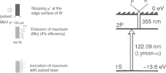
c) After stopping these decay μ+ or surface μ+ in 50 µm thick hot (2000 K) W, thermal muonium is produced from the surface of hot W.45) The produced thermal muonium can be ionized by the laser resonant ionization46) (muonium 1s-2p resonant excitation by using 122 nm laser obtained by the 4-wave mixing method and muonium 2p ionization by 355 nm laser as shown in Fig. 22), providing an intense low energy (below keV) μ+ source47) for post acceleration as seen in Fig. 22. This method is now considered to be the preferred method to produce intense slow μ+ beam.48) Recently some development has been made for the required intense pulsed lasers.49)
d) Post acceleration from sub-keV up to desirable energies such as 100 MeV for transmission radiography of the specimen to be investigated by high repetition and high acceleration gradient linac. Because of the normalized emittance conservation law, βγεlab is conserved, where εlab is laboratory emittance. Thus, by accelerating UCM, narrow beam of smaller (x, y) size is obtained in free space.48)
All of these schemes and the proposed element-selective radiography system are schematically shown in Fig. 21. There, the transmission radiography of the advanced CAM can be seen in the right-end part of the figure, where both a single multiple scattering counter for the transmitted beam of the in-coming straight muon beam and a single energy counter for the emitting muon beam are prepared. Here, obviously a range of the initial energy of the advanced CAM should be larger than the range thickness of the specimen to be investigated. One example is 300 MeV CAM beam which can penetrate thick container with 50 g/cm2 U enclosed by 50 g/cm2 Fe.
Let us argue quantitatively regarding the feasibility of advanced CAM radiography in terms of intensity and beam quality. Here we consider to use 250 MeV 50 nA proton accelerator coupled with the LΩ pion/muon optics.
a) As summarized in Table 3, μ+ Yield of decay-in-flight μ+ (surface μ+) by using proton CAM, is 0.7 × 10⁶/s (0.6 × 10⁵/s) in a beam spot of within cm diameter with 10 MeV (1 MeV) energy spread and 370 mrad (260 mrad) straightness.
b) Stopping this μ+ in 50 µm hot W with an intensity of 5 × 10⁴/s (6 × 10⁴/s) corresponding to a fraction of range difference of 0.075 (1).
c) From this stopped μ+, USM of laser ionization of thermal muonium can be produced in an intensity of 2.5 × 10²/s (3 × 10²/s) with an efficiency of 0.5%. The energy of ionized μ+ is below 100 eV.
d) This intensity of 2.5 × 10²/s (3 × 10²/s) will be maintained by RFQ capture/acceleration and Linac of post accelerator from MeV to some 100 MeV. Because of normalized emittance conservation, straightness becomes smaller than 10 mrad.
Using the result of these considerations, the transmitted CAM at some specified region of the specimen to be investigated can be used to measure the relation of the energy loss and the multiple scattering angle at each crossing point of the beam in the specimen to be investigated. As seen in Figs. 14 and 15, element identification can be achieved. By collecting all the events from various spatial regions, element-selective radiography can be carried out in a short time such as below 20 s. The above-mentioned homeland security problem will be solved.
4.5 Some significant possible applications of the advanced CAM radiography.
By using the advanced CAM with relevant detection systems of IA and SC transmission radiography and μ+SR reflection radiography, one can explore the following new aspects of inner-structure of thick materials in a sub-mm spatial resolution; density distribution, element distribution, chemical status, etc. Thus, the following applications will become possible for the first time.
-
a)
Detection of special nuclear materials hidden in cargo containers in a relatively short time like within 20 s. When they are enclosed in iron or lead sheets with the thickness more than 5 cm, no other penetrating radiations can be used.
-
b)
Inspection of radioactive materials from outside. Even enclosed within lead shielding, one can identify inside materials. By a special arrangement of the CAM beam optics, inner-structure of the materials located above the beam line can be probed. Some good detection conditions can be considered to examine status of the fuel debris of the damaged nuclear reactors.
-
c)
Point-to-point spatial μSR analysis of a relatively thick (human body scale) specimen will have various applications in life and medical science. Representative examples are as follows: 1) Detection of deficient part of oxygen molecule in specific organ in human body which is related to the growth of the cancer tissue called as Hypoxia (low oxygenation). Recently it was found that muonium relaxation can be applied to this problem;50) 2) By μ+SR reflection radiography, after stopping in a specific part of the human brain, via the change of the μ+SR pattern, one can easily identify oxy/deoxy state of the hemoglobin in blood of human brain.51) A key and new information of the brain function can be studied; 3) Probing radiation effects induced by the muon irradiation itself through a change of the electron transfer phenomena by the labelled electron method.52)
-
d)
Examination of physical and chemical status of iron rods in reinforced concretes of aged architectures. Within a short time below 1 min, chemical status will be known through a change of μ+SR pattern (precession frequency, relaxation rate, etc.), as demonstrated for CRM case in Section 3.5.
5. Conclusion
Muons obtained as cosmic-ray on the surface of the earth (CRM) and as compact-accelerator produced beam (CAM) can be used to explore the details of the inner structure of large-scale objects with thickness in the nm to km range; nm to m for CAM and m to km for CRM.
The use of non-destructive CRM radiography for industrial and homeland-security purposes should be encouraged. The most urgent application is the exploration of the detailed inner-structure of the damaged nuclear reactors, in particular, of Fukushima-Daiichi which had been damaged by the Tohoku earthquake and tsunami in March 2011. Both IA and SC types of transmission radiography should extensively and systematically be applied. The final goal of Fukushima-Daiichi reactor problem is to identify the status of fuel debris of Uranium core rod after the accident by removing background signals of other materials such as Fe and Pb via combined measurements of IA and SC transmission radiography.
Although there have not been any actual realizations so far, it is highly recommended to realize the CAM by using either proton accelerators or electron accelerators. By cooling and re-acceleration, the CAM radiography will have an advantage property of element selectivity.
Finally, let us mention rough estimates of required costs of the above mentioned instrumentations of muon radiography methods. As for CRM, the IA transmission in the size of 1 m × 1 m two plastic scintillator PSDs planes need a few 0.1 M$, while the SC transmission in the size of the 4 m × 4 m six drift tubes PSDs planes need a few M$.25) As for the CAM, all the system shown in Fig. 20 needs close to 10 M$ with the following components; 250 MeV proton accelerator (5 M$), muon collection and cooling (1.5 M$), muon re-acceleration (3 M$) and radiography detector (0.5 M$).
Profile

Kanetada Nagamine was born in 1941 in Hayama, Kanagawa. He graduated from the University of Tokyo and became Associate Professor in 1978 and Professor in 1989 of Meson Science Laboratory of the University of Tokyo until 2002, while jointly served Professor of High Energy Accelerator Research Organization (KEK) during 1997–2004, Laboratory Head of RIKEN Muon Science Laboratory during 1984–2001 and Research Physicist of University of California, Riverside (UCR) since 2003. Currently, he is emeritus status of UT, KEK and RIKEN. Also he is at the same position of UCR and Visiting Professor of University of Yamanashi. He is the world-leader of muon science research and has successfully initiated and developed many projects on muon science and associated facility constructions. Examples are 1) the initiation and development of scientific research utilizing pulsed muons provided by a proton synchrotron and the construction of related experimental facilities of both KEK Meson Science Laboratory (extended to J-PARC MUSE) in Japan and RIKEN-RAL (Rutherford Appleton Lab.) Muon Facility in UK, 2) condensed matter research with long-time-range muon spin relaxation measurements and pulsed-rf muon spin resonance using pulsed muons, 3) thermal muonium production in vacuum and its ionization by lasers to produce ultra-slow μ+ for surface science research and fundamental physics research, 4) a new experimental method for muon catalyzed fusion by pulsed muons, 5) the labeled electrons with positive muons for electron transport measurements in conducting polymers and biological macro-molecules, 6) geophysical studies like viewing inner-structure of volcanoes with cosmic-ray muons and inspection of a large-scale industrial machinery like blast-furnaces and nuclear reactors. He received Inoue Science Award in 1990 and Toray Science and Technology Prize in 2003.
Acknowledgements
For CRM radiography measurements, strong supports and helps of Drs. H.M.K. Tanaka, K. Ishida, S.N. Nakamura, M. Iwasaki, K. Shimomura in the early stage of collaboration and those of Drs. M. Hashimoto, A. Shinotake and A. Hatanaka in the project on blast furnace and those of Drs. H. Fujii, K. Hara, F. Takasaki, C.L. Morris, E. Milner, H. Miyadera in the later projects on damaged nuclear reactor and those by Drs. E. Torikai, A.D. Pant and Mr. T. Fujimaki for CRM μSR radiography are greatly acknowledged. For CAM radiography, various design works and discussions with Drs. H. Miyadera, A.D. Jason, Y. Mori, Y. Miyake, A.P. Mills Jr., S. Chu and J. Marangos are greatly appreciated. Further, Professors J.S. Schultz, T.P. Das, Y. Sugawara for various aspects of bio-medical applications. Special thanks to Ms. N. Ichimura for preparation of drawings. The author is grateful for encouragements by Professors T. Yamazaki, the late M. Oda and the late Y. Totsuka. The present writing work is partly supported by “Ultra-Slow Muon Microscope” (No. 23108003) Grant-in Aid for Scientific Research on Innovative Areas from the Ministry of Education, Culture, Sports, Science and Technology (MEXT) of Japan.
References
- 1) Nagamine, K. (2003) Introductory Muon Science. Cambridge University Press, Cambridge, 1–208.
- 2) Adair, R.K. and Kasha, H. (1976) Cosmic-ray muons. In Muon Physics (eds. Hughes, V.W. and Wu, C.S.). Vol. 1, Academic Press, New York, pp. 323–385.
- 3) Turner, R. (1971) Polarization of cosmic-ray muons. Phys. Rev. D 4, 17–23.
- 4) Nandi, B.C. and Sinha, M.S. (1972) The momentum spectrum of muons at sea level in the range 5–1200 GeV/c. J. Phys. A: Gen. Phys. 5, 1384–1394.
- 5) Ayre, C.A. (1975) Precise measurement of the vertical muon spectrum in the range of 20–500 GeV/c. J. Phys. G: Nucl. Phys. 1, 584–600.
- 6) Kelogg, R.G. (1978) Momentum spectra, charge ratio, and zenith-angle dependence of the cosmic-ray muons. Phys. Rev. D 17, 98–113.
- 7) Tsuji, S. (1998) Measurements of muons at sea level. J. Phys. G: Nucl. Part. Phys. 24, 1805–1822.
- 8) Jokisch, H. (1979) Cosmic-ray muon spectrum up to 1 TeV at 75° zenith angle. Phys. Rev. D 19, 1368–1372.
- 9) Matsuno, S. (1984) Cosmic-ray muon spectrum up to 20 TeV at 89° zenith angle. Phys. Rev. D 29, 1–23.
- 10) Reyna, D. (2008) A simple parameterization of the cosmic-ray muon momentum spectrum at the surface as a function of zenith angle. In hep-ph/0604145v2; , Bugaev, E.V. (1998) Atmospheric muon flux at sea level, underground and underwater. Phys. Rev. D 58, 054001-1-7.
- 11) Alvarez, L.W. (1970) Search for hidden chambers in the pyramids. Science 167, 832–839.
- 12) Nagamine, K. (1995) Method of probing inner-structure of geophysical substance with the horizontal cosmic-ray muons and possible application to volcanic eruption prediction. Nucl. Instrum. Methods Phys. Res. A 356, 585–595.
- 13) Tanaka, H.K.M. (2003) Development of a two-fold segmented detection system for near horizontally cosmic-ray muons to probe the internal structure of a volcano. Nucl. Instrum. Methods Phys. Res. A 507, 657–669.
- 14) Tanaka, H.K.M. and Nagamine, K. (2003) Probing inner-structure of volcano with cosmic-ray muons. Kazan 48, 345–366 (in Japanese).
- 15) Uchida, T. (2009) Space saving power efficient readout system for cosmic-ray muon radiography. IEEE Trans. Nucl. Sci. 56, 448–452.
- 16) Borozdin, K.N. (2003) Radiographic imaging with cosmic-ray muons. Nature 422, 277.
- 17) Morris, C.L. (2012) Obtaining material identification with cosmic ray radiography. AIP Adv. 2, 042128.
- 18) Tanaka, H.K.M. (2007) Development of an emulsion imaging system for cosmic-ray muon radiography to explore the internal structure of a volcano, Mt. Asama. Nucl. Instrum. Methods Phys. Res. A 575, 489–497; , Tanaka, H.K.M. (2007) High resolution imaging in the inhomogeneous crust with cosmic-ray muon radiography: the density structure below the volcanic crater floor of Mt. Asama, Japan. Earth Planet. Sci. Lett. 263, 104–113.
- 19) Tanaka, H.K.M. (2008) Muon radiography and deformation analysis of the lava dome formed by the 1944 eruption of Usu, Hokkaido. Proc. Jpn. Acad., Ser. B 84, 107–114.
- 20) Tanaka, H.K.M. (2009) Cosmic-ray muon imaging of magma in a conduit: depassing process of Satsuma-Iwojima volcano, Japan. Geophys. Res. Lett. 36, L013041-5.
- 21) Tanaka, H.K.M. (2014) Radiographic visualization of magma dynamics in an erupting volcano. Nat. Commun. 5, 3381–3390.
- 22) Kusagaya, T. and Tanaka, H.K.M. (2015) Development of the very long range muographic imaging technique to explore the internal structure of an erupting volcano, Shinmoe-dake, Japan. Geosci. Instrum. Method. Data Syst. 4, 215–226.
- 23) (a) Saracino, G. (2012) Looking at volcanoes with cosmic-ray muons. Phys. Today 65, 60–61. , (b) Lesparre, N. (2012) Density muon radiography of La Soufriere of Guadeloupe volcano: comparison with geological, electrical resistivity and gravity data. Geophys. J. Int. 190, 1008–1019.
- 24) Urabe, B. (2006) Topographic change of the summit crater of Asama Volcano during the 2004 eruption derived from Airborne Synthetic Aperture Radar (SAR) measurements. Bull. Geographical Survey Inst. 53, 1–6.
- 25) Aizawa, K. (2004) A large self-potential anomaly and its changes on the quiet Mt. Fuji, Japan. Geophys. Res. Lett. 31, L05612.
- 26) Aizawa, K. (2005) Hydrothermal system beneath Mt. Fuji volcano inferred from magnetotellurics and electric self-potential. Earth Planet. Sci. Lett. 235, 343–355.
- 27) Kagimoto, T. (2007) Structure of Fuji volcano. In Fuji Volcano (eds. Aramaki, S., Fujii, T., Nakata, S. and Miyaji, N.). Yamanashi Institute of Environmental Sciences, pp. 137–150 (in Japanese).
- 28) Nagamine, K. (2005) Probing the inner-structure of Blast furnaces by cosmic-ray radiography. Proc. Jpn. Acad., Sci. B 81, 257–260.
- 29) Fujii, H. (2013) Performance of a remotely located muon radiography system to identify the inner structure of a nuclear plant. Prog. Theor. Exp. Phys. 073C01 (20 pages).
- 30) Liu, Y. (2008) Comparison of neutron and high-energy X-ray dual-beam radiography for air cargo inspection. Appl. Radiat. Isot. 66, 463–473.
- 31) Sowerby, B.D. (2007) Recent advances in fast neutron radiography for cargo inspection. Nucl. Instrum. Methods Phys. Res. A 580, 799–802.
- 32) Bertozzi, W. (2005) Nuclear resonance fluorescence imaging in non-intrusive cargo inspection. Nucl. Instrum. Methods Phys. Res. B 241, 820–825.
- 33) Pruet, J. (2006) Detecting clandestine material with nuclear resonance fluorescence. J. Appl. Phys. 99, 123102.
- 34) Morris, C.L. (2008) Tomographic imaging with cosmic-ray muons. Sci. Global Security 16, 37–53; , Schultz, L.J. (2004) Image reconstruction and material Z discrimination via cosmic ray muon radiography. Nucl. Instrum. Methods Phys. Res. A 519, 687–694.
- 35) Nagamine, K. (2014) Cosmic-ray muon spin rotation in Fe and industrial application. J. Phys.: Conf. Ser. 551, 012064 1–4.
- 36) Fujimaki, T. (2015) Materials science observation of large-scale architectures by cosmic-ray muon. Contribution to 2015 9th Joint Research Meeting of MEXT National Projects on Condensed-Matter Science (November, the University of Tokyo).
- 37) Nishida, N. (1977) Hyperfine field and diffusion of μ+ in Fe single crystals. Solid State Commun. 22, 235–239.
- 38) Nagamine, K. (2004) Advanced muon radiography with compact accelerator. Proc. Jpn. Acad., Ser. B 80, 179–182.
- 39) Nagamine, K. (2008) Compact muon source with electron accelerator for a mobile μSR facility. Physica B 404, 1020–1023.
- 40) Arends, J. (1982) Inclusive charged pion photoproduction on 12C using tagged photons in the energy range (200–390) MeV. Z. Phys. A, At. Nucl. 305, 205–212.
- 41) Papash, A.I. (2010) Compact superconducting synchrocyclotrons at magnetic field level of up to 10 T for proton and carbon therapy. Proc. RuPAC-2010 THPSC037, 393–395; , MEVION medical systems. (2015) MEVION S250th. Private communication (April).
- 42) Martensson, J. (2000) Pion production excitation functions in proton-nucleus collisions from the absolute threshold to 500 MeV. Phys. Rev. C 62, 014610 1–11.
- 43) DiGiacomo, N.J. (1985) Inclusive pion production in 330, 400, 500 MeV proton-nucleus collisions. Phys. Rev. C 31, 292–294.
- 44) Miyadera, H. (2006) Design, construction and performance of Dai Omega, a large solid-angle axial-focusing superconducting surface-muon channel. Nucl. Instrum. Methods Phys. Res. A 569, 713–726.
- 45) Mills, A.P. Jr. (1986) Generation of thermal muonium in vacuum. Phys. Rev. Lett. 56, 1463–1466.
- 46) Chu, S. (1988) Laser-excitation of the 1s–2s transition in muonium. Phys. Rev. Lett. 60, 101–104.
- 47) Nagamine, K. (1995) Ultraslow positive-muon generation by laser ionization of thermal muonium from hot tungsten at primary proton beam. Phys. Rev. Lett. 74, 4811–4814.
- 48) Nagamine, K. (2014) Past, present and future of ultra-slow muons. JPS Conf. Proc. 2, 010001 (8 pages).
- 49) Saito, N. (2012) Development of Short-Wavelength Radiations and Their Applications. The 427th Topical Meeting of the Laser Society of Japan RTM-12-15, 49–54.
- 50) Pant, A.D. (2014) Muonium response to oxygen content in biological aqueous solutions for cancer research. J. Phys.: Conf. Ser. 551, 012043 1–5.
- 51) Nagamie, K. (2007) Hemoglobin magnetism in aqueous solution probed by muon spin relaxation and future applications to brain research. Proc. Jpn. Acad., Ser. B 83, 120–126.
- 52) Nagamine, K. and Torikai, E. (2004) Electron transfer in protein and DNA probed by muon spin relaxation. J. Phys. Condens. Matter 16, S4797–S4806.