Abstract
The interconversion between spin, charge, and heat currents is being actively studied from the viewpoints of both fundamental physics and thermoelectric applications in the field of spin caloritronics. This field is a branch of spintronics, which has developed rapidly since the discovery of the thermo-spin conversion phenomenon called the spin Seebeck effect. In spin caloritronics, various thermo-spin conversion phenomena and principles have subsequently been discovered and magneto-thermoelectric effects, thermoelectric effects unique to magnetic materials, have received renewed attention with the advances in physical understanding and thermal/thermoelectric measurement techniques. However, the existence of various thermo-spin and magneto-thermoelectric conversion phenomena with similar names may confuse non-specialists. Thus, in this Review, the basic behaviors, spin-charge-heat current conversion symmetries, and functionalities of spin-caloritronic phenomena are summarized, which will help new entrants to learn fundamental physics, materials science, and application studies in spin caloritronics.
1. Introduction
Thermoelectric effects enable direct interconversion between heat and electricity.1) One of the representative thermoelectric effects is the Seebeck effect, discovered by T. J. Seebeck in 1821. This effect converts a heat current into a charge current in metals and semiconductors. Its performance is described by the Seebeck coefficient, which is defined as the ratio of the generated electric field to the applied temperature gradient. The Onsager reciprocal of the Seebeck effect is called the Peltier effect, discovered by J. C. A. Peltier in 1834. Since the discovery of these fundamental effects, physics, materials science, and application-oriented studies on thermoelectric effects have mainly focused on thermoelectric power generation based on the Seebeck effect and electronic cooling based on the Peltier effect.
In addition to the Seebeck and Peltier effects, various thermoelectric transport phenomena appear in a conductor in the presence of a magnetic field H or in a magnetic material with spontaneous magnetization M.2) Such phenomena include the magneto-Seebeck/Peltier effect, in which the Seebeck/Peltier coefficient depends on the magnitude and direction of H or M, and the Nernst (Ettingshausen) effect, in which a heat (charge) current induces a transverse charge (heat) current perpendicular to H or M (Fig. 1). In magnetic conductors, the magneto-thermoelectric effects appear even in the absence of an external magnetic field owing to the action of the spin-orbit interaction on spin-polarized conduction electrons. Although these magneto-thermoelectric effects have been known for a long time, some of these phenomena have not been investigated in detail. The magneto-thermoelectric effects are fascinating research subjects that remain to be studied from fundamental and applied points of view.
In the past few decades, extensive research on spintronics, in which electron spins are actively exploited as new information and energy carriers in addition to electron charge, has been carried out all over the world.3) The field of spintronics has seen both important scientific discoveries and industrial applications, such as hard disk drive read heads, magnetoresistive sensors, and magnetic random access memories.4),5) A key concept in spintronics is the spin current, which is a pure flow of spin angular momentum without an accompanying charge current. The spin current is used for information writing and reading in spintronic devices. The concept of the spin current has also triggered the discovery of various spin-dependent and spin-driven transport phenomena; principles and techniques for generating, detecting, and controlling spin currents have developed rapidly since the beginning of the 21st century.
In this stream, the interplay between spin, charge, and heat currents has been extensively investigated. The research field based on the combination of thermoelectrics and spintronics is called spin caloritronics.2),6) This field originated from the theoretical study by Johnson and Silsbee in 1987, which established the nonequilibrium thermodynamics of the spin-charge-heat interaction in metal-based magnetic heterostructures.7) Several decades later, Hatami et al. theoretically predicted that the M direction of a ferromagnet can be reversed by a spin-polarized heat current and introduced the term “spin caloritronics”.8) One of the triggers for the rapid development of spin caloritronics is the discovery of the spin Seebeck effect (SSE), which refers to the generation of a spin current as a result of a heat current in magnetic materials.9)–12) To clarify the mechanism of the SSE, many condensed matter physicists began research on spin caloritronics. Today, spin caloritronics has grown into an interdisciplinary field which is studied worldwide. Since the discovery of the SSE, novel thermo-spin conversion principles have been discovered one after another, and unconventional thermoelectric functionalities based on spin caloritronics have been demonstrated.
The aim of this Review is to summarize the basic behaviors, spin-charge-heat current conversion symmetries, and functionalities of various spin-caloritronic phenomena. This Review is organized as follows. In Sec. 2, we focus on the conversion between charge and heat currents in magnetic materials, that is, the magneto-thermoelectric effects that depend on the M direction (Fig. 1). Although detailed explanations of magnetic-field-dependent magneto-thermoelectric effects which appear even in nonmagnetic materials are omitted, the symmetries of these effects are the same as those of the magnetization-dependent effects if the magnetization is replaced by an external magnetic field. In Sec. 3, after introducing the concept of spin currents, we review basic properties of the conversion between spin and heat currents, that is, the thermo-spin effects. Because spin currents are carried not only by conduction electrons but also by the collective dynamics of local magnetic moments, i.e., magnons, a wide variety of thermo-spin effects appear in magnetic materials and their junction structures. Section 4 is a supplementary section that summarizes spin-caloritronic phenomena other than the effects described in the previous sections. Section 5 is devoted to the conclusions and prospects. The author anticipates that this Review will further invigorate basic science and application studies on spin caloritronics, and accelerate new entry into this field from various research areas.
2. Conversion between charge and heat currents in magnetic materials
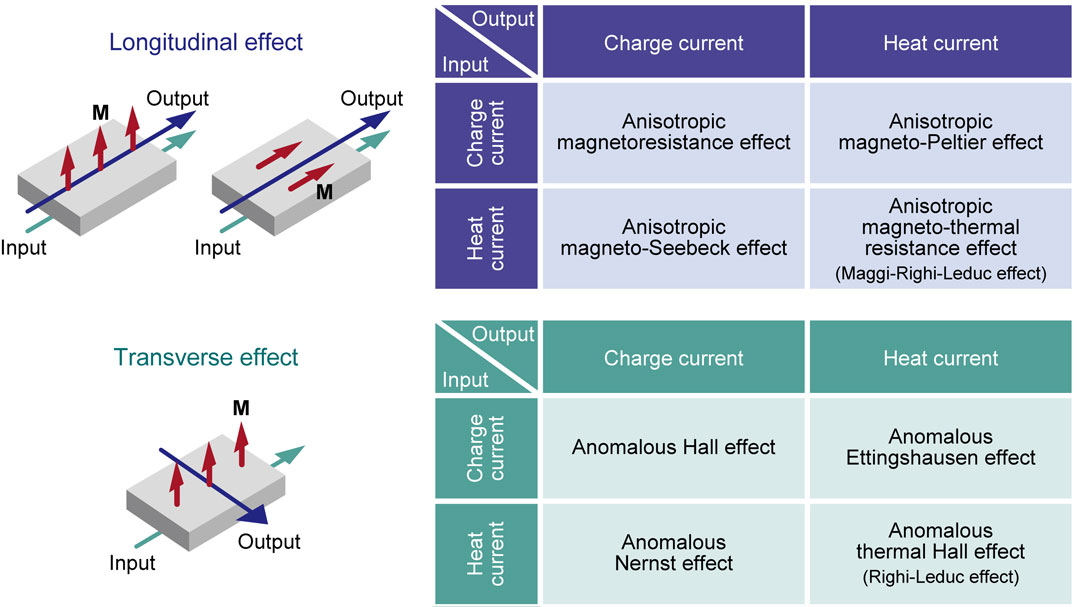
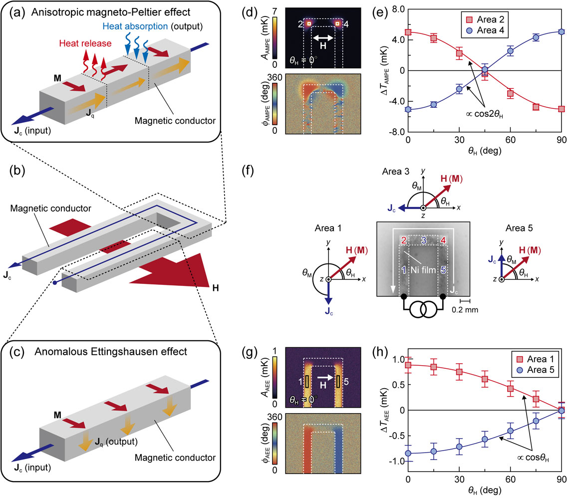
As summarized in Fig. 1, the conversion between charge and heat currents in magnetic materials is classified into two categories: “longitudinal effect” and “transverse effect”, in which the output current is generated in the direction parallel and perpendicular to the input current, respectively. The most well-known longitudinal electric transport phenomenon is the anisotropic magnetoresistance (AMR) effect, where the electrical resistivity changes with the relative angle θM between the M direction and the input current.13) In isotropic magnetic materials, the AMR obeys the following equation:
| \begin{equation}
\rho(\theta_{\text{M}}) = \rho_{\bot} + (\rho_{\|} - \rho_{\bot})\cos^{2}\theta_{\text{M}},
\end{equation}
| [1] |
where ρ
|| (ρ
⊥) is the resistivity when
M is parallel (perpendicular) to the input charge current. On the other hand, the most well-known transverse electric transport phenomenon is the anomalous Hall effect (AHE), where the charge current is bent in the direction perpendicular to
M.
14) In a similar manner to these phenomena, the thermoelectric conversion properties also depend on the
M direction in magnetic materials (
Fig. 1).
2.1. Longitudinal magneto-thermoelectric effects.
The longitudinal thermoelectric effects in magnetic materials are called the anisotropic magneto-Seebeck effect (AMSE) and the anisotropic magneto-Peltier effect (AMPE), where the Seebeck and Peltier coefficients depend on θM, respectively.15)–29) The θM dependence of the Seebeck coefficient S is similar to that of the AMR; if the magnetic material is isotropic, the symmetry of S is expressed as
| \begin{equation}
S(\theta_{\text{M}}) = S_{\bot} + (S_{\|} - S_{\bot})\cos^{2}\theta_{\text{M}},
\end{equation}
| [2] |
where
S|| (
S⊥) is the Seebeck coefficient when
M is parallel (perpendicular) to the input heat current. The AMSE has been observed in various magnetic materials and nanostructures. Such observations and the Onsager reciprocal relation (Π =
ST with Π being the Peltier coefficient) indicate the existence of the AMPE.
23) The direct observation of the temperature modulation induced by the AMPE, reported in 2018,
25) revealed the unconventional thermoelectric conversion functionalities of this phenomenon. For example, the AMPE enables reconfigurable electronic cooling/heating in a single material without junction structures, which cannot be realized if only the conventional Peltier effect is used.
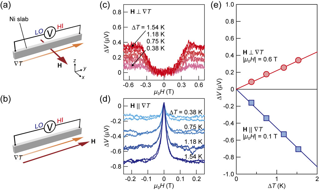
Figure 2 shows an example of the experimental results of the AMSE in a polycrystalline Ni slab with a rectangular shape.25) The electric voltage between the ends of the Ni slab was measured at room temperature with applying a temperature gradient ∇T along the y direction and H (with the magnitude H) in the direction perpendicular or parallel to the ∇T direction (Figs. 2(a) and 2(b)). Figures 2(c) and 2(d) show the voltage difference ΔV in the Ni slab as a function of H for various values of the temperature difference ΔT, where ΔV was obtained by removing the offset due to the H-independent thermopower. The ΔV signals exhibit clear H-even dependence; when H ⊥ ∇T (H || ∇T), the magnitude of ΔV increases (decreases) with increasing |H| and the field-induced change of ΔV is proportional to ΔT (Fig. 2(e)). Importantly, the ΔV signals in the H ⊥ ∇T (H || ∇T) configuration saturate at around μ0H = 0.4 T (0.1 T), which corresponds to the saturation field of the Ni slab (note that the difference in the saturation field is due to the shape magnetic anisotropy). This result indicates that the behavior of ΔV is determined by M, not H. The H-even dependence of the thermopower is a feature of the AMSE (see Eq. [2] and note that the asymmetric field dependence of the Seebeck coefficient called the Umkehr effect30) is absent in isotropic polycrystalline materials). The anisotropy of the Seebeck coefficient in the Ni slab was estimated to be ∼3% at room temperature. As shown in the above example, the AMSE can be investigated simply by measuring the magnetic field dependence of the longitudinal thermopower. Since such measurements are well established, many experiments on the AMSE have been reported so far.
Meanwhile, the direct observation of the AMPE requires unconventional thermal measurement techniques. In 2018, we realized the observation of the temperature modulation induced by the AMPE by using the active infrared emission microscopy technique called lock-in thermography (LIT).25),31),32) In the experiments of thermoelectric effects based on the LIT, the spatial distribution of infrared radiation thermally emitted from the surface of a sample is measured using an infrared camera while applying a square-wave-modulated AC charge current Jc with the amplitude Jc, frequency f, and zero DC offset to the sample. The thermal images oscillating with the same frequency as the input charge current are extracted through Fourier analysis. The contribution of the thermoelectric effects (∝ Jc) can be separated from the Joule-heating background (∝ Jc2) by extracting the first harmonic response of the thermal images, because the Joule heating generated in this condition is constant with time. As a result of the Fourier analysis, the obtained thermal images are transformed into the lock-in amplitude A and phase ϕ images, which show the distributions of the magnitude and sign of the current-induced temperature modulation, respectively. The ϕ image also includes the information on the time delay of the temperature modulation due to thermal diffusion.
The heat release and absorption induced by the AMPE appear on the boundaries between the areas with different θM values, even in the absence of junction structures. One of the simple ways to create such boundaries is to form a non-uniform magnetization configuration, as illustrated in Fig. 3(a). However, non-uniform magnetization configurations are not suitable for systematic measurements because it is difficult to change the magnetization distribution with high controllability. Therefore, the temperature modulation induced by the AMPE has been observed mainly in uniformly magnetized U-shaped materials, where a charge current is applied along the U-shaped structure (Fig. 3(b)). This configuration also leads to the non-uniform θM distribution; the AMPE-induced temperature modulation appears around the corners of the U-shaped structure, that is, the regions between the area satisfying M ⊥ Jc and the area satisfying M || Jc. Figure 3(d) shows an example of the experimental results of the AMPE in a polycrystalline Ni film with a U-shaped structure, measured by the LIT technique.28) The LIT images were measured while applying H in the x-y plane at an azimuthal angle θH from the +x direction (Fig. 3(f)). The pure AMPE contribution was separated from other thermoelectric contributions by measuring the dependence of the LIT images on the sign and/or angle of the magnetic field.25),28) When θH = 0°, we observed clear temperature-modulation signals appearing predominantly around the corners (areas 2 and 4 in Fig. 3(f)) of the U-shaped structure. The sign of the temperature modulation on the area 2 is opposite to that on the area 4 because of the lock-in phase difference of ∼180°. We also confirmed that the sign of the AMPE signal is reversed at θH = 90° and the signal disappears at θH = 45°; the θH dependence of the AMPE signals follows the cos 2θH symmetry (Fig. 3(e)). This behavior is consistent with Eq. [2] based on the trigonometric relations between θM and θH. As demonstrated here, the AMPE enables thermoelectric cooling and heating in a single material without junction structures. Owing to the absence of junctions, the thermoelectric output of the AMPE can be enhanced by constructing simple thermopile structures26) and reconfigured by changing the shape of the magnetic materials or the magnetization configuration. These characteristics provide new concepts in thermal management technologies for electronic and spintronic devices.
Because the thermoelectric performance of the AMSE/AMPE is still very low compared with conventional thermoelectric devices, it is necessary to find or develop magnetic materials with large anisotropy of the Seebeck/Peltier coefficient. To improve the thermoelectric performance, the AMSE/AMPE was measured not only in Ni but also in various ferromagnetic metals.25),29) Although Ni exhibits clear anisotropy of the Seebeck/Peltier coefficient, the AMSE/AMPE in polycrystalline Fe was observed to be negligibly small. This behavior is quantitatively reproduced by first-principles-based Boltzmann transport calculations, which clarified that spin-flip electron transitions due to the spin-orbit interaction are the key mechanism in the AMSE/AMPE.27) The magnitude of the AMSE/AMPE signals in Ni95Pt5 and Ni95Pd5 was found to be larger than that in pure Ni; the anisotropy of the Seebeck/Peltier coefficient of Ni95Pt5 reaches ∼12%. However, the experiments also show that excess Pt and Pd contents decrease the anisotropy of the coefficient. These results indicate that the doping of heavy elements with strong spin-orbit interaction to ferromagnetic materials is useful for improving the thermoelectric conversion efficiency of the AMSE/AMPE, but the material dependence in such alloys is not simple and not fully understood. However, materials science studies to find magnetic materials that show large AMSE/AMPE are already in progress. In this vein, Masuda et al. predicted that several ferromagnetic ordered alloys exhibit very large anisotropy of the Seebeck/Peltier coefficient.27) The experimental demonstration of this prediction is desired.
2.2. Transverse magneto-thermoelectric effects.
The transverse thermoelectric effects in magnetic materials are called the anomalous Nernst effect (ANE)33)–44) and the anomalous Ettingshausen effect (AEE),45)–52) which are the thermoelectric analogues of the AHE. In the ANE (AEE), an input heat (charge) current induces a transverse charge (heat) current in the direction perpendicular to the M direction. The symmetries of the ANE and AEE are respectively expressed as46)
| \begin{equation}
\mathbf{j}_{\text{c,ANE}} = \sigma S_{\text{ANE}}(\mathbf{m} \times \nabla T),
\end{equation}
| [3] |
| \begin{equation}
\mathbf{j}_{\text{q,AEE}} = \sigma\Pi_{\text{AEE}}(\mathbf{m} \times \nabla V).
\end{equation}
| [4] |
(
jq,AEE) is the charge (heat) current density driven by the ANE (AEE),
m is the unit vector of
M,
SANE (Π
AEE) is the anomalous Nernst (Ettingshausen) coefficient, σ is the electrical conductivity, and ∇
T (∇
V) is the temperature gradient (electric field) applied to the magnetic material. The anomalous Nernst and Ettingshausen coefficients are related by
| \begin{equation}
\Pi_{\text{AEE}} = S_{\text{ANE}}T,
\end{equation}
| [5] |
which is the Onsager reciprocal relation for the transverse thermoelectric conversion in magnetic materials. Based on this symmetry, the ANE/AEE exhibits a convenient scaling law that is entirely different from that of the longitudinal thermoelectric effects. In the case of the ANE, the output voltage (power) can be increased simply by elongating the device length (enlarging the device area) perpendicular to the temperature gradient without forming a multitude of serial p-n junctions. Furthermore, the thermoelectric output of the ANE/AEE can be actively controlled through the manipulation of
M.
47),48),50) Thus, the ANE (AEE) has the potential to realize simple and versatile thermal energy harvesting or heat-current sensing (thermal energy management) applications. Although the primary studies on the ANE/AEE were conducted a long time ago,
53)–55) the number of studies was quite limited. However, the ANE has received renewed attention in spin caloritronics since the discovery of the SSE, and experimental methods to separate the SSE from the ANE have been investigated.
56),57) These developments have significantly promoted research on the ANE itself. In particular, since the observation of the giant ANE in magnetic topological materials in 2018,
39) physics and materials science researches have further accelerated and become a trending development in condensed matter physics. In contrast to the ANE, the AEE was investigated only in typical ferromagnetic metal slabs since the 1920s.
53)–55) This situation was changed by the LIT technique; in 2018, Seki
et al. reported the visualization of the AEE-induced temperature modulation in ferromagnetic FePt thin films.
45) Subsequently, the AEE has been observed in various materials in both bulk and film forms, where the U-shaped structure is often used to demonstrate the symmetry of the AEE (
Figs. 3(b) and
3(c)). An example of the AEE measurements using a Ni film is shown in
Figs. 3(g) and
3(h).
28) By using the LIT method, the AMPE and AEE can be measured simultaneously but can be separated from each other owing to the different symmetries.
25),28),29) In 2019, it was demonstrated that SmCo
5-type permanent magnets exhibit the large AEE.
49)
The ANE can be characterized by measuring the magnetic field dependence of the transverse thermopower in magnetic materials. Following Eq. [3], the ANE thermopower exhibits the odd dependence on the magnetization direction, that is, the H-odd dependence. In contrast to isotropic bulk materials, ANE measurements for thin films are performed in two different configurations due to the huge difference between the in-plane and out-of-plane dimensions. One configuration is the in-plane magnetized (IM) configuration, where H (∇T) is applied along the in-plane (out-of-plane) direction (Fig. 4(a)). The IM configuration is suitable for thermal energy harvesting and heat sensing applications because ANE-based thermoelectric generation can be realized simply by forming films onto heat sources. In contrast, it is difficult to estimate SANE quantitatively in the IM configuration because of the difficulty in estimating the temperature difference between the top and bottom of thin films.57) The other configuration is the perpendicularly magnetized (PM) configuration, where H (∇T) is applied along the out-of-plane (in-plane) direction (Fig. 4(b)). The PM configuration is widely used for the quantitative estimation of SANE, although it often requires a large magnetic field to align M of films along the out-of-plane direction.
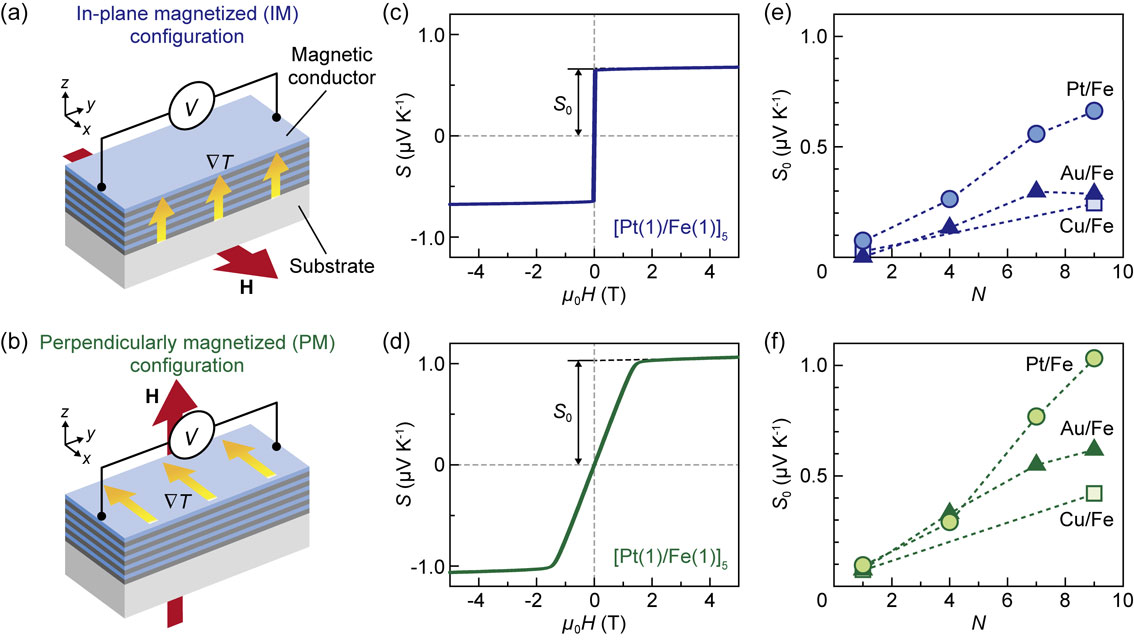
Figure 4 shows an example of the experimental results of the ANE in multilayer films comprising alternately stacked ferromagnetic and nonmagnetic metals.37) Here, the multilayer film can be regarded as a single effective magnetic material. Figures 4(c) and 4(d) show the μ0H dependence of the transverse thermopower S in a Pt/Fe multilayer film formed on a single-crystalline Gd3Ga5O12 (111) substrate in the IM and PM configurations, respectively. S is defined as (V/ΔT)(Lz/Ly) in the IM configuration and (V/ΔT)(Lx/Ly) in the PM configuration, where V is the voltage between the ends of the film, ΔT is the temperature difference between the ends of the sample including the substrate, and Lx,y,z is the length of the sample along the x, y, and z directions. The S values exhibit clear H-odd dependence and saturate when M is aligned along H, indicating that the ANE provides the dominant contribution to the transverse thermopower and that the field-induced ordinary Nernst effect is negligibly small. The ANE-driven transverse thermopower S0 can be extracted by extrapolating the S data in the high field region to zero field. Note that S0 ≠ SANE in the IM configuration because of the difference in the thermal conductivities between the film and substrate, while S0 = SANE in the PM configuration because of the same temperature difference in the film and substrate.
For practical applications of the ANE, it is important to find and develop magnetic materials with large SANE. In general, SANE can be divided into two components as42),49)
| \begin{equation}
S_{\text{ANE}} = \rho_{xx}\alpha_{xy} + \rho_{xy}\alpha_{xx},
\end{equation}
| [6] |
where ρ
xx (ρ
xy) is the diagonal (off-diagonal) component of the electrical resistivity tensor and α
xx (α
xy) is the diagonal (off-diagonal) component of the thermoelectric conductivity tensor. The second term on the right-hand side of
Eq. [6] originates from the AHE of the longitudinal carrier flow induced by the Seebeck effect. The first term originates from the intrinsic ANE, as α
xy directly converts ∇
T into a transverse electric field. A recent trend in improving
SANE is to find materials with large α
xy, in which the Berry curvature of the electronic bands near the Fermi level plays an essential role. Materials with topological band structure,
e.g., Co-based Heusler alloys, show large values of α
xy due to their large Berry curvature, which in turn lead to large
SANE values of 6–8 µV K
−1 at room temperature.
39)–41),44) The large ANE/AEE in SmCo
5-type permanent magnets has also been discussed in terms of the intrinsic mechanism; the experimental results are well reproduced by first-principles calculations, in which the intrinsic band structure and the chemical potential shift due to carrier doping were taken into account.
49),52) Another strategy for enhancing the ANE/AEE is to optimize the magnetic multilayer structures. As shown in
Figs. 4(e) and
4(f), the ANE in alternately stacked ferromagnetic metal/nonmagnetic metal multilayers was found to be enhanced by increasing the number of interfaces while keeping the total thickness constant. Although the enhancement of the ANE in multilayers seems to be a universal trend,
37),58)–60) the microscopic mechanism is not yet clarified. As discussed above, not only investigations of bulk transport properties but also multilayer design and interface engineering are essential in the studies of the ANE/AEE.
3. Conversion between spin and heat currents
In the field of spin caloritronics, various conversion phenomena between spin and heat currents have been discovered and investigated. The principles of such thermo-spin effects are conceptually different from the magneto-thermoelectric effects summarized in Sec. 2. In this section, we first review the definition of spin currents, followed by a summary of the basic behaviors and symmetries of typical thermo-spin effects.
3.1. Definition of spin current.
The charge current density jc is defined by the continuity equation for the charge density ρ as
| \begin{equation}
\frac{d\rho}{dt} = - \nabla \cdot \mathbf{j}_{\text{c}},
\end{equation}
| [7] |
where
t is time. This equation expresses the conservation of electron charge. In a similar manner, the spin current density
js is defined by the continuity equation for the magnetization
M as
| \begin{equation}
\frac{d\mathbf{M}}{dt} = - \gamma \nabla \cdot \mathbf{j}_{\text{s}} + \mathbf{T},
\end{equation}
| [8] |
which expresses the conservation of angular momentum.
3) Here, γ is the gyromagnetic ratio and
M includes not only the macroscopic spontaneous magnetization but also nonequilibrium components.
Equations [7] and
[8] indicate that a spin current transports magnetic moments or angular momentum, whereas a charge current transports electron charge. In contrast to the charge current, which is a conserved flow, the spin angular momentum dissipates into, for example, the lattice system, and the spin current is a non-conserved flow that disappears within a certain distance in a certain time. Thus, the right-hand side of
Eq. [8] contains the spin relaxation term
T. On a sufficiently short length scale for spin relaxation to be negligible, the spin current can be approximated as a conserved flow. Therefore, spin current physics has progressed rapidly with the development of nanotechnology that enables the construction of devices smaller than the spin relaxation length. The spin current is a second-order tensor quantity containing two degrees of freedom, namely, a spatial component (the direction in which the spin current flows) and a spin polarization component. However, the spin current can be treated as a vector quantity when the quantization axis of the spin is fixed (note that the operator ∇ on the right-hand side of
Eq. [8] acts on the spatial component). The spin current can be carried by conduction carriers with spin angular momenta, such as conduction electrons,
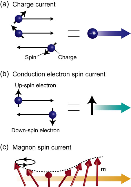
61),62) magnons or spin waves,
63),64) and spinons.
65) Hereafter, we focus on spin-current transport phenomena driven by conduction electrons and magnons, because they are the central foci of spintronics and spin caloritronics.
3.1.1. Conduction electron spin current.
When an external force, such as an electric field, is applied to metals or semiconductors, a nonequilibrium charge current is driven by conduction electrons on the Fermi surface. In a similar way, spins can be carried by conduction electrons acted on by an external force; the conduction electron spin current exists only in electric conductors. Assuming that the spin quantization axis is fixed, the charge current Jc and conduction electron spin current Js are respectively expressed as
| \begin{equation}
\mathbf{J}_{\text{c}} = e(\mathbf{J}_{\uparrow} + \mathbf{J}_{\downarrow}),
\end{equation}
| [9] |
| \begin{equation}
\mathbf{J}_{\text{s}} = \frac{\hbar}{2}(\mathbf{J}_{\uparrow} - \mathbf{J}_{\downarrow}),
\end{equation}
| [10] |
where
J↑ (
J↓) is the up-spin (down-spin) electron flow, −
e (
e > 0) is the electron charge, and
ħ/2 is the electron spin angular momentum (
Figs. 5(a) and
5(b)). The conduction electron spin current is often expressed in the same unit as the charge current by multiplying
Eq. [10] by 2
e/
ħ. When the magnitude of the up-spin electron flow is different from that of the down-spin electron flow, the conduction electron spin current becomes finite. In ferromagnetic metals, in which conduction electrons are spin-polarized, the charge current is always accompanied by a spin current,
i.e.,
Jc ≠ 0 means
Js ≠ 0. An important case is that the up- and down-spin electron flows have the same magnitude but opposite directions, as depicted in
Fig. 5(b). This situation leads to the generation of a pure spin current without any charge current,
i.e.,
Jc = 0 and
Js ≠ 0. The concept of the pure spin current plays a key role in various spin-transport phenomena and spintronic applications. Importantly, the conduction electron spin current can be injected into a nonmagnetic material using various methods including nonlocal spin-injection techniques
61),62) and the spin Hall effect (SHE).
62),66) The propagation length of the conduction electron spin current is called the spin diffusion length,
67) which is on the order of several nanometers in metals with strong spin relaxation or spin-orbit interaction, such as Pt. In contrast, the spin diffusion length can reach several hundreds of nanometers or several micrometers in conductors with weak spin-orbit interaction. With modern microfabrication technologies and thin-film deposition methods, vertical as well as lateral magnetic junction structures smaller than the spin diffusion length can be easily fabricated. Thus, the physics and behavior of the conduction electron spin current have already been investigated in detail in spintronics.
3.1.2. Magnon spin current.
A magnon is a quasiparticle of a spin wave, which is the collective dynamics of localized magnetic moments in magnetic materials. The magnon spin current is the flow of spin angular momentum carried by magnons (Fig. 5(c)). The magnon spin current can exist even in magnetic insulators with no conduction electrons, and is always a pure spin current because magnons have no charge. Magnons follow the Bose-Einstein statistics, and are thermally excited in magnetic materials at finite temperatures. However, a net flow of spin angular momentum, that is, the magnon spin current, is not generated under thermal equilibrium conditions because magnons with wavenumbers k and −k exist in equal numbers. The magnon spin current is generated when there is an imbalance in the numbers of k and −k magnons due to some external forces. The magnon dynamics can be obtained by solving the Landau-Lifshitz-Gilbert equation, which is the equation of motion for magnetic moments:
| \begin{equation}
\frac{d\mathbf{m}}{dt} = -\gamma \mathbf{m} \times \mathbf{H}_{\text{eff}} + \frac{\alpha}{M_{\text{s}}}\mathbf{m} \times \frac{d\mathbf{m}}{dt}.
\end{equation}
| [11] |
Here,
Heff is the effective magnetic field including the contributions of the external magnetic field, exchange interaction, magnetic dipole interaction, and magnetic anisotropy;
Ms is the saturation magnetization; and α is the Gilbert damping constant. The first term in
Eq. [11] describes the precession motion of
m around the
Heff direction, which can be derived from the Heisenberg equation of motion. The second term is the relaxation term phenomenologically introduced to direct
m in the
Heff direction. Due to the Gilbert damping, the magnon spin current is also a non-conserved quantity. However, the propagation length of the magnon spin current can reach the order of micrometers or millimeters in materials with small α values,
63),64) such as yttrium iron garnet Y
3Fe
5O
12 (YIG), which is significantly longer than the spin diffusion length of the conduction electron spin current. The magnon spin current is typically generated by nonlocal spin injection,
64) microwave-driven spin pumping,
63) and temperature-gradient-driven SSE.
10),12)
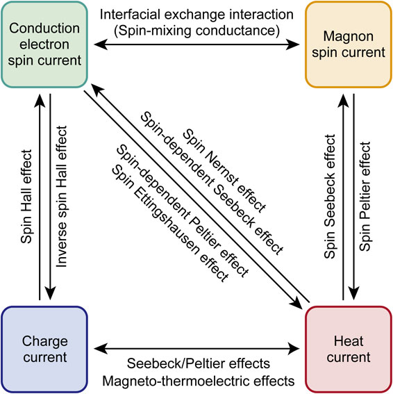
The magnon spin current in a magnetic material and the conduction electron spin current in a metal can be interconverted via the interfacial exchange interaction at the magnetic material/metal junction, which is known as the spin-mixing conductance68) (Fig. 6). The spin-mixing conductance enables the generation of magnon spin currents by injecting conduction electron spin currents into magnetic materials. Furthermore, it enables the detection of magnon spin currents by converting them into conduction electron spin currents. This interconversion is essential in the SSE and its Onsager reciprocal called the spin Peltier effect (SPE), discussed in Sec. 3.3.
3.2. Spin-dependent Seebeck and Peltier effects: Thermo-spin conversion based on conduction electron transport.
Let us recall the longitudinal electron transport in a conductor. The charge current density jc and heat current density jq are driven by the electrochemical potential gradient ∇μ and temperature gradient ∇T. The linear-response transport can be expressed as
| \begin{equation}
\begin{pmatrix}
\mathbf{j}_{\text{c}}\\
\mathbf{j}_{\text{q}}
\end{pmatrix}
=
\begin{pmatrix}
L_{11} & L_{12}\\
L_{21} & L_{22}
\end{pmatrix}\begin{pmatrix}
-\nabla \mu /e\\
-\nabla T
\end{pmatrix}
,
\end{equation}
| [12] |
where the magneto-thermoelectric effects are not described explicitly. In general, the Onsager reciprocal relation holds between the off-diagonal components of the transport coefficient matrix
L12 and
L21, which correspond to the Seebeck and Peltier effects, respectively.
The conduction electron spin current (with the density js) extends the electron transport phenomena. The transport phenomena in ferromagnetic conductors are often represented by up- and down-spin electron flows when the spin quantization axis is fixed. Here, not only the electrical conductivity and (electronic) thermal conductivity but also the Seebeck and Peltier coefficients exhibit spin dependence. For example, the electrical conductivity for up-spin electrons σ↑ is different from that for down-spin electrons σ↓ in ferromagnetic conductors. The driving forces in the spin-dependent electron transport are the spin-dependent electrochemical potential gradient ∇μ↑,↓ and ∇T, and the transport equation is expressed as
| \begin{equation}
\begin{pmatrix}
\mathbf{j}_{\text{c}}\\
\mathbf{j}_{\text{s}}\\
\mathbf{j}_{\text{q}}
\end{pmatrix}
=
\begin{pmatrix}
M_{11} & M_{12} & M_{13}\\
M_{21} & M_{22} & M_{23}\\
M_{31} & M_{32} & M_{33}
\end{pmatrix}\begin{pmatrix}
-\nabla (\mu_{\uparrow} + \mu_{\downarrow})/e\\
-\nabla (\mu_{\uparrow} - \mu_{\downarrow})/e\\
-\nabla T
\end{pmatrix}
,
\end{equation}
| [13] |
where −∇(μ
↑ + μ
↓)/
e corresponds to −∇μ/
e in
Eq. [12] and −∇(μ
↑ − μ
↓)/
e is the driving force due to the spin accumulation gradient. The heat current and conduction electron spin current are directly coupled if the off-diagonal components of
Eq. [13] are finite. For example, if the
M23 component is finite, the conduction electron spin current is generated by a temperature gradient. This phenomenon is known as the spin-dependent Seebeck effect because it is driven by the spin dependence of the Seebeck coefficient.
Equation [13] also holds the Onsager reciprocal relations, and various thermo-spin effects that correspond to each off-diagonal component exist. Many of these phenomena have already been observed experimentally. In 2010, Slachter
et al. used nonlocal spin-injection/detection methods in a lateral spin-valve structure and successfully observed the spin accumulation induced by the temperature difference between ferromagnetic/paramagnetic metal interfaces.
69) This is the first direct detection of the spin-dependent Seebeck effect. In 2011, Le Breton
et al. demonstrated temperature-gradient-induced spin injection into Si via a tunnel junction, which is called the Seebeck spin tunneling, in a ferromagnetic metal/oxide/Si junction system.
70) In 2012, Flipse
et al. observed the spin-dependent Peltier effect, the reciprocal of the spin-dependent Seebeck effect, in a nanopillar spin-valve device consisting of two ferromagnetic metal layers separated by a nonmagnetic metal.
71) Subsequently, Dejene
et al. reported the observation of a nonequilibrium temperature difference between up- and down-spin electrons, called spin heat accumulation, in a similar nanopillar device.
72) The spin-heat current conversion phenomena described in
Eq. [13] appear only in itinerant electron systems. Their mechanisms are completely different from those of the SSE and SPE, as described in the next subsection.
3.3. Spin Seebeck and Peltier effects: Thermo-spin conversion based on magnon transport.
The rapid development of spin caloritronics was triggered by the discovery of the SSE in which a spin current is generated as a result of a temperature gradient applied to a junction system comprising a magnetic material and a conductor. Because the first experiment on the SSE reported in 2008 was performed using a junction of a ferromagnetic metal (Ni81Fe19) and a paramagnetic metal (Pt),9) the SSE was initially discussed in terms of spin transport by conduction electrons, i.e., the aforementioned spin-dependent Seebeck effect, which occurs only in metals and semiconductors.73) However, it was experimentally demonstrated in 2010 that the SSE occurs in a magnetic insulator in which transport by conduction electrons is completely frozen.10),12) These experiments upset the conventional interpretation and revealed that the SSE originates from thermally excited magnon transport, because magnons can carry spin currents even in insulators.74)–80) Since the discovery of the SSE in magnetic insulators, the experimental techniques and theoretical understanding of this phenomenon have developed dramatically. Most of the recent SSE experiments were performed using magnetic insulators because the insulator-based systems allow us to obtain a relatively large heat-spin current conversion capability and to separate the contribution of the conduction-electron-driven magneto-thermoelectric effects from the magnon-spin-current contribution, enabling systematic and reliable investigation of the SSE.81) Considering the difference in the driving carriers between the SSE and the spin-dependent Seebeck effect, it may be expected that the former would be referred to as “magnon Seebeck effect” and the latter as “spin Seebeck effect”. However, as mentioned above, the SSE experiment was reported earlier than the observation of the spin-dependent Seebeck effect by Slachter et al. In addition, the term “spin Seebeck effect” and the experimental method in Ref. 9 were already widely used in 2010 when the direct observation of the spin-dependent Seebeck effect was reported. Thus, the spin-caloritronics community has decided to continue to refer to the magnon-driven thermo-spin conversion as the SSE, while the conduction-electron-driven thermo-spin conversion is distinguished from the SSE by calling it the spin-dependent Seebeck effect.6) Although the terminologies of the thermo-spin effects may be confusing because of the historical reasons, the SSE and the spin-dependent Seebeck effect are completely different phenomena. The same situation also applies to the magnon-driven SPE and the conduction-electron-driven spin-dependent Peltier effect (Fig. 6).
Here, the basic mechanism and behavior of the SSE are summarized. A typical system used for measuring the SSE is a junction structure consisting of a ferrimagnetic insulator YIG and a paramagnetic metal Pt. When ∇T is applied to YIG, a magnon spin current is generated along the gradient due to the thermally excited dynamics of localized magnetic moments (Fig. 7(a)). The magnon spin current in YIG is converted into a conduction electron spin current with the spatial direction Js and the spin polarization vector $\boldsymbol{\sigma}$ in the Pt layer via the spin-mixing conductance at the Pt/YIG interface, where Js is normal to the Pt/YIG interface plane and $\boldsymbol{\sigma}$ is parallel to M of YIG. This conduction electron spin current in the Pt layer is then converted by the strong spin-orbit interaction into the charge current Jc satisfying the following symmetry:
| \begin{equation}
\mathbf{J}_{\text{c}} \propto \boldsymbol{\sigma} \times \mathbf{J}_{\text{s}}.
\end{equation}
| [14] |
This spin-to-charge current conversion is called the inverse spin Hall effect (ISHE), while the conversion of a charge current into a conduction electron spin current via the spin-orbit interaction is called the spin Hall effect (SHE) (
Fig. 6).
66) Because the ISHE enables spin currents to be detected as voltage signals, it is extensively used to measure spin current phenomena. The symmetry of the ISHE causes the SSE thermopower to be generated in the direction perpendicular to ∇
T and
M; the SSE can hence work as a transverse thermoelectric generator.
81),82) In SSE experiments, the metallic layer must be a thin film with a thickness comparable to the spin diffusion length for efficient conversion from spin currents into voltage signals. In contrast, both bulk and thin film materials can be used as the magnetic insulator layer. Because the magnitude of the SSE-induced spin current depends on the propagation length of sub-thermal magnons, the ISHE voltage due to the SSE increases with increasing the thickness of the magnetic insulator layer and saturates at a thickness of several micrometers in single-crystalline YIG.
83)–85) As discussed above, the combination of the SSE with the ISHE enables transverse thermoelectric generation using insulators, which cannot be realized with conventional thermoelectric effects.

A typical temperature-dependent behavior of the SSE-induced transverse thermopower, i.e., the ISHE voltage induced by the SSE, is shown in Fig. 7(c).86) The sample system used in this experiment is a junction comprising a single-crystalline YIG slab and a Pt thin film. The SSE thermopower appears at temperatures lower than the Curie temperature of YIG and disappears at absolute zero temperature. The temperature dependence of the SSE thermopower is completely different from the magnetization curve of YIG (compare Fig. 7(b) and 7(c)). When single-crystalline YIG is used, the SSE thermopower increases with decreasing temperature and exhibits a peak at ∼30 K. The temperature at which the thermopower reaches its maximum is comparable to that at which the thermal conductivity of the single-crystalline YIG becomes maximum, where the thermal conductivity of YIG is determined mainly by phonon transport. Therefore, the steep peak signal may be related to the phonon drag effect on the SSE.87),88) There is also another argument that the low-temperature enhancement of the SSE thermopower is determined not only by the phonon drag effect but also by the enhancement of the magnon propagation length because the temperature dependences of the SSE thermopower and thermal conductivity differ at temperatures higher than the peak temperature. Although YIG is still most widely used in spin caloritronics, the SSE has been observed in various materials including ferro(ferri)magnetic, paramagnetic,89) antiferromagnetic,90),91) multiferroic,92) and quantum spin materials,65) indicating that the SSE is a universal transport phenomenon appearing in a wide variety of materials.
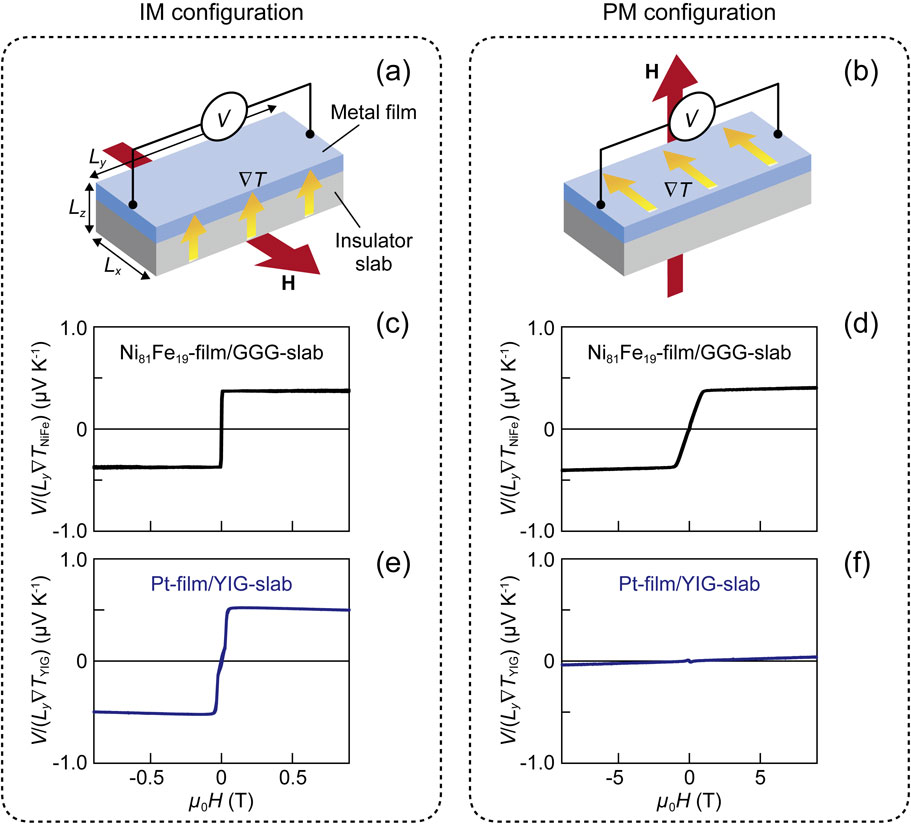
The symmetry of the SSE thermopower is similar to but different from that of the ANE thermopower. The SSE can be separated from the ANE by comparing the transverse thermopower in the IM configuration (Fig. 8(a)) and the PM configurations (Fig. 8(b)).56),57) As shown above, in the IM configuration, both the SSE and ANE exhibit the transverse thermopower of which the sign is reversed by reversing M. In contrast, in the PM configuration, the SSE thermopower disappears due to the symmetry of the ISHE (see Eq. [14] and note that $\mathbf{J}_{\text{s}}\parallel \boldsymbol{\sigma}$ in the PM configuration), while the ANE thermopower can appear because the ∇T, M, and inter-electrode directions are at right angles to one another. In fact, an isotropic ferromagnetic metal film was shown to exhibit isotropic ANE thermopower in the IM and PM configurations (Figs. 8(c) and 8(d)), while the Pt/YIG system exhibits no thermopower in the PM configuration, except for the small contribution from the ordinary Nernst effect in the Pt layer (Figs. 8(e) and 8(f)). This comparison confirms that the SSE is irrelevant to the ANE induced by the magnetic proximity effect93) near the Pt/YIG interface.
The Onsager reciprocal of the SSE is the SPE, in which a heat current is generated as a result of a spin current (Fig. 6). It was first experimentally observed in 2014 by Flipse et al., who also used Pt/YIG junction systems.94) As schematically illustrated in Fig. 7(d), the SPE appears through the inverse process of the SSE. When Jc is applied to the Pt film, a conduction electron spin current is generated in the direction of the film thickness by the SHE, and the spin accumulation occurs near the Pt/YIG interface. The spin accumulation is polarized in the direction that satisfies the following relationship:66)
| \begin{equation}
\mathbf{J}_{\text{s}} \propto \boldsymbol{\sigma} \times \mathbf{J}_{\text{c}}.
\end{equation}
| [15] |
This spin accumulation is converted into a magnon spin current in YIG via the spin-mixing conductance. The heat current generation due to the magnon spin current is the SPE. When
$\boldsymbol{\sigma}$ in the Pt layer is parallel or antiparallel to
M of YIG, the amplitude of the magnetic moment precession in YIG changes owing to the transfer of spin angular momentum, which changes the number of magnons. An increase (decrease) in the number of magnons corresponds to the high (low) effective temperature of the magnon system. Therefore, the temperature near the Pt/YIG interface is changed by the nonequilibrium state induced by the spin current injection. On the other hand, when
$\boldsymbol{\sigma}$ and
M are orthogonal, no temperature change appears. The heat current
Jq generated by the SPE thus obeys the symmetry
| \begin{equation}
\mathbf{J}_{\text{q}} \propto (\boldsymbol{\sigma} \cdot \mathbf{M}) \mathbf{n},
\end{equation}
| [16] |
where
n is the normal vector of the magnetic material/conductor junction interface.
32)
Because the observation of the SPE requires highly sensitive and accurate temperature measurements for thin-film devices, it is more challenging than the SSE experiments. In fact, few experimental studies on the SPE were reported for several years after its discovery until the establishment of versatile measurement methods for the spin-current-induced temperature change. In 2016, we applied the LIT technique to the measurement of the SPE, and successfully visualized the spin-current-induced temperature change and its unique spatial distribution.32) The LIT method enables the measurement of the SPE with high temperature and spatial resolutions in a simple and versatile sample structure, which does not require micro/nanofabrication techniques. Based on the knowledge obtained from the LIT measurements, the SPE was subsequently observed by using a thermocouple sensor95) as well as a lock-in thermoreflectance method.96) Figure 7(e) displays an example of the direct measurement of the temperature change due to the SPE by attaching a thin thermocouple to the surface of a Pt-film/single-crystalline YIG junction system.95) This result indicates that the temperature change increases in proportion to the charge current applied to the Pt layer and that the sign of the temperature change is reversed in response to the magnetization reversal of YIG. It is also important to note that the temperature change signal is suppressed when a strong magnetic field is applied. This behavior results from the suppression of the thermal excitation of magnon spin currents due to the Zeeman gap under a strong magnetic field.83),95) Systematic studies on the SPE performed using various measurement techniques have led to the elucidation of its detailed behavior. Theoretical studies on the SPE have also been reported.97)–99)
4. Other spin-caloritronic phenomena
In Secs. 2 and 3, we discussed the magneto-thermoelectric and thermo-spin effects in magnetic materials and their simple junction structures. In addition to such simple systems, spin-caloritronic phenomena also appear in giant magnetoresistance (GMR) and tunneling magnetoresistance (TMR) devices, which form the core of spintronic technologies. In the GMR (TMR) device in which a nonmagnetic metal (insulator) film is sandwiched between two ferromagnetic metal films, the electrical resistivity is larger when the magnetization directions of the adjacent ferromagnetic layers are antiparallel than when they are parallel (Fig. 9). The switching of the magnetization configuration can be achieved by a magnetic field or spin injection. By utilizing this property, high-performance magnetic sensors and memories have been developed in spintronics, and many researchers are conducting materials science and device engineering studies to further improve the performance of the GMR and TMR devices.4),5) In such multilayer devices, not only the electrical resistivity but also the thermal conductivity100) and the Seebeck/Peltier coefficients101)–104) can change depending on whether the magnetization directions of the ferromagnetic layers are parallel or antiparallel. Improved thermoelectric conversion efficiency and thermal conductivity switching ratio may make the principles and technologies of spin caloritronics useful for the thermal management of electronic and spintronic devices.

All the thermo-spin effects introduced in Sec. 3 can be classified as the longitudinal effects because spin and heat currents flow parallel to each other. Recently, basic studies on the transverse thermo-spin effects have also been conducted. For example, in 2017, several groups reported the observation of the spin Nernst effect,105)–107) which is the thermal analogue of the SHE. In the spin Nernst effect, a conduction electron spin current is generated in nonmagnetic conductors via the spin-orbit interaction in the direction perpendicular to the applied heat current (Fig. 6). These experiments suggest the existence of the spin Ettingshausen effect, the reciprocal of the spin Nernst effect, and its direct observation is desired. As reviewed above, the development of novel phenomena, principles, and functionalities based on the interplay between spin, charge, and heat currents is still ongoing in spin caloritronics.
5. Conclusions
We have reviewed the thermoelectric effects unique to magnetic materials, i.e., the magneto-thermoelectric effects, and the conversion phenomena between spin and heat currents, i.e., the thermo-spin effects. Although only several examples of such phenomena are introduced in this Review, new principles and phenomena are discovered in spin caloritronics every year. The background to this rapid development lies in the fact that the 2 × 2 transport coefficient matrix representing charge and heat transport phenomena (Eq. [12]) is extended to the 3 × 3 matrix by including a spin current (Eq. [13]), which results in a significant increase in the variety of transport phenomena. Moreover, the introduction of other spin transport carriers, such as magnons, has brought about a wider variety of thermo-spin conversion phenomena. Research fields in which novel phenomena are discovered frequently are extremely rare and there is a significant amount of physics that remains unclear in spin caloritronics. The exploration of new principles has motivated numerous experimental and theoretical researchers to study spin-caloritronic phenomena.
What is the significance of spin caloritronics from the viewpoint of applications? One of the answers to this question is the utilization of novel functionalities provided by the spin degree of freedom, which cannot be realized with conventional thermal energy engineering and thermoelectric technologies. Employing the transport phenomena introduced in this Review, various thermoelectric generation and thermal management functionalities can be realized, including the following:
-
•
Magnetic-field-induced control of the sign and magnitude of thermopower,
-
•
Thermoelectric power generation and cooling using insulators,
-
•
Construction of simple thermoelectric conversion modules without using Π-shaped thermopile structures,
-
•
Enhancement of thermoelectric output by enlarging a lateral device area,
-
•
Electronic cooling by a single magnetic material without junction structures,
-
•
Reconfiguration of thermoelectric conversion characteristics by changing the shape of magnetic materials and their magnetization distribution,
-
•
Active control of heat current directions and distributions.
Currently, the thermoelectric conversion efficiency of the spin-caloritronic phenomena is much smaller than that of the conventional Seebeck and Peltier effects. However, both physics and materials science studies are still in the early stages of development, and further discovery of new principles and improvement of the thermoelectric/thermo-spin conversion efficiencies are expected in the future.
Acknowledgements
The experimental results shown in this Review were obtained from the collaboration with S. Daimon, R. Das, D. Hou, R. Iguchi, R. Itoh, X.-F. Jin, T. Kikkawa, T. Oyake, K. Oyanagi, Z. Qiu, E. Saitoh, T. Seki, J. Shiomi, Y. Shiomi, and K. Takanashi. The author thanks many collaborators and group members for valuable discussions and supports and R. Iguchi, T. Hirai, and R. Modak for preliminary reviews of the manuscript. This work was partially supported by CREST “Creation of Innovative Core Technologies for Nano-enabled Thermal Management” (JPMJCR17I1) and PRESTO “Phase Interfaces for Highly Efficient Energy Utilization” (JPMJPR12C1) from JST, Japan; Grant-in-Aid for Challenging Exploratory Research (26600067) and Grant-in-Aid for Scientific Research (A) (15H02012) from JSPS KAKENHI, Japan; and the NEC Corporation.
Notes
Edited by Hiroyuki SAKAKI, M.J.A.
Correspondence should be addressed: K. Uchida, Research Center for Magnetic and Spintronic Materials (CMSM), National Institute for Materials Science (NIMS), 1-2-1 Sengen, Tsukuba, Ibaraki 305-0047, Japan (e-mail: UCHIDA.Kenichi@nims.go.jp).
References
- 1) Ashcroft, N.W. and Mermin, N.D. (1976) Solid State Physics. Saunders College, Philadelphia.
- 2) Boona, S.R., Myers, R.C. and Heremans, J.P. (2014) Spin caloritronics. Energy Environ. Sci. 7, 885–910.
- 3) Maekawa, S., Saitoh, E., Valenzuela, S.O. and Kimura, T. (eds.) (2017) Spin Current (2nd edition). Oxford University Press, Oxford.
- 4) Bhatti, S., Sbiaa, R., Hirohata, A., Ohno, H., Fukami, S. and Piramanayagam, S.N. (2017) Spintronics based random access memory: A review. Mater. Today 20, 530–548.
- 5) Hirohata, A., Yamada, K., Nakatani, Y., Prejbeanu, I.L., Diény, B., Pirro, P. (2020) Review on spintronics: Principles and device applications. J. Magn. Magn. Mater. 509, 166711.
- 6) Bauer, G.E.W., Saitoh, E. and van Wees, B.J. (2012) Spin caloritronics. Nat. Mater. 11, 391–399.
- 7) Johnson, M. and Silsbee, R.H. (1987) Thermodynamic analysis of interfacial transport and of the thermomagnetoelectric system. Phys. Rev. B 35, 4959–4972.
- 8) Hatami, M., Bauer, G.E.W., Zhang, Q. and Kelly, P.J. (2007) Thermal spin-transfer torque in magnetoelectronic devices. Phys. Rev. Lett. 99, 066603.
- 9) Uchida, K., Takahashi, S., Harii, K., Ieda, J., Koshibae, W., Ando, K. (2008) Observation of the spin Seebeck effect. Nature 455, 778–781.
- 10) Uchida, K., Xiao, J., Adachi, H., Ohe, J., Takahashi, S., Ieda, J. (2010) Spin Seebeck insulator. Nat. Mater. 9, 894–897.
- 11) Jaworski, C.M., Yang, J., Mack, S., Awschalom, D.D., Heremans, J.P. and Myers, R.C. (2010) Observation of the spin-Seebeck effect in a ferromagnetic semiconductor. Nat. Mater. 9, 898–903.
- 12) Uchida, K., Adachi, H., Ota, T., Nakayama, H., Maekawa, S. and Saitoh, E. (2010) Observation of longitudinal spin-Seebeck effect in magnetic insulators. Appl. Phys. Lett. 97, 172505.
- 13) McGuire, T. and Potter, R. (1975) Anisotropic magnetoresistance in ferromagnetic 3d alloys. IEEE Trans. Magn. 11, 1018–1038.
- 14) Nagaosa, N., Sinova, J., Onoda, S., MacDonald, A.H. and Ong, N.P. (2010) Anomalous Hall effect. Rev. Mod. Phys. 82, 1539–1592.
- 15) Jan, J.-P. (1957) Galvanomagnetic and thermomagnetic effects in metals. In Solid State Physics Vol. 5 (eds. Seitz, F. and Turnbull, D.). Academic Press, New York, pp. 1–96.
- 16) Grannemann, G. and Berger, L. (1976) Magnon-drag Peltier effect in a Ni-Cu alloy. Phys. Rev. B 13, 2072–2079.
- 17) Wegrowe, J.-E., Nguyen, Q.A., Al-Barki, M., Dayen, J.F., Wade, T.L. and Drouhin, H.J. (2006) Anisotropic magnetothermopower: Contribution of interband relaxation. Phys. Rev. B 73, 134422.
- 18) Avery, A.D., Sultan, R., Bassett, D., Wei, D. and Zink, B.L. (2011) Thermopower and resistivity in ferromagnetic thin films near room temperature. Phys. Rev. B 83, 100401(R).
- 19) Mitdank, R., Handwerg, M., Steinweg, C., Töllner, W., Daub, M., Nielsch, K. (2012) Enhanced magneto-thermoelectric power factor of a 70 nm Ni-nanowire. J. Appl. Phys. 111, 104320.
- 20) Avery, A.D., Pufall, M.R. and Zink, B.L. (2012) Observation of the planar Nernst effect in permalloy and nickel thin films with in-plane thermal gradients. Phys. Rev. Lett. 109, 196602.
- 21) Avery, A.D., Pufall, M.R. and Zink, B.L. (2012) Determining the planar Nernst effect from magnetic-field-dependent thermopower and resistance in nickel and permalloy thin films. Phys. Rev. B 86, 184408.
- 22) Schmid, M., Srichandan, S., Meier, D., Kuschel, T., Schmalhorst, J.-M., Vogel, M. (2013) Transverse spin Seebeck effect versus anomalous and planar Nernst effects in permalloy thin films. Phys. Rev. Lett. 111, 187201.
- 23) Das, K.S., Dejene, F.K., van Wees, B.J. and Vera-Marun, I.J. (2016) Anisotropic Hanle line shape via magnetothermoelectric phenomena. Phys. Rev. B 94, 180403(R).
- 24) Reimer, O., Meier, D., Bovender, M., Helmich, L., Dreessen, J.-O., Krieft, J. (2017) Quantitative separation of the anisotropic magnetothermopower and planar Nernst effect by the rotation of an in-plane thermal gradient. Sci. Rep. 7, 40586.
- 25) Uchida, K., Daimon, S., Iguchi, R. and Saitoh, E. (2018) Observation of anisotropic magneto-Peltier effect in nickel. Nature 558, 95–99.
- 26) Das, R. and Uchida, K. (2019) Thermopile based on anisotropic magneto-Peltier effect. Appl. Phys. Lett. 114, 082401.
- 27) Masuda, K., Uchida, K., Iguchi, R. and Miura, Y. (2019) First-principles study of anisotropic magneto-Peltier effect. Phys. Rev. B 99, 104406.
- 28) Das, R., Iguchi, R. and Uchida, K. (2019) Systematic investigation of anisotropic magneto-Peltier effect and anomalous Ettingshausen effect in Ni thin films. Phys. Rev. Appl. 11, 034022.
- 29) Miura, A., Iguchi, R., Seki, T., Takanashi, K. and Uchida, K. (2020) Spin-mediated charge-to-heat current conversion phenomena in ferromagnetic binary alloys. Phys. Rev. Mater. 4, 034409.
- 30) Wolfe, R. and Smith, G.E. (1963) Experimental verification of the Kelvin relation of thermoelectricity in a magnetic field. Phys. Rev. 129, 1086–1087.
- 31) Breitenstein, O., Warta, W. and Langenkamp, M. (2010) Lock-in Thermography: Basics and Use for Evaluating Electronic Devices and Materials Introduction. Springer, Berlin/Heidelberg.
- 32) Daimon, S., Iguchi, R., Hioki, T., Saitoh, E. and Uchida, K. (2016) Thermal imaging of spin Peltier effect. Nat. Commun. 7, 13754.
- 33) Miyasato, T., Abe, N., Fujii, T., Asamitsu, A., Onoda, S., Onose, Y. (2007) Crossover behavior of the anomalous Hall effect and anomalous Nernst effect in itinerant ferromagnets. Phys. Rev. Lett. 99, 086602.
- 34) Pu, Y., Chiba, D., Matsukura, F., Ohno, H. and Shi, J. (2008) Mott relation for anomalous Hall and Nernst effects in Ga1−xMnxAs ferromagnetic semiconductors. Phys. Rev. Lett. 101, 117208.
- 35) Mizuguchi, M., Ohata, S., Uchida, K., Saitoh, E. and Takanashi, K. (2012) Anomalous Nernst effect in an L10-ordered epitaxial FePt thin film. Appl. Phys. Express 5, 093002.
- 36) Sakuraba, Y., Hasegawa, K., Mizuguchi, M., Kubota, T., Mizukami, S., Miyazaki, T. (2013) Anomalous Nernst effect in L10-FePt/MnGa thermopiles for new thermoelectric applications. Appl. Phys. Express 6, 033003.
- 37) Uchida, K., Kikkawa, T., Seki, T., Oyake, T., Shiomi, J., Qiu, Z. (2015) Enhancement of anomalous Nernst effects in metallic multilayers free from proximity-induced magnetism. Phys. Rev. B 92, 094414.
- 38) Ikhlas, M., Tomita, T., Koretsune, T., Suzuki, M., Nishio-Hamane, D., Arita, R. (2017) Large anomalous Nernst effect at room temperature in a chiral antiferromagnet. Nat. Phys. 13, 1085–1090.
- 39) Sakai, A., Mizuta, Y.P., Nugroho, A.A., Sihombing, R., Koretsune, T., Suzuki, M. (2018) Giant anomalous Nernst effect and quantum-critical scaling in a ferromagnetic semimetal. Nat. Phys. 14, 1119–1124.
- 40) Reichlova, H., Schlitz, R., Beckert, S., Swekis, P., Markou, A., Chen, Y.C. (2018) Large anomalous Nernst effect in thin films of the Weyl semimetal Co2MnGa. Appl. Phys. Lett. 113, 212405.
- 41) Guin, S.N., Manna, K., Noky, J., Watzman, S.J., Fu, C., Kumar, N. (2019) Anomalous Nernst effect beyond the magnetization scaling relation in the ferromagnetic Heusler compound Co2MnGa. NPG Asia Mater. 11, 16.
- 42) Sakuraba, Y., Hyodo, K., Sakuma, A. and Mitani, S. (2020) Giant anomalous Nernst effect in the Co2MnAl1−xSix Heusler alloy induced by Fermi level tuning and atomic ordering. Phys. Rev. B 101, 134407.
- 43) Sakai, A., Minami, S., Koretsune, T., Chen, T., Higo, T., Wang, Y. (2020) Iron-based binary ferromagnets for transverse thermoelectric conversion. Nature 581, 53–57.
- 44) Sumida, K., Sakuraba, Y., Masuda, K., Kono, T., Kakoki, M., Goto, K. (2020) Spin-polarized Weyl cones and giant anomalous Nernst effect in ferromagnetic Heusler films. Commun. Mater. 1, 89.
- 45) Seki, T., Iguchi, R., Takanashi, K. and Uchida, K. (2018) Visualization of anomalous Ettingshausen effect in a ferromagnetic film: Direct evidence of different symmetry from spin Peltier effect. Appl. Phys. Lett. 112, 152403.
- 46) Seki, T., Iguchi, R., Takanashi, K. and Uchida, K. (2018) Relationship between anomalous Ettingshausen effect and anomalous Nernst effect in an FePt thin film. J. Phys. D Appl. Phys. 51, 254001.
- 47) Ota, S., Uchida, K., Iguchi, R., Van Thach, P., Awano, H. and Chiba, D. (2019) Strain-induced switching of heat current direction generated by magneto-thermoelectric effects. Sci. Rep. 9, 13197.
- 48) Nakayama, H., Hirai, T., Uzuhashi, J., Iguchi, R., Ohkubo, T., Koyama, T. (2019) Electric-field-induced on-off switching of anomalous Ettingshausen effect in ultrathin Co films. Appl. Phys. Express 12, 123003.
- 49) Miura, A., Sepehri-Amin, H., Masuda, K., Tsuchiura, H., Miura, Y., Iguchi, R. (2019) Observation of anomalous Ettingshausen effect and large transverse thermoelectric conductivity in permanent magnets. Appl. Phys. Lett. 115, 222403.
- 50) Wang, J., Takahashi, Y.K. and Uchida, K. (2020) Magneto-optical painting of heat current. Nat. Commun. 11, 2.
- 51) Xu, L., Li, X., Lu, X., Collignon, C., Fu, H., Koo, J. (2020) Finite-temperature violation of the anomalous transverse Wiedemann-Franz law. Sci. Adv. 6, eaaz3522.
- 52) Miura, A., Masuda, K., Hirai, T., Iguchi, R., Seki, T., Miura, Y. (2020) High-temperature dependence of anomalous Ettingshausen effect in SmCo5-type permanent magnets. Appl. Phys. Lett. 117, 082408.
- 53) Bridgman, P.W. (1924) The connections between the four transverse galvanomagnetic and thermomagnetic phenomena. Phys. Rev. 24, 644–651.
- 54) Hall, E.H. (1925) Measurement of the four magnetic transverse effects. Phys. Rev. 26, 820–840.
- 55) Butler, E. Jr. and Pugh, E. (1940) Galvano- and thermomagnetic phenomena in iron and nickel. Phys. Rev. 57, 916–921.
- 56) Kikkawa, T., Uchida, K., Shiomi, Y., Qiu, Z., Hou, D., Tian, D. (2013) Longitudinal spin Seebeck effect free from the proximity Nernst effect. Phys. Rev. Lett. 110, 067207.
- 57) Kikkawa, T., Uchida, K., Daimon, S., Shiomi, Y., Adachi, H., Qiu, Z. (2013) Separation of longitudinal spin Seebeck effect from anomalous Nernst effect: Determination of origin of transverse thermoelectric voltage in metal/insulator junctions. Phys. Rev. B 88, 214403.
- 58) Fang, C., Wan, C.H., Yuan, Z.H., Huang, L., Zhang, X., Wu, H. (2016) Scaling relation between anomalous Nernst and Hall effect in [Pt/Co]n multilayers. Phys. Rev. B 93, 054420.
- 59) Ramos, R., Kikkawa, T., Anadon, A., Lucas, I., Niizeki, T., Uchida, K. (2019) Interface-induced anomalous Nernst effect in Fe3O4/Pt-based heterostructures. Appl. Phys. Lett. 114, 113902.
- 60) Seki, T., Sakuraba, Y., Masuda, K., Miura, A., Tsujikawa, M., Uchida, K. (2021) Enhancement of the anomalous Nernst effect in Ni/Pt superlattices. Phys. Rev. B 103, L020402.
- 61) Jedema, F.J., Filip, A.T. and van Wees, B.J. (2001) Electrical spin injection and accumulation at room temperature in an all-metal mesoscopic spin valve. Nature 410, 345–348.
- 62) Kimura, T., Otani, Y., Sato, T., Takahashi, S. and Maekawa, S. (2007) Room-temperature reversible spin Hall effect. Phys. Rev. Lett. 98, 156601.
- 63) Kajiwara, Y., Harii, K., Takahashi, S., Ohe, J., Uchida, K., Mizuguchi, M. (2010) Transmission of electrical signals by spin-wave interconversion in a magnetic insulator. Nature 464, 262–266.
- 64) Cornelissen, L.J., Liu, J., Duine, R.A., Ben Youssef, J. and van Wees, B.J. (2015) Long-distance transport of magnon spin information in a magnetic insulator at room temperature. Nat. Phys. 11, 1022–1026.
- 65) Hirobe, D., Sato, M., Kawamata, T., Shiomi, Y., Uchida, K., Iguchi, R. (2017) One-dimensional spinon spin currents. Nat. Phys. 13, 30–34.
- 66) Sinova, J., Valenzuela, S.O., Wunderlich, J., Back, C.H. and Jungwirth, T. (2015) Spin Hall effects. Rev. Mod. Phys. 87, 1213–1259.
- 67) Bass, J. and Pratt, W.P. Jr. (2007) Spin-diffusion lengths in metals and alloys, and spin-flipping at metal/metal interfaces: An experimentalist’s critical review. J. Phys. Condens. Matter 19, 183201.
- 68) Tserkovnyak, Y., Brataas, A. and Bauer, G.E.W. (2002) Enhanced Gilbert damping in thin ferromagnetic films. Phys. Rev. Lett. 88, 117601.
- 69) Slachter, A., Bakker, F.L., Adam, J.-P. and van Wees, B.J. (2010) Thermally driven spin injection from a ferromagnet into a non-magnetic metal. Nat. Phys. 6, 879–882.
- 70) Le Breton, J.-C., Sharma, S., Saito, H., Yuasa, S. and Jansen, R. (2011) Thermal spin current from a ferromagnet to silicon by Seebeck spin tunneling. Nature 475, 82–85.
- 71) Flipse, J., Bakker, F.L., Slachter, A., Dejene, F.K. and van Wees, B.J. (2012) Direct observation of the spin-dependent Peltier effect. Nat. Nanotechnol. 7, 166–168.
- 72) Dejene, F.K., Flipse, J., Bauer, G.E.W. and van Wees, B.J. (2013) Spin heat accumulation and spin-dependent temperatures in nanopillar spin valves. Nat. Phys. 9, 636–639.
- 73) Uchida, K., Takahashi, S., Ieda, J., Harii, K., Ikeda, K., Koshibae, W. (2009) Phenomenological analysis for spin-Seebeck effect in metallic magnets. J. Appl. Phys. 105, 07C908.
- 74) Xiao, J., Bauer, G.E.W., Uchida, K., Saitoh, E. and Maekawa, S. (2010) Theory of magnon-driven spin Seebeck effect. Phys. Rev. B 81, 214418.
- 75) Adachi, H., Ohe, J., Takahashi, S. and Maekawa, S. (2011) Linear-response theory of spin Seebeck effect in ferromagnetic insulators. Phys. Rev. B 83, 094410.
- 76) Adachi, H., Uchida, K., Saitoh, E. and Maekawa, S. (2013) Theory of the spin Seebeck effect. Rep. Prog. Phys. 76, 036501.
- 77) Hoffman, S., Sato, K. and Tserkovnyak, Y. (2013) Landau-Lifshitz theory of the longitudinal spin Seebeck effect. Phys. Rev. B 88, 064408.
- 78) Rezende, S.M., Rodríguez-Suárez, R.L., Cunha, R.O., Rodrigues, A.R., Machado, F.L.A., Fonseca Guerra, G.A. (2014) Magnon spin-current theory for the longitudinal spin-Seebeck effect. Phys. Rev. B 89, 014416.
- 79) Rezende, S.M., Rodríguez-Suárez, R.L., Cunha, R.O., López Ortiz, J.C. and Azevedo, A. (2016) Bulk magnon spin current theory for the longitudinal spin Seebeck effect. J. Magn. Magn. Mater. 400, 171–177.
- 80) Cornelissen, L.J., Peters, K.J.H., Bauer, G.E.W., Duine, R.A. and van Wees, B.J. (2016) Magnon spin transport driven by the magnon chemical potential in a magnetic insulator. Phys. Rev. B 94, 014412.
- 81) Uchida, K., Adachi, H., Kikkawa, T., Kirihara, A., Ishida, M., Yorozu, S. (2016) Thermoelectric generation based on spin Seebeck effects. Proc. IEEE 104, 1946–1973.
- 82) Kirihara, A., Uchida, K., Kajiwara, Y., Ishida, M., Nakamura, Y., Manako, T. (2012) Spin-current-driven thermoelectric coating. Nat. Mater. 11, 686–689.
- 83) Kikkawa, T., Uchida, K., Daimon, S., Qiu, Z., Shiomi, Y. and Saitoh, E. (2015) Critical suppression of spin Seebeck effect by magnetic fields. Phys. Rev. B 92, 064413.
- 84) Kehlberger, A., Ritzmann, U., Hinzke, D., Guo, E.-J., Cramer, J., Jakob, G. (2015) Length scale of the spin Seebeck effect. Phys. Rev. Lett. 115, 096602.
- 85) Daimon, S., Uchida, K., Ujiie, N., Hattori, Y., Tsuboi, R. and Saitoh, E. (2020) Thickness dependence of spin Peltier effect visualized by thermal imaging technique. Appl. Phys. Express 13, 103001.
- 86) Iguchi, R., Uchida, K., Daimon, S. and Saitoh, E. (2017) Concomitant enhancement of the longitudinal spin Seebeck effect and the thermal conductivity in a Pt/YIG/Pt system at low temperatures. Phys. Rev. B 95, 174401.
- 87) Adachi, H., Uchida, K., Saitoh, E., Ohe, J., Takahashi, S. and Maekawa, S. (2010) Gigantic enhancement of spin Seebeck effect by phonon drag. Appl. Phys. Lett. 97, 252506.
- 88) Jaworski, C.M., Yang, J., Mack, S., Awschalom, D.D., Myers, R.C. and Heremans, J.P. (2011) Spin-Seebeck effect: A phonon driven spin distribution. Phys. Rev. Lett. 106, 186601.
- 89) Wu, S.M., Pearson, J.E. and Bhattacharya, A. (2015) Paramagnetic spin Seebeck effect. Phys. Rev. Lett. 114, 186602.
- 90) Seki, S., Ideue, T., Kubota, M., Kozuka, Y., Takagi, R., Nakamura, M. (2015) Thermal generation of spin current in an antiferromagnet. Phys. Rev. Lett. 115, 266601.
- 91) Wu, S.M., Zhang, W., Amit, K.C., Borisov, P., Pearson, J.E., Jiang, J.S. (2016) Antiferromagnetic spin Seebeck effect. Phys. Rev. Lett. 116, 097204.
- 92) Takagi, R., Tokunaga, Y., Ideue, T., Taguchi, Y., Tokura, Y. and Seki, S. (2016) Thermal generation of spin current in a multiferroic helimagnet. APL Mater. 4, 032502.
- 93) Huang, S.Y., Fan, X., Qu, D., Chen, Y.P., Wang, W.G., Wu, J. (2012) Transport magnetic proximity effects in platinum. Phys. Rev. Lett. 109, 107204.
- 94) Flipse, J., Dejene, F.K., Wagenaar, D., Bauer, G.E.W., Ben Youssef, J. and van Wees, B.J. (2014) Observation of the spin Peltier effect for magnetic insulators. Phys. Rev. Lett. 113, 027601.
- 95) Itoh, R., Iguchi, R., Daimon, S., Oyanagi, K., Uchida, K. and Saitoh, E. (2017) Magnetic-field-induced decrease of the spin Peltier effect in Pt/Y3Fe5O12 system at room temperature. Phys. Rev. B 96, 184422.
- 96) Yamazaki, T., Iguchi, R., Ohkubo, T., Nagano, H. and Uchida, K. (2020) Transient response of the spin Peltier effect revealed by lock-in thermoreflectance measurements. Phys. Rev. B 101, 020415(R).
- 97) Basso, V., Ferraro, E., Magni, A., Sola, A., Kuepferling, M. and Pasquale, M. (2016) Nonequilibrium thermodynamics of the spin Seebeck and spin Peltier effects. Phys. Rev. B 93, 184421.
- 98) Ohnuma, Y., Matsuo, M. and Maekawa, S. (2017) Theory of the spin Peltier effect. Phys. Rev. B 96, 134412.
- 99) Costa, S.S. and Sampaio, L.C. (2020) Magnon theory for the spin Peltier effect. J. Phys. D Appl. Phys. 53, 355001.
- 100) Kimling, J., Wilson, R.B., Rott, K., Kimling, J., Reiss, G. and Cahill, D.G. (2015) Spin-dependent thermal transport perpendicular to the planes of Co/Cu multilayers. Phys. Rev. B 91, 144405.
- 101) Gravier, L., Serrano-Guisan, S. and Ansermet, J.P. (2005) Spin-dependent Peltier effect in Co/Cu multilayer nanowires. J. Appl. Phys. 97, 10C501.
- 102) Shan, J., Dejene, F.K., Leutenantsmeyer, J.C., Flipse, J., Münzenberg, M. and van Wees, B.J. (2015) Comparison of the magneto-Peltier and magneto-Seebeck effects in magnetic tunnel junctions. Phys. Rev. B 92, 020414(R).
- 103) Kuschel, T., Czerner, M., Walowski, J., Thomas, A., Schumacher, H.W., Reiss, G. (2019) Tunnel magneto-Seebeck effect. J. Phys. D Appl. Phys. 52, 133001.
- 104) Nakayama, H., Nakatani, T., Iguchi, R., Seki, T. and Uchida, K. (2019) Direct observation of magneto-Peltier effect in current-in-plane giant magnetoresistive spin valve. Appl. Phys. Lett. 115, 092406.
- 105) Meyer, S., Chen, Y.-T., Wimmer, S., Althammer, M., Wimmer, T., Schlitz, R. (2017) Observation of the spin Nernst effect. Nat. Mater. 16, 977–981.
- 106) Sheng, P., Sakuraba, Y., Lau, Y.-C., Takahashi, S., Mitani, S. and Hayashi, M. (2017) The spin Nernst effect in tungsten. Sci. Adv. 3, e1701503.
- 107) Kim, D.-J., Jeon, C.-Y., Choi, J.-G., Lee, J.W., Surabhi, S., Jeong, J.-R. (2017) Observation of transverse spin Nernst magnetoresistance induced by thermal spin current in ferromagnet/non-magnet bilayers. Nat. Commun. 8, 1400.
Profile

Ken-ichi Uchida was born in Kanagawa Prefecture, Japan in 1986. He obtained his B. Eng. (2008) and M. Sc. Eng. (2009) degrees from Keio University, Yokohama, Japan, and his Ph. D. (2012) degree from Tohoku University, Sendai, Japan. He was an assistant professor (2012–2014) and an associate professor (2014–2016) at Institute for Materials Research, Tohoku University. He has been a group leader of Spin Caloritronics Group, Research Center for Magnetic and Spintronic Materials, National Institute for Materials Science in Japan (since 2016) and a cross-appointment professor at Institute for Materials Research, Tohoku University (since 2019). He has worked mainly on spintronics, spin caloritronics, and thermoelectrics. His important achievements include the discovery of the spin Seebeck effect in metals (2008) and insulators (2010), discovery of spin current generation from sound waves (2011) and surface plasmons (2015), thermal imaging of the spin Peltier effect (2016), and first direct observation of the anisotropic magneto-Peltier effect (2018) and magneto-Thomson effect (2020). He received many awards including JSPS Ikushi Prize from Japan Society for the Promotion of Science (2011), Young Scientists’ Prize, Commendation for Science and Technology from Ministry of Education, Culture, Sports, Science and Technology (2013), Gottfried Wagener Prize from German Innovation Award (2014), Nagase Prize from Frontier Salon Foundation (2014), Yamato Scientific Award from Yamato Scientific Co., Ltd. (2014), NISTEP Award from National Institute of Science and Technology Policy (2015), Funai Research Award from The Funai Foundation for Information Technology (2019), Marubun Research Encouragement Award from Marubun Research Promotion Foundation (2019), and JSPS Prize from Japan Society for the Promotion of Science (2020).