Abstract
Background: We encountered five patients of post-THA femoral stem fracture without femoral fracture. The purpose of this study was to elucidate the mechanism underlying the observed femoral stem fractures.
Methods: We performed an assessment of the cement mantle using plain radiographic images. We analyzed the state of the fractured stems and fractured surfaces of these stems during the revision surgery. Additionally, we replicated the same prosthesis support conditions that were present around the fractured stems and verified the analytic results by using mechanical tests (bending test, fatigue test), finite element method (FEM) analysis and material tests. Bending tests were performed at a loading rate of 5 mm/min. In contrast, for fatigue testing, the bending tests were repeated under a loading of 2300 N at a frequency of 5 Hz. The cemented distal portions of the fractured stems were all firmly attached, but the proximal portions were unsupported. During these simulation tests, the distal portion was fixed at a distance of 80 mm from the center of the femoral head using a 36-mm femoral head.
Results: The plain radiographic images at the time of the stem fracture showed that radiolucencies were observed in all patients around the proximal regions of the stem, although good fixation was obtained at the distal portions. We could easily remove the parts of the stem proximal to the fracture site in all patients during surgery, while the distal parts were solidly cemented. Examination of the fracture surfaces showed that the fracture origin was on the lateral surface in the middle of the stem. The middle portion of the stem bent during the compression-bending test, with this position corresponding to the fracture site. FEM analysis showed that the area corresponding to the stem fracture origin was the same as predicted from examining the fractured surface.
Conclusion: Bending test and FEM showed that only the distal part of Co–Cr alloy stem was firmly fixed and the internal stress was concentrated at a point just proximal to the fixed part. Therefore, this point coincided with the fractured point of the stem.
Introduction
The number of THA surgeries performed in Japan in 2013 exceeded 110,000.1,2 Therefore, we considered that the number of patients requiring revision of THA will also inevitably increase.
The results of an epidemiology study by Bozic et al.3 indicate that among the factors that lead to the revision of THA, implant loosening accounted for 24.7%, whereas peri-implant fractures accounted for 18.7%. Post-THA femoral stem fracture is a rare complication, and its incidence has been reported to range between 0.23% and 0.67%.4–6 Fractures of the femoral stem usually occur near the femoral neck. However, few reports on fractures occurred closer to the center of the stem.7 We encountered five patients in which a post-THA femoral stem fracture occurred in the absence of a femoral fracture.
The purpose of this study was to elucidate the mechanism underlying femoral stem fractures, which resulted in revision of THA. For this purpose, we analyzed patient background, method of stem implantation, postoperative radiographic images, shapes, and characteristics of the implant material, and fracture surfaces of the fractured stem. Additionally, we replicated the same prosthesis support conditions that were present around the fractured stems and verified the analysis results using mechanical tests, finite element method (FEM) analysis, and material tests.
Materials and Methods
Patient information
We reviewed 1,134 patients who had undergone their first THA using a cemented femoral stem (C-Prominent hip system: Teijin Nakashima medical, Japan) and an acetabular component between January 2003 and September 2015. Of the 1,134 patients, we included five patients who had suffered a stem fracture without a concomitant femoral fracture in this study.
Characterics of the C-Prominent hip system
The C-Prominent hip system is a stem shape that was developed to conform to the morphology of the medullary cavity in Japanese individuals. The femoral stem for the C-Prominent hip system was forged from a wrought cobalt–chromium (Co–Cr) alloy. The stem has a collar attached to the medial side and a modular femoral head made of Co–Cr alloy that is fixed by a taper lock (10/12 taper).
Surgery
The diagnosis prior to the initial THA was osteoarthritis of the hip in all patients. Additionally, factures also occurred on the left side in all patients. The initial THA was performed using an anterolateral approach (Hardinge approach).8 Preoperative planning involved using a two-dimensional template based on plain radiographic images, which showed frontal and lateral views. A femoral stem size ranging from 1 to 3 was used for revision surgery (Table 1).
Table1
Subject demographic and clinical characteristics
| Case no. |
Age(years) |
Sex |
Height(cm) |
Body weight(kg) |
BMI(kg/m2) |
Postoperative interval (months) |
Stem size(offset width in mm) |
Positioning angle(degrees) |
Cement grade |
| 1 |
61 |
Female |
145 |
66 |
31.4 |
46 |
2 (32.6) |
0 |
B |
| 2 |
53 |
Female |
150 |
62 |
27.6 |
73 |
2 (32.6) |
valgus 2 |
B |
| 3 |
70 |
Female |
152 |
77 |
33.3 |
120 |
1 (32.0) |
0 |
B |
| 4 |
63 |
Female |
153 |
48 |
20.5 |
81 |
2 (32.6) |
valgus 1 |
B |
| 5 |
57 |
Female |
147 |
63 |
29.2 |
122 |
3 (33.2) |
0 |
B |
The modular heads of the fractured stems all used a standard length neck, and the diameter of the femoral head measured 26 mm in all patients. The acetabular socket was made of an ultra-high molecular weight polyethylene with an attached titanium marker. From May 2011 onward, a highly cross-linked polyethylene was adopted at our institute. These patients underwent THA with sockets that were manufactured from non-cross-linked polyethylene. The femoral stem was inserted using a third generation cementing technique.9 Air bubbles within the cement were compressed and removed using suction. After pulse cleaning the femoral medullary cavity, the internal cavity was dried using suction. A plastic cement plug was inserted and cement was then injected using a cement gun.
Assessment of plain radiographs
We performed an assessment of the cement mantle immediately after surgery using plain radiographic images and graded the findings using the classification proposed by Barrack et al.10 The radiographic appearance of the initial cementing was graded on the immediate postoperative radiograph. Complete filling of the medullary cavity by cement, a so-called white-out at the cement–bone interface was graded A. Slight radiolucency of the cement–bone interface was defined as B. Radiolucency involving 50%–99% of the cement–bone interface or a defective or incomplete cement mantle was graded C. Radiolucency at the cement–bone interface of 100% in any projection, or a failure to fill the canal with cement such that the tip of the stem was not covered, was classified as D.
Implant assessment
The femoral stem for the C-Prominent hip system was forged from a wrought cobalt–chromium (Co–Cr) alloy. The stem has a collar attached to the medial side and a modular femoral head made of Co–Cr alloy that is fixed by a taper lock (10/12 taper). The femoral head diameter was 26 mm in all patients. The surface of the stem underwent surface treatment using shot blasting from the collar to the distal portion. Stem surface roughness was measured by arithmetic average roughness (Ra)=2 μm. The serial number of the stem was marked using high-energy density laser light.
Patients who suffered stem fractures were fitted with a larger stem size or a longer stem during revision surgery. Intraoperatively, we examined the fixation strength between the stem and cement and checked for the presence of findings that may have been associated with stem loosening. We also fenestrated the femur to allow the withdrawal of distal portion of the stem.
The fracture surfaces of the extracted femoral stems were examined using a scanning electron microscope (S-4800, Hitachi, Japan). We also analyzed plain radiographic images of the fractured stems to identify any potential casting defects, using an X-ray apparatus (MG325, Yxlon, Germany).
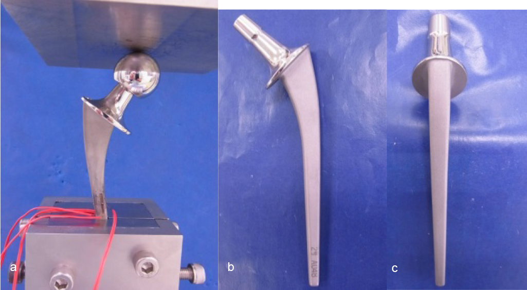
Stems generally fracture after shear stress to the central portion; therefore, we used a typical size-2 femoral stem and mechanical tests to reproduce these loading and fracture conditions. We performed the test using methods in accordance with the ISO7206-4 standards (fatigue strength testing of prosthetic hip stems). Bending tests were performed at a loading rate of 5 mm/min. In contrast, for fatigue testing, the bending tests were repeated under a loading of 2300 N at a frequency of 5 Hz. The cemented distal portions of the fractured stems were all firmly attached, but the proximal portions were unsupported. During these simulation tests, the distal portion was fixed at a distance of 80 mm from the center of the femoral head using a 36-mm femoral head. We used a universal testing machine (Servo Pulsar, EHF-LB10k-4LA, Shimadzu, Japan) to conduct these tests.
Next, to investigate the stress states during loading, we performed FEM analysis on the femoral stems. The stem was positioned at a valgus angle of 10° and placed at a posterior inclination of 9°. The test configuration also conformed to the ISO7204-4 standards and was performed under a simulated loading of 2,300 N. Young’s modulus of the Co–Cr alloy was set to 225 GPa, Poisson’s ratio to 0.3, and friction coefficient between the femoral head and the stem to 0.8. The site of assessment was 10 mm proximal to the site of fixation. Static simulation was performed using nonlinear analysis software MSC.Marc2010 (MSC software, USA).
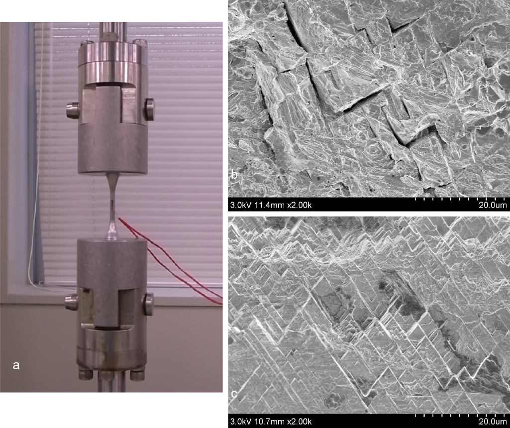
To perform a detailed consideration of the fractured surface of the Co–Cr alloy, we performed material tests using dumbbell test pieces with a cross-sectional area of 15.9 mm2. These tensile tests were performed at a pulling rate of 1 mm/min. Fatigue tests were also performed on dumbbell test pieces with repeated loading of 7,952 N at a frequency of 10 Hz. We then examined the fractured surfaces obtained during each test.
The present study was approved by the Bioethics Review Committees of Fujita Health University (HM17-284).
Results
Patients data
The stem fractures occurred between December 2009 and January 2016. Fractures occurred after a median period of 88.2 (46–122) months postoperatively. The mean age at the time of revision surgery was 60.8 (53–70) years, and the patients were all females. Mean height and mean body weight at the time of revision surgery were 149.4 cm (145–153 cm) and 63.2 kg (48–77 kg), respectively, and BMI values were 20.5–33.3 kg/m2.
Assessment of plain radiographs
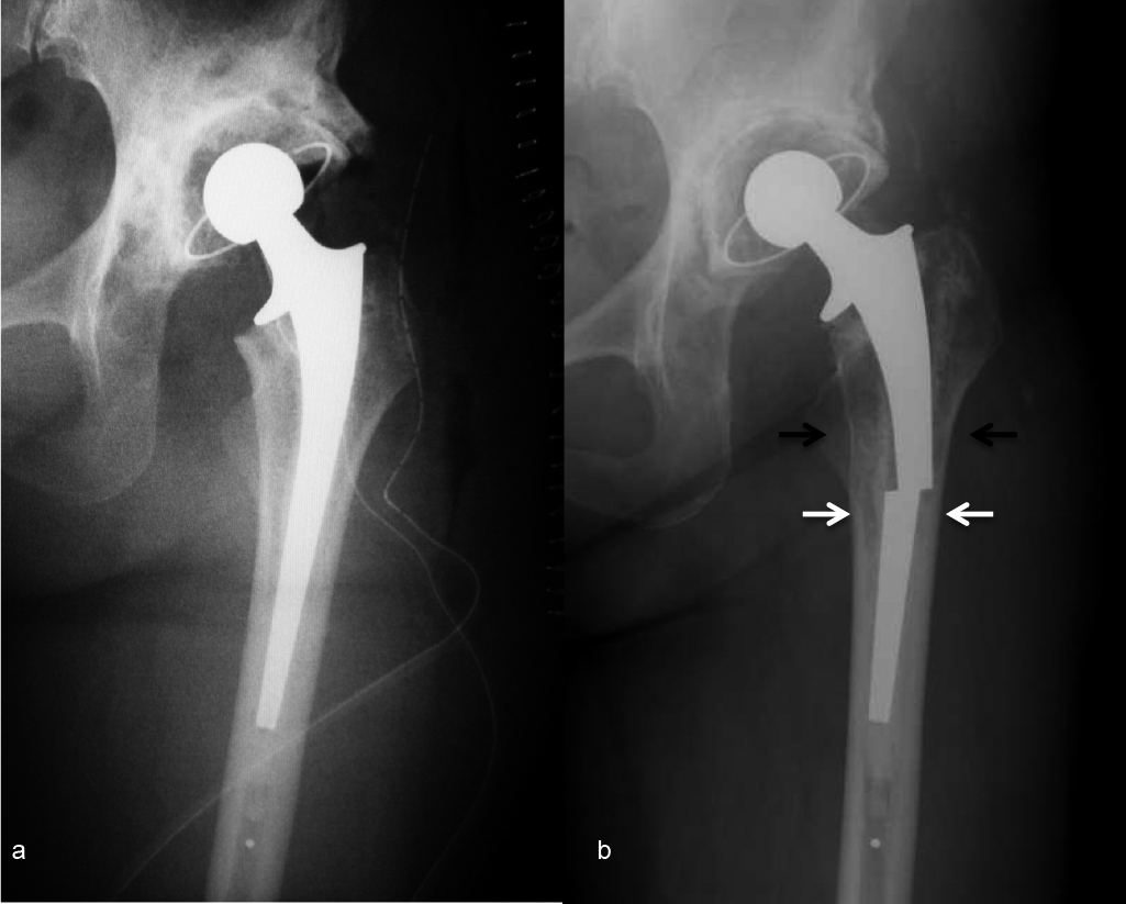
The assessment of the cement mantle on plain radiographic images taken immediately after surgery indicated grade B in all patients (Table 1). The plain radiographic images at the time of the stem fracture showed that radiolucencies were observed in all patients around the proximal regions of the stem, although good fixation was obtained at the distal portions. The radiographic images from patient 2 are shown in Figure 1. Radiolucencies were observed in the region surrounding the stem (Gruen zones 1, 7)11 in areas proximal to the stem fracture. Radiolucency of the bone distal to the fracture site was observed just near the fracture (Gruen zones 2, 6)11 (Figure 1).
We could easily remove the part of the stem proximal to the fracture site in all five patients during revision surgery, although the distal parts were solidly cemented. No wearing of the tapered part of the stem neck was evident, and no findings suggested metallosis.12 Patients 1 and 2 demonstrated loosening of the cemented acetabular cups, and we believe this represented osteolysis.13 No findings suggesting in the surgical field during the revision surgery.
Implant assessment
Examination of the fracture surfaces of the stems removed from all five patients during the revision surgery showed that the fracture origin was on the lateral surface in the middle of the stem. The fracture surface demonstrated a characteristic V-shape and a herringbone pattern, which resembled a series of overlapping rectangles placed at right angles to one another (Figure 2). Such a herringbone pattern is characteristic of the fracture surface of brittle materials.14
While examining the removed stems, we did not observe any instances of casting defects in plain radiographic images.
During the compression-bending test using the ISO7206-4 configuration, the central portion of the stem bent with this position corresponding to the fracture site. The stems did not bend or fracture during the fatigue tests. Further, we did not observe any changes in the stem when we increased the number of loading repetitions from the 500×104 required by the standards to 3,000×104 (Figure 3).
The distribution of von Mises stress determined through FEM analysis showed that the stress was the highest in the center of the stem, whereas tensile stress was distributed more laterally and compression stress was distributed more medially. In other words, the lateral part of the center of the stem was exposed to a maximum amount of tensile stress, with this area corresponding to the stem fracture origin that was predicted when examining the fractured surface (Figure 4).
The presence of a herringbone pattern was noted on the fracture surfaces of the dumbbell tensile test pieces in the material tests and particularly during the fatigue strength tests. Based on the above, we are able to interpret the cause of the herringbone pattern that is present on the fatigued fracture surface of materials containing Co–Cr alloys (Figure 5).
Discussion
Surgery
The C-Prominent hip system has been used in 1,134 individuals to date at our hospital. Of these, five patients sustained stem fractures that were not associated with femur fractures. The prevalence of stem fractures has been reported to be 0.44%,4–6 and our results are consistent with these findings. Generally, the risk factors for stem fracture include use of raw materials that may lead to the appearance of bubbles on the implant surface, poor stem positioning, selecting a stem too small in size, undergoing bilateral replacement, height of ≥180 cm and body weight of ≥81 kg, and poor cementation of the proximal part of the stem.5,7,15
The fractured stems of our patients were comparatively small at sizes 1, 2, 3. Considering that defects arose in patients with small stature who may be considered at a low risk of stem fracture, it may actually be necessary to select a stem that is of the maximum possible size for that patient. However, the thickness of the cement mantle must also be taken into consideration. Thus, we believe it is necessary to compromise and select a slightly smaller size of femoral stem.
Loosening and stem fracture
According to previous reports, the prevalence of loosening may vary based on the use of different cementing techniques during THA.16
We used a third generation cementing technique during surgery. There were no particular challenges that immediately arose after surgery. However, polyethylene wear debris and associated osteolysis were detected. This led to a loss of support appearing in the proximal part of the stem, which we believe then spread even further. All patients who suffered from fractures had sockets that were manufactured from non-cross-linked polyethylene.
In other words, we consider that the loosening of the proximal stem caused the distal, cemented portion to assume weight-bearing. This created a large lever arm, which became a bending point. Thus, through continued repetitive loading, this resulted in the stem fractures.
Stem material and fracture
Analysis of the fracture surface revealed that a herringbone pattern was observed on both the fractured stems removed during the operation and the fractured ones occurring during the material tests. We presumed that this occurred because of the specific fracture mechanism of Co–Cr alloys. Normally, we observe a striated pattern when we examine the fractured surface of a titanium (Ti) alloy that has undergone fatigue failure.17,18 It is possible that these differences in the features of the implant material may be associated with the breakage of the stem in the absence of a femoral bone fracture. Nevertheless, further studies on the metal properties of Co–Cr are needed to verify this.
Reports indicate that bubbles may occur at the implant surface owing to the metal properties of the Co–Cr alloy used for the femoral stems, which could become the fracture origin.19 During the present tests, we found no casting defect when we performed plain radiograph analysis of the fractured stems.
We have also not seen any results suggesting that the fracture origin was the part of the stem that underwent surface treatment or the part that had been marked with the serial number.
Analysis by in vitro test
The fact that there was no fracture in the femoral stems during the fatigue and compression-bending test shows that the ISO7206-4 test configuration may underestimate the strength required for the smallest prostheses. Meanwhile, the central portion of the stem bent during the bending test, and this position corresponded to the fracture site. We believe that the fact that the lateral part of the center of the stem was subjected to the maximum tensile stress, as was revealed during FEM analysis, could explain why this part may become the fracture origin.
Based on the above, we considered that in the occurrence of proximal loosening and strong fixation of the distal part, the internal stress is concentrating at a point of 10 mm proximal to the fixed part. We believe it is highly likely that stem fractures occur because of further loading, such as minor trauma and routine, repeated weight-bearing.
Accordingly, when the postoperative plain radiographic images show loosening of the proximal stem, we believe that observation through diligent follow-up is required added to an adequate explanation to the patient of the likelihood of fracture.
Conclusion
Bending test and FEM showed that only the distal part of Co–Cr alloy stem was firmly fixed and the internal stress was concentrated at a point just proximal to the fixed part. Therefore, this point coincided with the fractured point of the stem.
References
- 1. United Nations Department of Economic and Social Affairs. World Population Prospects. The 2008 Revision. 2009. <http://www.un.org/esa/population/publications/wpp2008/wpp2008_highlights.> (Accessed Oct 24, 2017).
- 2. Yano Research Institute: 2014 nemban medeikaru baionikusu (jinko zoki) shijo no chuki yosoku to sannyu kigyo no tettei bunseki. (2014 Ed. Medical Bionics (artificial organs). Detailed analysis of medium-term market predictions and business entering the market—analysis of implants, extracorporeal circulation and related devices and materials by item); 2014 (in Japanese). <http://www.yano.co.jp/market_reports/C56107300>. (Accessed October 24, 2017).
- 3. Bozic KJ, Kurtz SM, Lau E, Ong K, Vail TP, Berry DJ. The epidemiology of revision total hip arthroplasty in the United States. J Bone Joint Surg Am 2009; 91: 128–133.
- 4. Carlsson AS, Gentz CF, Stenport J. Fracture of the femoral prosthesis in total hip replacement according to Charnley. Acta Orthop Scand 1977; 48: 650–655.
- 5. Charnley J. Fracture of femoral prosthesis in total hip replacement. A clinical study. Clin Orthop Relat Res 1975; 111: 105–120.
- 6. Heck DA, Partridge CM, Reuben JD, Lanzer WL, Lewis CG, Keating EM. Prosthetic component failures in hip arthroplasty surgery. J Arthroplasty 1995; 10: 575–580.
- 7. Woolson ST, Mibauer JP, Bobyn JD, Yue S, Maloney WJ. Fatigue fracture of a forged cobalt-chromium-molybdenum femoral component inserted with cement. A report of ten cases. J Bone Joint Surg Am 1997; 79: 1842–1848.
- 8. Hardinge K. The direct lateral approach to the hip. J Bone Joint Surg Br 1982; 64: 17–19.
- 9. Harris WH, McGann WA. Loosening of the femoral component after use of the medullary-plug cementing technique. Follow-up note with a minimum five-year follow-up. J Bone Joint Surg Am 1986; 68: 1064–1066.
- 10. Barrack RL, Mulroy RD Jr, Harris WH. Improved cementing techniques and femoral component loosening in young patients with hip arthroplasty. A 12-year radiographic review. J Bone Joint Surg Br 1992; 74: 385–389.
- 11. Gruen TA, McNeice GM, Amstutz HC. “Modes of failure” of cemented stem-type femoral components: a radiographic analysis of loosening. Clin Orthop Relat Res 1979; 141: 17–27.
- 12. Iida H, Kaneda E, Takada H, Uchida K, Kawanabe K, Nakamura T. Metallosis due to impingement between the socket and the femoral neck in a metal-on-metal bearing total hip prosthesis. J Bone Joint Surg Am 1999; 81: 400–403.
- 13. Goldring SR, Schiler AL, Roelke M, Rourke CM, O’Neil DA, Harris WH. The synovial-like membrane at the bone-cement interface in loose total hip replacement and its proposed role in bone lysis. J Bone Joint Surg Am 1983; 65: 575–584.
- 14. Iida K. Fundamentals to Fractography. Journal of High Pressure Institute of Japan 1973; 11: 275–284.
- 15. Wrobleski BM. Fracture stem in total hip replacement: a clinical review of 120 cases. Acta Orthop Scand 1982; 53: 279–284.
- 16. Mulroy RD Jr, Harris WH. The effect of improved cementing techniques on component loosening in total hip replacement. An 11-year radiographic review. J Bone Joint Surg Br 1990; 72: 757–760.
- 17. Nakamura T. Fundamental knowledge of metal fatigue. Journal of Japan Foundry Engineering Society 2007; 79: 58–69 (in Japanese).
- 18. Liebowitz H. Microscopic and macroscopic fundamentals. New York: Academic Press: 1968.
- 19. Galante JO. Cause of fracture of the femoral component in total hip replacement. J Bone Joint Surg Am 1980; 62: 670–673.