Abstract
In order to extract quantitative information on deep-sea benthic animals
(no. individuals or biomass in an area) using oblique video/photo images
taken by deep-sea submersible survey platforms, a new method was established
to estimate the imaged area of the seafloor from the oblique images. The
trapezoidal area appearing on the lower half of the screen was calculated
using underwater horizontal and vertical aperture angles of the camera, the
angle of incidence of the camera, and the camera-to-seafloor distance. The
incidence angle of the camera was obtained using the angles of vehicle pitch
and camera tilt, while the camera-to-seafloor distance was calculated from
the lens-to-vehicle bottom distance, horizontal distance of
lens-to-altimeter, and vehicle altitude. The areas estimated by the present
method from images taken by some submersible survey platforms were
comparable to those that were actually measured. With the above parameters,
and by focusing on the lower half of an image, our method can be used for
estimating the seafloor area from any oblique video/photo images taken by
any submersible survey platform. Thus, this method is useful for the
extraction of quantitative data on benthic animals from legacy oblique
video/photographs acquired by submersible survey platforms.
1. Introduction
Video and/or photo images taken by submersible survey platforms are helpful
in understanding biological, geological and topographic settings in the
deep-sea. In a biological study, these images are not just useful for
obtaining qualitative information such as the distribution of deep-sea
benthos, but also for obtaining quantitative information, such as abundance
(e.g. individual m-2) and biomass (e.g. mg m-2) (e.g. Ohta and Laubier, 1987; Fujikura et al., 1995, 1996, 2002). To date, various deep-sea
survey platforms with a variety of camera systems have been operated by
JAMSTEC ― dating back to the 1980s (Fujikura et al., 2008). Extraction of
quantitative information on deep-sea benthic animals in various regions,
using these the accumulated video/photo records, is necessary for
understanding long-term changes and obtaining baselines to assess the impact
of catastrophic events such as the 2011 Tōhoku earthquake (Seike et al., 2013) or the effects of deep-sea mineral mining (Collins et al., 2013).
Extraction of quantitative information (e.g. abundance or biomass) requires
information on the area of the seafloor that was imaged (e.g. m2). A down-facing camera mounted on a submersible, ROV or deep-towed camera system
is often used to estimate the area of the seafloor (e.g. Fujikura et al., 1995, 2002; Jones et al., 2007; Guinan et al., 2009). The area (S) appearing
in a downward-looking image can easily be estimated using the following
equation (see Figs.1a, b):
|
\begin{equation}
\mathrm{S} = 4 a^{2} \tan (\alpha/2) \tan (\beta/2)
\end{equation}
| (1) |
where
a is the distance from the camera lens to the seafloor, and
$\alpha $ and
$\beta $ are the vertical and horizontal aperture angles of the camera, respectively (
Jones et al., 2007). However, most of the video/photo images taken by JAMSTEC's submersible survey platforms are from forward-facing cameras, angled obliquely towards the seafloor (
Figs. 2a-d), and thus the above equation is not applicable.


In an image angled obliquely towards the seafloor (hereafter “oblique image” ), the seafloor appears in the image in a trapezoidal geometry, with
the imaged area expanding into the distance (i.e. the upper part of the
image). In a previous study, Rice et al. (1979, 1982) obtained area values from
oblique images for a quantitative study of deep-sea benthos, but their
images were taken by camera mounted on a bottom sledge, where
camera-to-seafloor distance and camera tilt angle are fixed. Unlike the
camera with the sledge, submersible survey platforms such as human occupied
vehicles (HOVs) and remotely-operated vehicles (ROVs) face the problem that
the angles of camera tilt and vehicle pitch vary significantly during
transects, which leads to significant fluctuations in the imaged area of the
seafloor. Previously, Chevaldonné and Jollivet (2003) estimated the imaged seafloor area from oblique images taken by deep-sea submersible survey platforms, but their equation can only be used for images where camera tilt is nearly vertical. In contrast, most images taken by JAMSTEC submersible
platforms have a relatively wide field of view with a much shallower tilt
angle of the cameras (Figs. 2b-d). In such cases, the depth of an image is
often infinite, making it impossible to apply the method of Chevaldonné and Jollivet (2003). Moreover, the upper half of images is always dark ― in
most cases due to insufficient illumination, which makes it difficult to
count, identify, and sometimes even to recognize the benthic animals. In
this paper, we report a new method to estimate the imaged area of the
seafloor from oblique images taken with a shallow camera tilt.
2. Methods
The present study estimated the area of only the lower half of each image
(Fig. 3a), because the incident point of the camera lens (C in
Figs. 3a, b), that determines the angle of incidence ($\theta$ in Fig. 3b), lies exactly in the middle of the image. The angle
of incidence ($\theta$) is a vital parameter to measure the area
from oblique images, and focusing only on the lower half (1/2) of an image,
below the middle point, makes the areal calculation easier than for the
whole area or for other portions (e.g. 1/3, 3/4). The method also can be
used on images with a much shallower tilt angle of the camera, where the
depth of the upper part of the image is often infinite. The upper half of
such images is often dark due to a lack of reflected light, and objects of
interest within it are often too small to be identified reliably.
Quantitative observations of only the lower half of each image enables
identification and accurate counting of animals as they are much closer to
the camera. (see Figs. 2a-d).

The necessary parameters for estimating the area of the lower half of the
screen image (i.e. the trapezoidal area of ABDE in Fig. 3b) were underwater vertical ($\alpha$) and horizontal
($\beta$) aperture angles of the camera, the angle of incidence of
the camera ($\theta$), and the camera-to-seafloor distance
(OH). The incidence angle of the camera ($\theta$) was
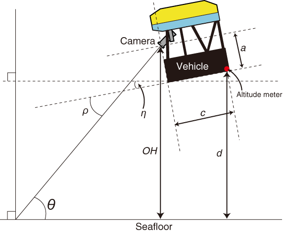
obtained using the angles of vehicle pitch ($\eta$) and camera tilt ($\rho$), while the camera-to-seafloor distance (OH) was calculated from
lens-to-vehicle bottom distance (a), horizontal distance of
lens-to-altimeter (c), and vehicle altitude, as measured by an
altitude meter (d). Among the necessary parameters,
$\alpha$, $\beta$, a, and c are vehicle-specific values and will vary depending on the submersible survey platform, while d, $\eta$ and $\rho$ are values of a variable. The d, $\eta$ and $\rho$ at intervals of a second or every few seconds are generally logged and are available as text files post-dive.
The trapezoidal area (S) appearing on the lower half of the screen
(ABDE in Figs. 3a, b) was estimated as follows:
|
\begin{equation}
\mathrm{S}(ABDE) = (AE+BD) \times CF/2
\end{equation}
| (2) |
where
AE and
BD are the actual lengths of the lower and
upper bases in the trapezoid
ABDE, respectively, and
CF is
the vertical length of the trapezoid.
AE,
BD and
CF were calculated as follows:
|
\begin{align}
AE & = 2 \tan(\beta/2) (OH \sin \theta ^{-1})
\end{align}
| (3) |
|
\begin{align}
BD & = 2 \tan(\beta/2) (OH \cos \delta ^{-1})
\end{align}
| (4) |
|
\begin{align}
CF & = OH (\tan \theta^{-1}- \tan \delta )
\end{align}
| (5) |
where
OH is the lens-to-seafloor distance,
$\theta $ is
the angle of incidence, and
$\beta $ is the horizontal aperture
angle of the camera.
$\delta $ was estimated as follows:
|
\begin{equation}
\delta = 180° - (90° +
\theta + \alpha /2)
\end{equation}
| (6) |
where
$\alpha $ is the vertical aperture angle of the camera.
$\theta $ was obtained by summing the angles of vehicle pitch
(
$\eta$) and camera tilt (
$\rho$) (see
Fig. 4):
|
\begin{equation}
\theta = \eta + \rho
\end{equation}
| (7) |
where downward
$\eta$ angle is often expressed with a positive (+) value,
while the downward
$\rho $ angle is often expressed with a negative (
$-$)
value. The lens-to-seafloor distance (
OH) was obtained as follows:
|
\begin{equation}
OH = a \sin\gamma^{-1}- (a \tan\gamma
^{-1 }+ c) \cos \gamma +d\sin(90° - \eta)
\end{equation}
| (8) |
where
a is lens-to-vehicle bottom distance (see
Fig. 4),
c
is horizontal distance of lens-to-altitude meter and
d is altitude
as measured by the altitude meter.
$\gamma $ was obtained as follows:
|
\begin{equation}
\gamma =180° - (90°+ \eta
)
\end{equation}
| (9) |
In order to test if our equations are reliable, we measured, with a tape
measure, the exact area of the portion of the ship deck that was visible in
the lower half of the field-of-view of the video camera of the HOV
Shinkai 6500 and ROV Hyper-Dolphin, and compared it with
the value estimated using our equations. Since it was difficult to test in
situ (i.e. above the seafloor), we compared the actual and estimated areas
while the ROV (Hyper-Dolphin) was on deck during R/V Natsushima
cruise (NT13-22) and while the crewed submersible Shinkai 6500 was
on land during its annual refitting. The focal length of the camera lens was
adjusted to its minimum value (i.e. the field of view was at its maximum)
during the experiment. Also the estimated area took into account the
presence of a wide conversion lens, as the ROV was equipped with a wide
conversion lens (×0.7) at that time.
3. Results and Discussion
This report describes how to estimate the imaged area of the seafloor from
oblique images taken by deep-sea submersible survey platforms. Obviously the
use of a down-facing camera is more appropriate for quantitative studies, as
it is simpler to calculate the seafloor area (Jones et al., 2007). However,
most of the deep-sea images taken in the past by JAMSTEC submersible survey
platforms are oblique images with sometimes-shallower camera tilt angles,
and areas have to be estimated from these oblique images.
The estimated area of the lower half of an image taken by the
Shinkai 6500 (6.22 m2) was almost equal to that actually
measured (6.12 m2). Similarly, the area estimated from an image taken
by the Hyper-Dolphin (7.12 m2) was comparable to that which
was actually measured (6.94 m2). Therefore, the method we have
established can be used to estimate the imaged area of the seafloor from
oblique images. In practice, a lens will always have a measure of distortion
and thus $\beta$ will have a range. However, most of the JAMSTEC
submersible platforms use a wide-angle lens, which lowers the distortion. We
therefore consider the error due to distortion to be negligible compared to
the size of recognizable animals on the seafloor.
Is should be noted that the 'imaged area of the seafloor' in our method is
the projected area of a plain surface perpendicular to the gravity axis, and
thus the method established in the present study is not strictly applicable
over slopes. The estimated area would be overestimated with increasing
inclination angle of the seafloor. Although the inclination angle of the
seafloor for X- and Y-axes relative to the vehicle is difficult to measure,
corrections will be required in some way if data on the angle of inclination
is available. Similarly, our method assumes that the relative roll angle of
the camera is near zero vs the seafloor. Therefore, the equations will not
be applicable when the vehicle is rolling, even over flat seafloor
perpendicular to the gravity axis. It should also be noted that our method
is only applicable when the focal length of the camera is known, as it
significantly affects the angles of vertical ($\alpha$) and
horizontal ($\beta$) aperture of the camera. Since the focal
length of the camera is rarely recorded in real-time during the course of
the dive, it is important to analyze the oblique images with the minimum
focal length of the camera. Although the method is somewhat limited due to
these restrictions, still our method is useful for the extraction of
quantitative data on benthic animals from legacy oblique video/photographs
by submersible survey platforms, which would help our understanding of
long-term changes in benthic animals, as well as for obtaining baseline data
for environmental impact assessments.
We have summarized the specifications of cameras and lenses, including
vertical ($\alpha$) and horizontal ($\beta$) aperture angles, as well as the distances of lens-to-vehicle bottom (a) and lens-to-altitude meter (c), from various JAMSTEC submersible survey platforms (Table 1). These values are vehicle-specific and vary with respect to each submersible survey platform and date. The other information required is the output value of the altimeter (d) and the angles of vehicle pitch ($\eta$) and camera tilt ($\rho$), which are provided post-dive. With this information, our equations can be used for any oblique video/photo images taken by any submersible survey platform, including those from other institutions. However, some critical parameters, such as vehicle altitude and tilt angle of the cameras, and even latitude and longitude, are no longer available for some of the older JAMSTEC survey platforms (e.g. ROV Dolphin 3K, HOV Shinkai 2000 and ROV Kaiko) as
they have not been retained as records. Therefore the specifications of the
cameras and lenses of these 'old' survey platforms are not included in Table 1.

The deep-sea video/photo images taken in the past by JAMSTEC submersible
survey platforms are available from an image database (JAMSTEC E-library of
Deep-sea Images, J-EDI) in the Global Oceanographic DAta Center (GODAC),
where many of the images in which animals appear have been annotated
(http://www.godac.jamstec.go.jp/jedi/e/index.html). With the information
provided in Table 1 and data on the other parameters (i.e. altitude, vehicle
pitch and camera tilt) for previous survey dives, the seafloor area of
images and the abundances of animals (individuals m-2) is also
information that GODAC could conceivably provide in the future.
Acknowledgments
The authors thank Drs. T. Maruyama and Y. Furushima (JAMSTEC) who provided
many helpful comments to improve the manuscript; the operation teams of the
Shinkai 6500 and ROV
Hyper-Dolphin for their help in the
experiments; the crews of the R/V Natsushima (NT13-22); and the
members of Nippon Marine Enterprises, Ltd. (NME) for providing the
specifications of cameras and lenses on the JAMSTEC's submersible survey
platforms. This study was partially supported by the Environment Research
and Technology Development Fund (S9) of the Ministry of the Environment and
by the Tohoku Ecosystem-Associated Marine Sciences (TEAMS) research program
of the Ministry of Education, Culture, Sports, Science and Technology
(MEXT).
References
-
Chevaldonné, P.
, and
D. Jollivet
(2003), Videoscopic study of deep-sea hydrothermal vent alvinellid polychaete populations: biomass estimation and behaviour, Mar. Ecol. Prog. Ser., 95, 251-262.
-
Collins, P. C.
,
B. Kennedy
,
J. Forde
,
A. Patterson
,
J. Copley
,
L. Marsh
,
V. Nye
,
R. Boschen
,
N. Fleming
,
S. -J. Ju
,
D. Lindsay
,
H. Watanabe
,
H. Yamamoto
,
J. Carlsson
, and
A. D. Thaler
(2013), VentBase: Developing a consensus among stakeholders in the deep-sea regarding environmental impact assessment for deep-sea mining ― A workshop report, Mar. Policy, 42, 334-336.
-
Guinan, J.
,
A. J. Grehan
,
M. F. J. Dolan
, and
C. Brown
(2009), Quantifying relationships between video observations of cold-water coral cover and seafloor features in Rockall Trough, west of Ireland, Mar. Ecol. Prog. Ser., 375, 125-138.
-
Jones, D. O. B.
,
B. J. Bett
, and
P. A. Tyler
(2007), Megabenthic ecology of the deep Faroe-Shetland channel: a photographic study, Deep-Sea Res. I, 54, 1111-1128.
-
Fujikura, K.
,
J. Hashimoto
,
Y. Fujiwara
, and
T. Okutani
(1995), Community ecology of the chemosynthetic community at off Hatsushima site, Sagami Bay, Japan, JAMSTEC J. Deep Sea Res., 11, 227-241. (in Japanese with English abstract)
-
Fujikura, K.
,
J. Hashimoto
,
Y. Fujiwara
, and
T. Okutani
(1996), Community ecology of the chemosynthetic community at off Hatsushima site, Sagami Bay, Japan -II: comparisons of faunal similarity, JAMSTEC J. Deep Sea Res., 12, 133-153. (in Japanese with English abstract)
-
Fujikura, K.
,
J. Hashimoto
, and
T. Okutani
(2002), Estimated population density of megafauna in two chemosynthesis-based communities: a cold seep in Sagami Bay and a hydrothermal vent in the Okinawa Trough, Benthos Res., 57, 21-30.
-
Fujikura, K.
,
T. Okutani
, and
T. Maruyama
(2008), Deep-Sea Life ― Biological observations using research submersibles, Tokai University Press, Kanagawa, Japan. (in Japanese with English figure captions)
-
Ohata, S.
, and
L. Laubier
(1987), Deep biological communities in the subduction zone of Japan from bottom photographs taken during “nautile” dives in the Kaiko project, Earth Planet. Sci. Lett., 83, 329-342.
-
Seike, K.
,
K. Shirai
, and
Y. Kogure
(2013), Disturbance of shallow marine soft-bottom environments and megabenthos assemblages by a huge tsunami induced by the 2011 M9.0 Tohoku-Oki Earthquake, PLos ONE, 8, e65417.
-
Rice, A. L.
,
R. G. Aldred
,
D. S. M. Billett
, and
M. H. Thurston
(1979) The combined use of an epibenthic sledge and a deep-sea camera to give quantitative relevance to macro-benthos samples, Ambio. Spec. Rep., 6, 59-72.
-
Rice, A. L.
,
R. G. Aldred
,
E. Darlington
, and
R. A. Wild
(1982), The quantitative estimation of the deep-sea megabenthos; a new approach to an old problem, Oceanol. Acta, 5, 63-72.