Abstract
Ceramics with highly controlled microstructures at all levels from micrometer to nanometer order are required to improve their properties. To realize such ceramics, advances in powder processing are indispensable. Powder processing involves the preparation of fine particles, surface modification, consolidation, and sintering. The colloidal processing using fine particles has received particular attention as a means of achieving ceramics with highly controlled microstructures. Here, the preparation of fine-grained ceramics through a well-dispersed suspension and the preparation of porous ceramics and nanocomposites through heterocoagulated suspensions are demonstrated. Then novel colloidal processing under an external field such as a strong magnetic field and/or an electric field and the fabrication of textured ceramics and laminated composites are demonstrated.
1. Introduction
Precise control of the hierarchical, graded, laminated, and/or oriented microstructures at all levels from micrometer to nanometer order is required to add new functions and improve the performance of advanced ceramics. To satisfy the requirements for ceramics, advances in powder processing are indispensable (Sakka Y., 2006). Fine powder processing consists of the following processes: (1) preparation of fine particles, (2) surface modification of the fine particles, (3) consolidation, and (4) sintering. To obtain a fine microstructure after sintering, fine particles should be used as the starting material. However, as the particle size decreases, particles tend to agglomerate easily, leading to a nonuniform structure containing large pores caused by the agglomerates. To address this problem, colloidal processing, in which fine particles are dispersed in a solvent, formed, and consolidated, has been attracting attention (Lange F.F., 1989; Akasay I.A., 1991; Sakka Y., 2007).
If fine particles are densely packed in ceramic compacts and the distribution of the pore size is narrowed by controlling the dispersion of the fine particles, densification will occur at low temperatures, resulting in a dense and fine-grained microstructure. In addition, nanocomposites and ordered porous materials can be fabricated by the heterocoagulation of suspensions with well-dispersed fine particles having opposite charges. Furthermore, an electric field and a strong magnetic field applied externally during colloidal processing enable the high-level control of microstructures such as graded, laminated, and/or oriented microstructures.
As effective sintering methods for realizing a rapid temperature increase, microwave or millimeter-wave sintering and pulsed electric current sintering, in which pressure sintering is carried out while a pulsed current or voltage is applied to specimens (generally called spark plasma sintering (SPS), have been attracting attention (Grasso S. et al., 2009). In particular, SPS enables us to obtain compact and fine structures at a low temperature in a short time by applying pressure. Owing to the page limitation, novel sintering methods including SPS are not discussed in this review, but the understanding of the basic sintering mechanisms is very important (Maizza G. et al., 2007, 2009). Needless to say, for the development of high-performance ceramics, feedback from advanced analytical technology and simulations is crucial (Sakka Y., 2006).
This review discusses some merits of colloidal processing and demonstrates the fabrication of fine-grained ceramics using a well-dispersed suspension, and porous ceramics and nanocomposites through heterocoagulated suspensions. Then the fabrication of textured ceramics and laminated composites by novel colloidal processing under external fields such as a strong magnetic field and/or electric field is described.
2. Fabrication of fine-grained ceramics by colloidal processing
In colloidal processing, fine particles are dispersed in a solution and consolidated to obtain a dense compact. Table 1 shows typical colloidal processing accompanied by a drain step, in which the transport media and their driving forces are indicated (Nicholson P.S. et al., 1997; Sakka Y., 2007).
Table 1
Typical colloidal processing accompanied by a drain step. Revised by the table in Ref. (
Nicholson P.S. et al., 1997), where the movers indicate moving species by each force and the watchers not moving ones.
| Method |
Force |
Actors |
| Watchers |
Movers |
| slip casting |
capillarity |
particles |
liquid |
| both ions |
| pressure/vacuum casting |
capillarity |
particles |
liquid |
| and/or pressure |
both ions |
| and/or suction |
| centrifugal force casting |
centrifugal force |
both ions |
particles |
| liquid |
| tape casting |
mechanical |
liquid |
- |
| particles |
| both ions |
| EPD |
electrohydrodynamics |
liquid |
particles |
| electrochemical |
both ions |
Slip casting (Fig. 1(a)) is the most widely used method of colloidal processing; a suspension is poured into in a porous mold and a consolidated layer is obtained. The consolidation rate is controlled by the drain rate at which the solvent is removed through the consolidated layer formed by the packed particles. Therefore, the consolidation rate is slower when using fine particles. Pressure casting, vacuum casting, or centrifugal casting is useful for the consolidation of fine particles. In these methods, the solvent is removed and a porous mold is necessary.
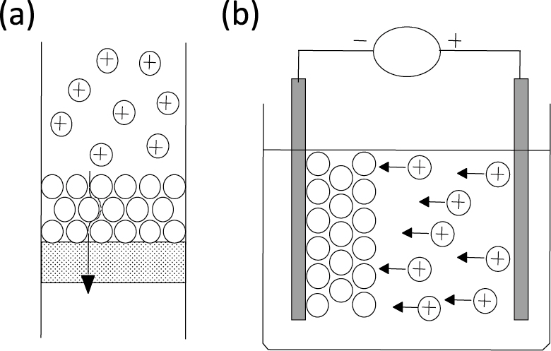
Tape casting is a method for forming a sheet film in which the suspension is poured onto a moving sheet via a knife edge, a so-called doctor blade. This process is widely used to form a laminated layer. In electrophoretic deposition (EPD), charged particles are moved and deposited on a substrate in an externally applied electric field. This method is suitable for the fabrication of ceramics with a highly controlled structure from fine particles because the deposition rate is high, regardless of the particle size, and the position and arrangement of the particles as well as the layer thickness can be controlled via the electric field (Fig. 1(b)) (Sarkar P. and Nicholson P.S., 1996; Besra L. and Liu M., 2007; Sakka Y. and Uchikoshi T., 2010).
As another colloidal processing without accompanying dehydration, gel casting and floc-casting have received increased attention because of isotropic shrinkage and precise dimensional accuracy (Young A.C. et al., 1991; Omatete O.O. et al., 1997; Santacruz I. et al., 2005; Bednarek P. et al., 2010). These methods are based on in-situ solidification by the polymerization of monomers or flocculation upon heating, etc., using a high-solid loading suspension. When using fine particles, such as a high-solid loading suspension cannot be prepared and a special technique is necessary for applying such a process.
The key to colloidal processing is to control the dispersion and the stabilization of fine particles in a solvent. Therefore, understanding of the characteristics of each particle in the solvent is essential. A ceramic particle is charged in a solvent, particularly in an aqueous suspension, owing to the particle surface (or surface adsorbed species) and solvent. During practical processing, systems where the particle dispersion can be controlled by the pH are limited; therefore, the adsorption of a polyelectrolyte with -COOH or -NH3 on the powder surface is usually conducted. In this case, electrosteric stabilization is expected owing to the surface charge of the electrolyte and the adsorption of the polymer (Cesarano J. et al., 1998; Zhu X.W. et al., 2003; Tang F.Q. et al., 2006). In general, fine particles tend to agglomerate and a redispersion treatment in a solvent is necessary.
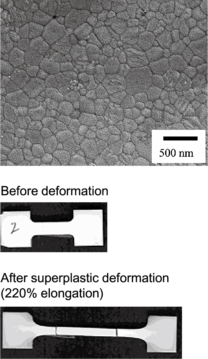
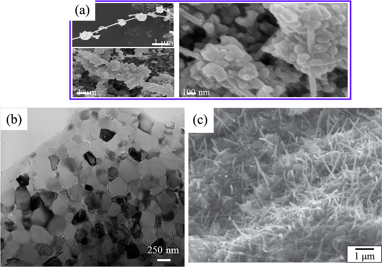
For the redispersion of nanoparticles and heavily aggregated particles, bead milling using small beads with a size of 15–50 μm is effective (Inkyo M. et al., 2006; Suárez G. et al., 2009a,b; Ogi T. et al., 2017). Fig. 2 shows fine particles of hydroxyapatite (HAP) with a mean size of 48 nm, heavily aggregated HAP particles with a mean size of 280 nm after ultrasonic irradiation, and HAP particles with a mean size of 280 nm after milling using zirconia beads with a size of 50 μm. From the figure, it can be seen that the dispersion of the fine particles and heavily agglomerated particles by ultrasonic irradiation is difficult; however, it is possible by bead milling. A dense compact with a narrow distribution of pore size was fabricated by the pressure filtration of a suspension of fine HAP particles. After sintering at 1000 °C, dense and fine grained HAP with a mean grain size of 170 nm was successfully fabricated (Fig. 3).

In ceramic materials in which the grains are rigid, the combination of grain-boundary sliding, grain switching and grain rearrangement due to diffusion (Ashby M.F. and Verrall R.A., 1973; Gifkins R.C., 1978) can be regarded as the main mechanism of superplastic deformation. If this combination is ideally uniform and successive, then superplastic deformation is also uniform and successive without cavitation damage along grain boundaries or at multiple junctions. For such an ideal case, the stress– strain rate relationship is given by
|
ɛ
˙
=
A
σ
0
n
d
p
exp
(
-
Q
R
T
)
| (1) |
Here,
ɛ
˙
indicates the strain rate; A, a constant; σ0, the stress; n, the stress index; d, the grain diameter; p, the grain diameter index; Q, the activation energy; R, the gas constant; and T, the temperature. For a fixed combination of stress and temperature, Eq. (1) implies that the strain rate can be increased by a reduction in the grain size. In actual ceramic materials, however, the combination of grain–boundary sliding, grain switching and grain rearrangement and accommodation is not ideal. Also note that Eq. (1) does not consider any microstructural changes during deformation. Experimental studies have shown that superplastic deformation is inherently accompanied by accelerated grain growth (dynamic grain growth) and intergranular cavitation. The former increases the level of flow stress for a given strain rate and enhances the latter. Since cavitation damage leads to premature failure or degrades the post deformation strength, consideration of these dynamic phenomena is indispensable for attaining superplastic deformation (Hiraga K. et al., 2002, 2005, 2007).
Therefore, the factors contributing to the superplastic deformation in monolithic ceramics are the refinement of the grain size, the decrease in the initial defect density, and a homogeneous microstructure (Sakka Y. et al., 2001; Hiraga K. et al., 2007). These are the merits of colloidal processing using fine particles.
When the strain rate was 5.56 × 10⁻⁵/s at 1100 °C, the tension extension of the fine-grained and dense HAP reached the maximum value of 220%, and the superplasticity (above 200% elongation) was achieved in HAP for the first time. Fig. 3 also shows the shape of the test specimen before and after the tensile test.
3. Heterocoagulation method
Fig. 4 schematically shows the relationship between the pH and zeta potential of components A and B, and the dispersion state of both components. In regions b and d in the figure, the flocculation of one component occurs owing to a low zeta potential, and the dispersion state cannot be established, as schematically shown. In regions a and e, a well-dispersed suspension is obtained owing to the higher zeta potential of both components. In region c, both components are dispersed, but a heterocoagulated suspension is obtained owing to their opposite zeta potentials. In the multicomponent systems, either a well-dispersed suspension or a heterocoagulated suspension is used to obtain a homogeneous microstructure. For a dispersed suspension, segregation during colloidal filtration is a common problem owing to differences in the sedimentation rate, but it can be minimized by using a suspension with a high solid content.
3.1 Ordered porous ceramics
The heterocoagulation method is also applicable to the preparation of porous materials as is schematically shown in Fig. 5 (Tang F. et al., 2003a, b, 2004; Sakka Y. et al., 2005a). This is based on the templating-assisted approach of a core-shell composite, in which monodisperse polymer spheres are used as templates, and ceramic particles act as the target materials. By particle surface modification, well-dispersed suspensions of the polymer and ceramic particles with high opposite charges can be obtained at the same pH. When two suspensions are mixed, an electro-static attractive force is induced between the polymer and ceramic particles, and the polymer particles are uniformly modified by the ceramic particles. After vacuum filtration of the suspension obtained by the heterocoagulation process, the composite is subjected to calcination at a predetermined temperature to remove the spherical polymer particles and loosely sinter the ceramic particles. Through these processes, ordered porous ceramics with regularly arranged pores having the same shape are obtained.
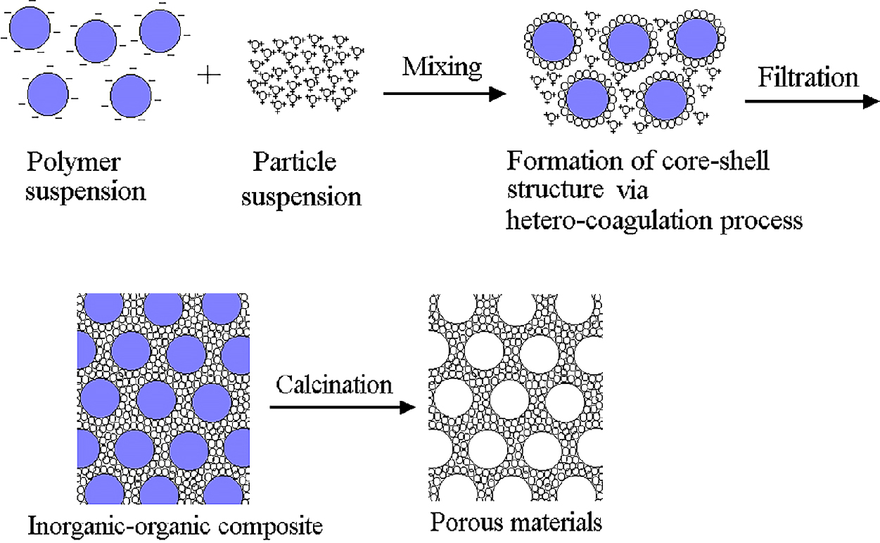
Fig. 6 shows the relationship between the pH and zeta potential of aqueous suspensions when (1) polymethyl-methacrylate (PMMA) particles 1300 nm in size, (2) titania particles 30 nm in size, and (3) titania and polyethyleneimine (PEI) particles, were added (Tang F. et al., 2003a). Appropriate amount of PEI was added as a polyelectrolyte to the suspension containing titania to add positive charges to the titania particles, which are negative at pH = ~8, similarly to PMMA. Well-dispersed suspensions with PMMA and with titania and PEI were prepared at pH = ~8 and mixed to enable heterocoagulation. Fig. 7 shows a scanning electron microscopy (SEM) image of a fractured surface of porous titania obtained by vacuum casting, calcinating for 4 h at 500 °C, and heating again at 850 °C (Tang F. et al., 2003a). It can be seen that three-dimensional porous titania with a uniform pore size was obtained.

Using this method, porous materials of different systems with different particle sizes may be easily fabricated by changing the type and size of the ceramic and polymer particles (Tang F. et al., 2004; Sakka Y. et al., 2005a).
3.2 Highly conductive carbon nanotube (CNT)- dispersed alumina
CNTs with excellent strength and elastic moduli as well as high chemical, thermal and electrical properties (Iijima S. et al., 1996; Falvo M.R. et al., 1997; Palaci I. et al., 2005) have been considered as an ultimate additive to improve the mechanical and electrical properties of conventional ceramics such as alumina. As a method of increasing its conductivity while maintaining its mechanical properties, large amount of multiwall carbon nanotubes (CNTs) is added to alumina. In fact, however, the ability of CNTs to directly improve the macroscopic mechanical properties of CNTs reinforced ceramics has been questioned and debated mainly owing to CNTs agglomeration, poor CNT/matrix interfacial compatibility, CNTs damage during processing (Estili M. and Sakka Y., 2014a). To this end, it is necessary to prepare a mixed powder in which CNTs and alumina are well dispersed and to fabricate a dense sintered material (Estili M. and Sakka Y., 2014a).
High-purity CNT (Bussan Nanotech), synthesized by a catalytic-CVD process and graphitized at about 2600 °C, was prepared and functionalized as follows. The CNT powder was treated with a mixture of H2SO4 and HNO3 with a volume ratio of 3:1 at 110 °C for 20 min. The oxidative agent produced by the sulfonitric mixture was found that oxidation starts with the C-C and C-H bonds generating different oxidized groups from alcohol to carboxylic acid, following a sequential oxidation (Gomez S. et al., 2017). The mixtures were cooled with water and washed up to pH = 7. The hydrophilic CNT powder obtained was dispersed in water by ultrasonic irradiation at pH = 4.4, resulting in the surfactant-free and COOH-terminated CNT aqueous suspension.
Suspensions of the hydrophilically treated CNT powder and alumina powder were separately prepared (Estili M. and Kawasaki A., 2008; Estili M. et al., 2008, 2012, 2013). Considering the different surface potentials of CNTs and alumina under acidic conditions, the suspensions were mixed at pH = 4.4 and subjected to heterocoagulation to obtain a well-dispersed mixed powder (Fig. 8). By SPS of the CNT–alumina mixed powder (Fig. 9, upper) at 1300 °C, a dense nanocomposite of 20 vol% well-dispersed CNT dispersed alumina (Fig. 9, lower) was obtained. This sintered material exhibited an electrical conductivity of 5000 S/m, which is the highest reported for an alumina-based material (Estili M. et al., 2012, 2013). The bending strength and fracture toughness of the obtained sintered material with different amounts of CNTs increased up to a CNTconcentration of 10 vol%. It is seen in Table 2 that the bending strength and fracture toughness obtained with the addition of 20 vol% CNTs were similar to those without the addition of CNTs (Estili M. et al., 2012).
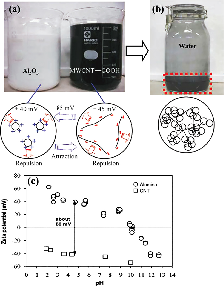
Table 2
Comparison of mechanical properties of alumina and CNT dispersed alumina hybrid.
| SPSed bulks |
Density (g cm−3) |
Strain to failure (%) |
K1C(MPa m0.5) Three-point bending (SENB method) |
Flexural strength (MPa) Four-point bending |
| α-Al2O3 (reference material) |
3.960 (100%) |
0.105 |
4.41 |
395.82 |
| 2.0 vol% hybrid |
3.901 (99.44%) |
0.11 (+8.2%) |
5.78 (+31%) |
413.46 (+4.5%) |
| 10.0 vol% hybrid |
3.733 (98.91%) |
0.19 (+81%) |
6.71 (+52.2%) |
483.19 (+22%) |
| 20.0 vol% hybrid |
3.544 (98.8%) |
0.21 (+98%) |
4.62 (+4.7%) |
403.72 (+2%) |
This method has been attracting interest as a fabrication method for high-strength, high-conductivity oxide and non-oxide ceramics (Estili M. and Sakka Y., 2014a; Wu W.W. et al., 2017). This method is also applicable to the graphene dispersed ceramics (Estili M. et al., 2014b).
4. Control of crystal orientation by colloidal processing in strong magnetic field
The rotation of particles in a magnetic field is caused by the generation of a magnetic torque due to magnetic anisotropy. If the crystal structure is asymmetrical, such as tetragonal or hexagonal, the magnetic susceptibility depends on the direction of the crystal axis and shows anisotropy. On the basis of the interaction between the anisotropy and the magnetic field, the magnetic torque given by Eq. (2) induces the rotation of particles (Suzuki T.S. et al., 2001; Sakka Y. and Suzuki T.S., 2005b).
|
T
=
-
Δ
χ
V
B
2
sin
2
θ
/
2
μ
0
| (2) |
Here, T is the magnetic torque, μ0 is the magnetic the permeability of vacuum, Δχ is the anisotropy of magnetic susceptibility, V is the volume of particles, B is the magnetic flux density, and θ is the angle between the easy axis of magnetization and the direction of the applied magnetic field. The magnetic torque is usually regarded as negligible because the magnetic susceptibilities of para-magnetic and diamagnetic materials are extremely small. However, with recent advances in the technology of superconductivity, strong magnetic fields exceeding 10 T are now more easily obtained without supplying liquid He, enabling orientation using magnetic torque. Our research group has demonstrated that it is possible to control the crystal orientation of alumina, titania, aluminum nitride, silicon carbide, zinc oxide, silicon nitride, HAP, and piezoelectric ceramics, all of which are diamagnetic and have extremely small magnetic susceptibility, by colloid processing in a strong magnetic field (Sakka Y. and Suzuki T.S., 2005b; Suzuki T.S., et al., 2006a). The uniaxial orientation of alumina and titania is possible by the application of a static magnetic field because their magnetic susceptibilities along the c-axis are higher than those along the a, b-axis (Sakka Y. and Suzuki T.S., 2005b; Suzuki T.S. et al., 2006b). In contrast, for aluminum nitride, silicon carbide, zinc oxide, silicon nitride, and HAP, only a c-plane-oriented material is obtained when a static magnetic field is applied because their magnetic susceptibilities along the a, b-axis are higher than those along the c-axis. In this case, uniaxially oriented materials are fabricated using a rotating magnetic field (Tanaka S. et al., 2006; Suzuki T.S., et al., 2009, 2010; Zhu X. and Sakka Y., 2008a; Zhu X. et al., 2010, 2014).
Fig. 10 compares the Lotgering orientation factor (Lotgering F.K., 1959), grain size, and relative density of heavily agglomerated HAP after ultrasonic irradiation (R-HAP) and redispersed HAP after bead milling treatment (B-HAP) after sintering at fixed temperatures. The higher degree of orientation for the B-HAP is mainly due to the deagglomeration by the milling procedure. It is well known that the slip casting of a well-dispersed suspension yields a dense green body with a narrow pore size distribution, which results in a dense and fine-grained micro-structure characterized by low-temperature sintering. This colloidal processing technique is also useful for obtaining highly oriented ceramics.
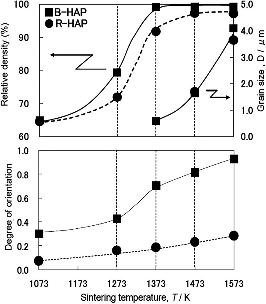
It can be seen that the orientation factor is promoted by sintering at higher temperatures. The magnetic energy is proportional to the volume of the particle, the square of the magnetic field, and the difference between the crystal susceptibility of a, b and that of c. The orientation factor of HAP is basically determined by the particle size and the magnetic field when each particle is well dispersed. However, owing to thermal fluctuation, each particle tends to align in a specific direction with some distribution of the angle. Therefore, the orientation factor is not so large initially. Then the orientation factor increases with grain growth, where the oriented particles act as a template for the oriented grain growth. These features are confirmed by in situ observation (Hirota N. et al., 2008; Terada N. et al., 2008).
To obtain oriented materials with weak magnetic susceptibility, the following conditions are necessary (Sakka Y. and Suzuki T.S., 2005): (1) the particles should be single-crystal and well dispersed, (2) the crystal structure should be noncubic to yield an anisotropic magnetic susceptibility, (3) the magnetic energy should be larger than the thermal motion energy, (4) the viscosity of the suspension should be sufficiently low for the particles to be rotated with a low energy, and (5) grain growth is necessary to obtain a highly oriented structure, particularly when spherical particles are used. For colloidal processing, slip casting, gel-casting, and EPD have been conducted as will be shown later.
5. Ceramics with highly controlled microstructures
5.1 Highly oriented ceramics
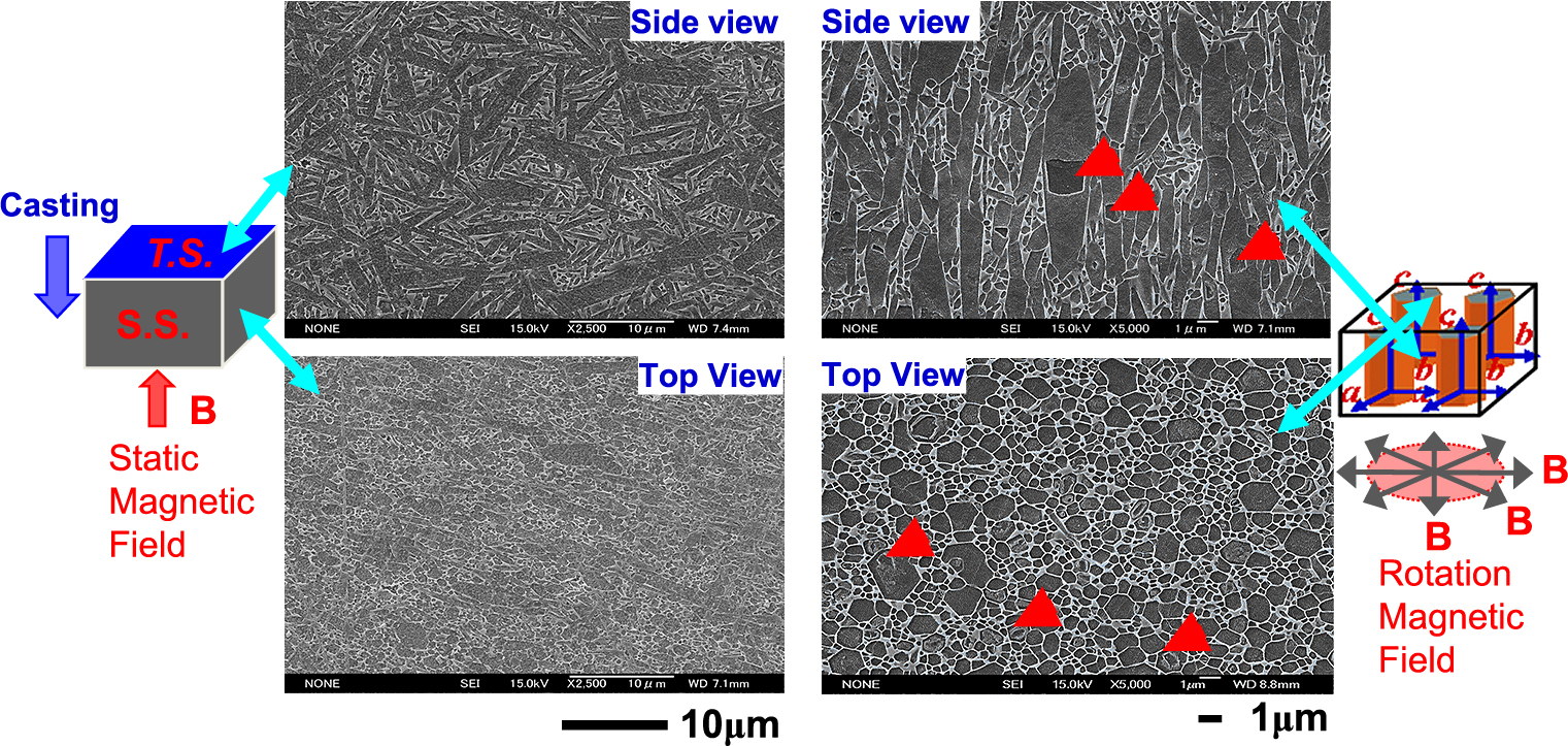
As shown in the previous session, when the magnetic susceptibility along the a, b-axis is higher than that along the c-axis, uniaxially oriented materials can be fabricated using a rotating magnetic field. As an example of the merit of using a rotating magnetic field, the processing of textured β-Si3N4 is discussed (Zhu X.W. et al., 2006, 2008, 2010). α-Si3N4 (Ube Industry’s SN-E10) was used as a raw powder, and 5 mol% Y2O3 and 5 mol% Al2O3 were added as sintering aids. As a seed, 5 mol% β-Si3N4 was added. Ethanol was used as a solvent, 1 wt% PEI was used as a dispersant, and a 30 vol% slurry was prepared. After slip casting under 12 T followed by consolidation, drying, cold isostatic pressing (392 MPa), and calcination (500 °C for 2 h in air), sintering was conducted in a graphite resistance furnace at 1800 °C in 0.2 MPa N2.
As shown in Table 3, a static magnetic field leads to a large decrease in the intensity ratio between the (200) and (101) planes from the top surface to the side surface, indicating the orientation of the a, b-axis (Zhu X.W., et al., 2008b, 2010). On the other hand, the rotating magnetic field allows the intensity between the (002) and (200) planes to become zero on the side surface, indicating the successful orientation of the c-axis. Clearly, the addition of the β-Si3N4 seed leads to the substantially higher orientation of β-Si3N4 crystals in green bodies in both cases, as indicated by the larger intensity ratios on the top surfaces. Fig. 11 schematically shows orientation mechanism of static and rotating magnetic fields. Fig. 12 shows the microstructures of β-Si3N4 slip-cast in a static magnetic field of 12 T (left) and β-Si3N4 consolidated in a rotating magnetic field (right). Elongated β-Si3N4 grains were observed in random directions on an oriented c-plane in a static magnetic field. In contrast, elongated β-Si3N4 grains were oriented uniaxially along the c-axis in a rotating magnetic field.
Table 3
Orientation of β-Si
3N
4 grains in the green and sintered bodies using a static magnetic field (SMF) and rotation magnetic field (RMF).
| Sample |
Tested surface#
|
Texture in green body |
Texture in sintered body |
| XRD Intensity ratio |
Lotgering orientation factor (f*) |
| SMF |
RMF |
SMF |
RMF |
| I(200)/I(101)
|
I(002)/I(200)
|
15 min |
6 h |
1 h |
3 h |
| Non-seeded |
TS (⊥ B) |
2.90 |
≈0.5 |
0.68 |
0.88 |
0.17 |
0.24 |
| SS (//B) |
0.75 |
≈0 |
| Seeded |
TS (//B) |
12.4 |
5.07 |
0.86 |
0.97 |
0.49 |
0.51 |
| SS (⊥ B) |
0.89 |
≈0 |
# TS = top surface, SS = side surface.
*
f = (
P −
P0)/(
1 −
P0), for SMF,
P0 = ∑
I0(hk0)/∑
I0(hkl)
(JCPDS card), P = ∑I(hk0)/∑I(hkl) (sample); for RMF, P0 = ∑I0(00l)/∑I0(hkl), P = ∑I(00l)/∑I(hkl).

Using Y2O3 and MgSiN2 powders as sintering aids, the fabrication of β-Si3N4 with a high thermal conductivity of 176 Wm−1K−1 along the c-axis was successful (Zhu X.W. et al., 2014). When silicon nitride thus obtained is used as a heat-radiating substrate, the c-axis can correspond to the thickness direction. Thus, heat-sink substrates made of β-Si3N4 are expected to be used in power electronics.
To control the structure of high-functionality materials, biaxial or triaxial orientations are desired rather than a uniaxial orientation.
Bi3TiNbO9 planar particles with a biaxial orientation can be obtained by employing gravity and applying a magnetic field (Keskinbora K. et al., 2010; Suzuki T.S. et al., 2013; Gao Z.P. et al., 2015). For platelet particles with micron-order sizes, the largest energy in the dispersion state is the gravitational energy. Therefore, platelet particles are first oriented parallel to the bottom surface, and then they are oriented biaxially by applying a magnetic field. In this case, the lattice constants a and b are similar (Suzuki T.S. et al., 2013). To obtain a triaxially oriented ceramics, platelet Bi4Ti4O15 particles, for which the lattice constants a, b, and c are different in the orthorhombic structure, were used and a two-step procedure involving the application of a magnetic field from two directions sequentially were employed (Suzuki T.S. et al., 2016). In addition, triaxially oriented Y2Ba4Cu7Oy, which is para-magnetic at room temperature, was obtained in an epoxy resin by changing the rate of rotation of a magnetic field at a modulated rate (modulated rotating magnetic field) (Fukushima T. et al., 2008).
5.2 Nacre-like ceramics
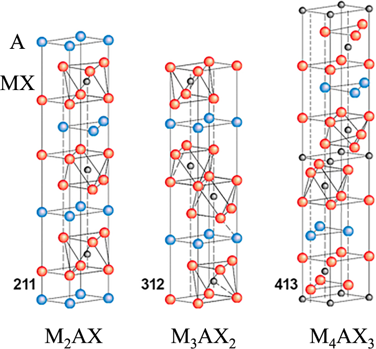
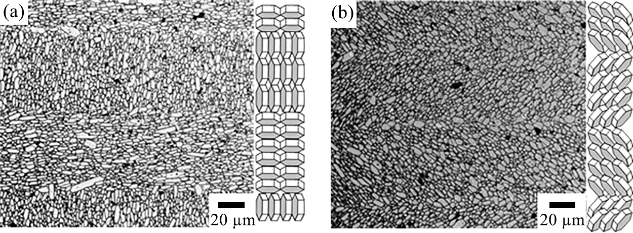
In general, the strength and toughness of ceramics are very difficult to enhance simultaneously; these two factors usually show opposite tendencies. The intrinsic brittleness of ceramics also limits their wide application. The keys to improve material characteristics by controlling the micro-structure can be found in nature (Lin A.Y.M. et al., 2006; Munch E. et al., 2008). Through the process of evolution over millions of years, plants and animals have selected the optimal structures to survive in harsh environments. For example, oriented tabular calcium carbonate layers with a thickness of ~100 nm are laminated in nacre. At the interfaces of the layers, a layer containing several percent of protein membranes is inserted to form an oriented laminated structure (hierarchical structure) in Fig. 13(a) (Lee S.W. et al., 2008; Meyers M.A. et al., 2008). Compared with sintered calcium carbonate, the hierarchical structure has much higher strength and toughness (fracture toughness). To improve both the strength and toughness simultaneously, the microstructure of the material must have (1) weak grain boundary interfaces and (2) rodlike particles and a tabular structure (Lawn B. R. et al., 1994; Tang Z. et al., 2003). Using these requirements as guidelines, Mn+1AXn (MAX; M, transition metal; A, group A element; X, C or N) phase ceramics have attracted attention as nanolaminates, where ideally n = 1–3. MAX has a layered structure (Fig. 14) (Barsoum M.W. and EI-Raghy T., 2001; Wang X.H. and Zhou Y.C., 2010; Sun Z.M., 2011).

As an example, the results of the microstructure and mechanical properties for the MAX phase ceramic Nb4AlC3 are shown (Hu C. et al., 2011a, b, c). The weak bonding between Al atom layers, and Nb and C atom layers contributes to the easy formation of dislocations and their slipping, which induce the development of kink bands in the grains exhibiting “quasi-plastic” behavior. To align Nb4AlC3 nanoparticles on a layer, a suspension of Nb4AlC3 particles is slip cast in a strong magnetic field and subjected to SPS to obtain a dense compact. From SEM and transmission electron microscopy (TEM) images, the obtained structure has a nacre-like microstructure with layer stacking from the nanoscale to the milliscale shown in Fig. 13(b). Undoubtedly, the microstructure design explains the mechanical responses. Single-edge notched bending (SENB) samples tested along the c-axis direction exhibited the zigzag fracture mode. The zigzag fracture surface corresponds to a high surface energy transformed from the mechanical energy. Additionally, the investigation of the microscale zigzag fracture surface revealed pull-out grains distributed on the entire surface, which means that the toughening mechanisms may involve crack deflection, which increases the surface energy, and crack bridging, which lowers the stress intensity factor at the crack tip (Dericioglu A.F. and Kagawa Y., 2002)
Fig. 15 shows a diagram of the flexural strength and fracture toughness of the textured Nb4AlC3 ceramic in comparison with those of other advanced ceramics and other textured MAX phase ceramics (Zhang H.B. et al., 2015). Here the oxide phase is introduced during the powder processing. Textured Nb4AlC3 ceramics have the highest bending strength and fracture toughness. The textured MAX phase ceramics are also expected to show anisotropic properties such as electric and thermal conductivities, oxidation resistance, and tribological properties (Xu L.D. et al., 2017). In addition, the processing of MAX phase ceramics is straightforward (Mishra M. et al., 2012a, b; Zhou T.L. et al., 2014; Sato K. et al., 2014a, b; Idzkowska A. et al., 2015). Therefore, structural components with a complicated shape can be easily formed, which is expected to lead to the development and design of high-performance layered ceramic materials.
5.3 Laminated composites
As shown in session 2, during the EPD in which particles themselves move, the deposition rate does not depend on the particle size and is extremely fast. Based on this point, EPD is a suitable method for consolidating nanoparticles and EPD has received a significant amount of attention for fabricating highly structured controlled ceramics resulting in advanced ceramics. As compared with tape casting, EPD is also suitable for the production of thickness-controlled laminates with good adherence between the layers (Uchikoshi T. et al., 2002). Therefore, recently EPD has recently been applied in many fields.
We have demonstrated that EPD in a high magnetic field is an excellent method to fabricate thick crystalline textured ceramic bodies (Uchikoshi T. et al, 2003, 2004). Fig. 16 shows a schematic of the experimental setup used for EPD in a strong magnetic field. By changing the angle between the magnetic field and the electric field (ϕB–E) during the superposed application of the two fields, the crystal orientation with respect to the substrate is controlled. In addition, by changing ϕB–E during EPD at predetermined intervals, layers with different crystal orientations can be deposited.
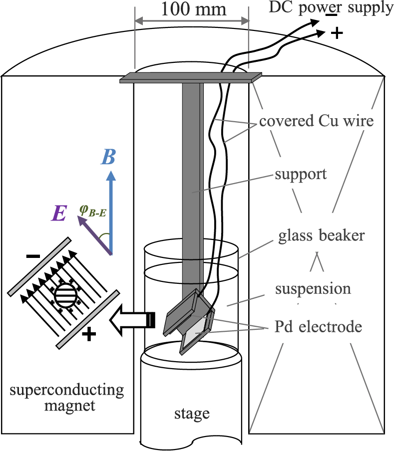
Fig. 17 shows an example of a crystalline textured alumina/alumina laminated composite deposited by alternately applying magnetic fields with (a) ϕB–E = 0° and 90° and (b) ϕB–E = 45° and −45°. It was possible to align the crystal orientations by controlling ϕB–E, regardless of the crystal orientation of the underlying layer, even when the oriented layers were laminated (Uchikoshi T. et al, 2003, 2004; Suzuki T.S. et al., 2006b).
The orientation and laminating technology is effective not only for controlling the mechanical properties but also for improving the functions and reliability of thermoelectric elements, photoelectrodes, ion conductors, piezoelectrics, and dielectrics (Horii S. et al., 2007; Okamoto T. et al., 2006; Kawakita M. et al., 2009; Yamada H. et al., 2013; Zhang C.N. et al., 2014; Miwa Y. et al., 2015; Matsuda M. et al., 2016).
6. Concluding remarks
Colloidal processing has been attracting attention as a consolidation process utilizing the advantages of fine particles. Controlling the dispersion of fine particles will enable the fabrication of dense sintered materials, porous ceramics and CNTs-ceramic nanocomposites. In addition, applying electric and magnetic fields externally during consolidation is expected to enable the advanced control of the microstructure. In this review, examples of the fabrication of nacre-like ceramics with textured MAX phase ceramics and laminated composites were introduced. Various material properties, such as corrosion resistance, wear resistance, thermal conductivity, electric conductivity, piezoelectric properties, and transparency, depend on the crystal orientation. Therefore, the method outlined in this review is applicable to all ceramics except those with cubic crystals. In future studies, the characteristic structures and related properties will be analysed to optimize the material structure, which is expected to lead to the development of advanced functional ceramics.
Acknowledgements
This study was supported by many colleagues and post-doctoral researchers at the National Institute of Materials Science, and students at the University of Tsukuba, Tokyo University of Science, Hosei University, and Shibaura Institute of Technology. In particular, I would like to express my sincere thanks to Dr. T. Suzuki (senior researcher), Dr. T. Uchikoshi (group leader), Dr. F.Q. Tan, Dr. S. Grasso, Dr. C. F. Hu and Dr. K. Sato, Dr. X.W. Zhu, and Dr. M. Estille for the support in studies on magnetic field orientation, the EPD process, ordered porous materials, the SPS process, high-intensity MAX phase ceramics, the advances in silicon nitride, and the fabrication of CNT nanocomposites, respectively.
Author’s Short Biography
Yoshio Sakka

Dr. Yoshio Sakka is a Senior Scientist and an advisor of Graduate Program Office at NIMS, Japan. He received his B.E. in 1978, M.E in 1980, and PhD in 1983 from Kyushu University. After receiving his PhD he joined the National Research Institute for Metals (present NIMS). He is the author or coauthor of 19 books, above 650 original referee’s papers, above 100 review papers, and above 80 patents (including application). By the above establishment, he received many awards, such as Academy member of World Academy of Ceramics (2009), Richard Brook Award from European Ceramic Society (2011),
KONA Award (2014)
.
References
- Akasay I.A., Molecular and colloidal engineering, Ceramics International, 17 (1991) 267–274.
- Ashby M.F., Verrall R.A., Diffusion-accommodated flow and superplasticity, Acta Metallurgica, 21 (1973) 149–163.
- Barsoum M.W., EI-Raghy T., The MAX phases: Unique new carbide and nitride materials, American Scientist, 89 (2001) 334–343.
- Bednarek P., Szafran M., Sakka Y., Mizerski T., Gelcasting of alumina with a new monomer synthesized from glucose, Journal of the European Ceramic Society, 30 (2010) 1795–1801.
- Besra L., Liu M., A review on fundamentals and applications of electrophoretic deposition (EPD), Progress in Materials Science, 52 (2007) 1–61.
- Cesarano J., Akasay I.A., Bleier A., Stability of aqueous α-Al2O3 suspensions with (methacrylic acid) poly-electrolyte, Journal of the American Ceramic Society, 71(1988) 250–255.
- Dericioglu A.F., Kagawa Y., Fail-safe light transmitting SiC fiber-reinforced spinel matrix optomechanical composite, Journal of Materials Science, 37 (2002) 523–530.
- Estili M., Kawasaki A., Sakamoto H., Mekuchi Y., Kuno M., Tsukada T., The homogeneous dispersion of surfactantless, slightly disordered, crystalline, multiwalled carbon nanotubes in α-alumina ceramics for structural reinforcement, Acta Materialia, 56 (2008) 4070–4079.
- Estili M., Kawasaki A., An approach to mass-producing individually alumina-decorated multi-walled carbon nanotubes with optimized and controlled compositions, Scripta Materialia, 58 (2008) 906–909.
- Estili M., Kawasaki A., Sakka Y., Highly concentrated 3D macrostructure of individual carbon nanotubes in a ceramic environment, Advanced Materials, 24 (2012) 4322–4326.
- Estili M., Sakka Y., Kawasaki A., Unprecedented simultaneous enhancement in strain tolerance, toughness and strength of Al2O3 ceramic by multiwall-type failure of a high loading of carbon nanotubes, Nanotechnology, 24 (2013) 155702.
- Estili M., Sakka Y., Recent advances in understanding the reinforcing ability and mechanism of carbon nanotubes in ceramic matrix composites, Science and Technology of Advanced Materials, 15 (2014a) 064902.
- Estili M., Wu W.W., Khazaei M., Sakka Y., Mechanically reliable thermoelectric (TE) nanocomposites by dispersing and embedding TE-nanostructures inside a tetragonal ZrO2 matrix: the concept and experimental demonstration in graphene oxide-3YSZ system, Science and Technology of Advanced Materials, 15 (2014b) 014201.
- Falvo M.R., Clary G.J., Taylor R.M., Chi V., Brooks F.P., Washburn S., Superfine R., Bending and buckling of carbon nanotubes under large strain, Nature, 389 (1997) 582–584.
- Fukushima T., Horii S., Ogino H., Uchikoshi T., Suzuki T.S., Sakka Y., Ishihara A., Shimoyama J.-I., Kishio K., Tri-axial grain orientation of Y2Ba4Cu7Oy achieved by the magneto-science method, Applied Physics Express, 1 (2008) 111701.
- Gao Z., Suzuki T.S., Grasso S., Sakka Y., Reece M.J., Highly anisotropic single crystal-like La2Ti2O7 ceramic produced by combined magnetic field alignment and templated grain growth, Journal of the European Ceramic Society, 35 (2015) 1771–1776.
- Gifkins R.C., Grain rearrangement during superplastic deformation, Journal of Materials Science, 13 (1978) 1926–1936.
- Gómez S., Rendtorff N.M., Aglietti E.F., Sakka Y., Suárez G., Intensity of sulfonitric treatment on multiwall carbon nanotubes, Chemical Physics Letters, 689 (2017) 135–141.
- Grasso S., Sakka Y., Maizza G., Electric current activated/assisted sintering (ECAS): A review of patents 1906–2008, Science and Technology of Advanced Materials, 10 (2009) 53001.
- Hiraga K., Nakano K., Suzuki T.S., Sakka Y., Processing-dependent microstructural factors affecting cavitation damage and tensile ductility in a superplastic alumina dispersed with zirconia, Journal of the American Ceramic Society, 85 (2002) 2763–2770.
- Hiraga K., Kim B.-N., Morita K., Suzuki T.S., Sakka Y., Microstructural design for high-strain-rate superplastic oxide ceramics, Journal of the Ceramic Society of Japan, 113 (2005) 191–197.
- Hiraga K., Kim B.N., Morita K., Yoshida H., Suzuki T.S., Sakka Y., High-strain-rate superplasticity in oxide ceramics, Science and Technology of Advanced Materials, 8 (2007) 578–587.
- Hirota N., Ando T., Shimada T., Wada H., Sakka Y., In situ observation of magnetic orientation process of feeble magnetic materials under high magnetic fields, Science and Technology of Advanced Materials, 9 (2008) 24211.
- Horii S., Kumagai T., Uchikoshi T., Suzuki T.S., Sakka Y., Shimoyama J.-i., Kishio K., Improvement of thermoelectric performance in magnetically c-axis-oriented bismuth-based cobaltites, Scripta Materialia, 57 (2007) 333–336.
- Hu C., Sakka Y., Grasso S., Nishimura T., Guo S., Tanaka H., Shell-like nanolayered Nb4AlC3 ceramic with high strength and toughness, Scripta Materialia, 64 (2011a) 765–768.
- Hu C., Sakka Y., Tanaka H., Nishimura T., Grasso S, Fabrication of textured Nb4AlC3 ceramic by slip casting in a strong magnetic field and spark plasma sintering, Journal of the American Ceramic Society, 94 (2011b) 410–415.
- Hu C., Sakka Y., Nishimura T., Guo S., Grasso S., Tanaka H., Physical and mechanical properties of highly textured polycrystalline Nb4AlC3 ceramic, Science and Technology of Advanced Materials, 12 (2011c) 44603.
- Iijima S., Brabec C., Maiti A., Bernholc J., Structural flexibility of carbon nanotubes, The Journal of Chemical Physics, 104 (1996) 2089–2092.
- Inkyo M., Tahara T., Iwaki T., Iskandar F., Hogan C.J., Okuyama K., Experimental investigation of nanoparticle dispersion by beads milling with centrifugal bead separation, Journal of Colloid and Interface Science, 304 (2006) 535–540.
- Idzkowska A., Sato K., Sakka Y., Szafran M., Deflocculation and stabilization of Ti3SiC2 ceramic powder in gelcasting process, Journal of the Ceramic Society of Japan, 123 (2015) 1010–1017.
- Kawakita M., Uchikoshi T., Kawakita J., Sakka Y., Preparation of crystalline-oriented titania photoelectrodes on ITO glasses from a 2-propanol-2,4-pentanedione solvent by electrophoretic deposition in a strong magnetic field, Journal of the American Ceramic Society, 92 (2009) 984–989.
- Kawakita M., Kawakita J., Uchikoshi T., Sakka Y., Photoanode characteristics of dye-sensitized solar cell containing TiO2 layers with different crystalline orientations, Journal of Materials Research, 24 (2011) 1417–1421.
- Keskinbora K., Suzuki T.S., Ozer I.Z., Sakka Y., Suvaci E., Hybrid processing and anisotropic sintering shrinkage in textured ZnO ceramics, Science and Technology of Advanced Materials, 11 (2010) 065006.
- Lange F.F., Powder processing and technology for increased reliability, Journal of the American Ceramic Society, 72 (1989) 3–15.
- Lawn B.R., Padture N.P., Cait H, Guiberteau F., Making ceramics “ductile”, Science, 263, (1994) 1114–1116.
- Lee S.W., Kim G.H. Choi C.S., Characteristic crystal orientation of folia in oyster shell, Crassostrea gigas, Materials Science and Engineering: C, 28 (2008) 258–263.
- Lin A.Y.M., Meyers M.A., Vecchio K.S., Mechanical properties and structure of Strombus gigas, Tridacna gigas, and Haliotis rufescens sea shells: A comparative study, Materials Science and Engineering: C, 26 (2006) 1380–1389.
- Lotgering F.K., Topotactical reactions with ferrimagnetic oxides having hexagonal crystal structures—I, Journal of Inorganic and Nuclear Chemistry, 9 (1959) 113–123.
- Maizza G., Grasso S., Sakka Y., Noda T., Ohashi O., Relation between microstructure, properties and spark plasma sintering (SPS) parameters of pure ultrafine WC powder, Science and Technology of Advanced Materials, 8 (2007) 644–654.
- Maizza G., Grasso S., Sakka Y., Moving finite-element mesh model for aiding spark plasma sintering in current control mode of pure ultrafine WC powder, Journal of Materials Science, 44 (2009) 1219–1236.
- Matsuda M., Hashimoto M., Matsunaga C., Suzuki T.S., Sakka Y. and Uchikoshi T., Electrophoretic fabrication of a-b plane oriented La2NiO4 cathode onto electrolyte in strong magnetic field for low-temperature operating solid oxide fuel cell, Journal of the European Ceramic Society, 36 (2016) 4077–4082.
- Meyers M.A., Chen P.-Y., Lin A.Y.-M., Seki Y., Biological materials: Structure and mechanical properties, Progress in Materials Science, 53 (2008) 1–206.
- Mishra M., Sakka Y., Szudarska A., Szafran M., Suzuki T.S., Uchikoshi T., Textured Ti3SiC2 by gelcasting in a strong magnetic field, Journal of the Ceramic Society of Japan, 120 (2012a) 544–547.
- Mishra M., Sakka Y., Hu C.F., Suzuki T.S., Uchikoshi T., Besra L., Electrophoretic deposition of Ti3SiC2 and texture development in a strong magnetic field, Journal of the American Ceramic Society, 95 (2012b) 2857–2862.
- Miwa Y., Kawada S., Kimura M., Omiya S., Kubodera N., Ando A., Suzuki T.S., Uchikoshi T., Sakka Y., Processing and enhanced piezoelectric properties of highly oriented compositionally modified Pb(Zr,Ti)O3 ceramics fabricated by magnetic alignment, Applied Physics Express, 8 (2015) 041501.
- Munch E., Launey M.E., Alsem D.H., Saiz E., Tomsia A.P., Ritchie R.O., Tough, Bio-Inspired Hybrid Materials, Science, 322 (2008) 1516–1520.
- Nicholson P.S., Sarkar P., De D., Proc. Composites at Lake Louise’97 (1997) 54–66.
- Ogi T., Zulhijah R., Iwaki T., Okuyama K., Recent progress in nanoparticle dispersion using bead mill, KONA Powder and Particle Journal, 34 (2017) 3–23.
- Okamoto T., Horii S., Uchikoshi T., Suzuki T.S., Sakka Y., Funahashi R., Ando N., Sakurai M., Shimoyama J.-I., Kishio K., Fabrication of multilayered oxide thermoelectric modules by electrophoretic deposition under high magnetic fields, Applied Physics Letters, 89 (2006) 08
1912.
- Omatete O.O., Janney M.A., Nunn S.D., Gelcasting: From laboratory development toward industrial production, Journal of the European Ceramic Society, 17 (1997) 407–413.
- Palaci I., Fedrigo S., Brune H., Klinke C., Chen M., Riedo E., Radial elasticity of multiwalled carbon nanotubes, Physical Review Letters, 94 (2005) 175502.
- Sakka Y., Suzuki T.S., Morita K., Nakano K., Hiraga K., Colloidal processing and superplastic properties of zirconiaand alumina-based nanocomposites, Scripta Materialia, 44 (2001) 2075–2078.
- Sakka Y., Tang F., Fudouzi H., Uchikoshi T., Fabrication of porous ceramics with controlled pore size by colloidal processing, Science and Technology of Advanced Materials, 6 (2005a) 915–920.
- Sakka Y., Suzuki T.S., Textured development of feeble magnetic ceramics by colloidal processing under high magnetic field, Journal of the Ceramic Society of Japan, 113 (2005b) 26–36.
- Sakka Y., Fabrication of highly microstructure controlled ceramics by novel colloidal processing, Journal of the Ceramic Society of Japan, 114 (2006) 371–376.
- Sakka Y., 4.5.7 Fabrication of nanoceramics by colloidal processing, in: Hosokawa M., Nogi K., Naito M., Yokoyama T. (Eds.), Nanoparticle Technology Handbook, Elsevier, Amsterdam, 2007, pp. 246–250.
- Sakka Y., Suzuki T.S., Uchikoshi T., Fabrication and some properties of textured alumina-related compounds by colloidal processing in high-magnetic field and sintering, Journal of the European Ceramic Society, 28 (2008) 935–942.
- Sakka Y. and Uchikoshi T., Forming and microstructure control of ceramics by electrophoretic deposition (EPD), KONA Powder and Particle Journal, 28 (2010) 74–90.
- Santacruz I., Nieto M.I., Moreno R., Alumina bodies with near-to-theoretical density by aqueous gelcasting using concentrated agarose solutions, Ceramics International, 31 (2005) 439–445.
- Sarkar P., Nicholson P.S., Electrophoretic deposition (EPD): Mechanisms, kinetics, and application to ceramics, Journal of the American Ceramic Society, 79 (1996) 1987–2002.
- Sato K., Mishra M., Hirano H., Hu C.F., Sakka Y., Pressureless sintering and reaction mechanisms of Ti3SiC2 ceramics, Journal of the American Ceramic Society, 97 (2014a) 1407–1412.
- Sato K., Mishra M., Hirano H., Suzuki T. S., Sakka Y., Fabrication of textured Ti3SiC2 ceramic by slip casting in a strong magnetic field and pressureless sintering, Journal of the Ceramic Society of Japan, 122 (2014b) 817–821.
- Suárez G., Sakka Y., Suzuki T.S., Uchikoshi T., Aglietti E.F., Effect of bead-milling treatment on the dispersion of tetragonal zirconia nanopowder and improvements of two-step sintering, Journal of the Ceramic Society of Japan, 117 (2009a) 470–474.
- Suárez G., Sakka Y., Suzuki T., Uchikoshi T., Aglietti E.F., Texture development in 3 mol% yttria-stabilized tetragonal zirconia, Materials Research Bulletin, 44 (2009b) 1802–1805.
- Sun Z.M., Progress in research and development on MAX phases: a family of layered ternary compounds, International Materials Reviews, 56 (2011) 143–166.
- Suzuki T.S., Sakka Y., Kitazawa K., Orientation amplification of alumina by colloidal filtration in a strong magnetic field and sintering, Advanced Engineering Materials, 3 (2001) 490–492.
- Suzuki T.S., Kimura M., Shiratsuyu K., Ando A., Sakka Y., Sakabe Y., Highly controlled orientation of CaBi4Ti4O15 using a strong magnetic field, Applied Physics Letters, 89 (2006a) 132902.
- Suzuki T.S., Uchikoshi T., Sakka Y., Control of texture in alumina by colloidal processing in a strong magnetic field, Science and Technology of Advanced Materials, 7 (2006b) 356–364.
- Suzuki T.S., Uchikoshi T., Sakka Y., Effect of sintering additive on crystallographic orientation in AlN prepared by slip casting in a strong magnetic field, Journal of the European Ceramic Society, 29 (2009) 2627–2633.
- Suzuki T.S., Uchikoshi T., Sakka Y., Effect of sintering conditions on microstructure orientation in α-SiC prepared by slip casting in a strong magnetic field, Journal of the European Ceramic Society, 30 (2010) 2813–2817.
- Suzuki T.S., Miwa Y., Kawada S., Kimura M., Uchikoshi T., Sakka Y., Two-dimensional orientation in Bi4Ti3O12 prepared using platelet particles and a magnetic field, Journal of the American Ceramic Society, 96 (2013) 1085–1089.
- Suzuki T.S., Suzuki Y., Uchikoshi T., Sakka Y., Jones J., Tri-axial crystalline orientation of MgTi2O5 achieved using a strong magnetic field and geometric effect, Journal of the American Ceramic Society, 99 (2016) 1852–1854.
- Tanaka S., Makiya A., Kato Z., Uchida N., Kimura T., Uematsu K., Fabrication of c-axis oriented polycrystalline ZnO by using a rotating magnetic field and following sintering, Journal of Materials Research, 21 (2006) 703–707.
- Tang F., Fudouzi H., Zhang J., Sakka Y., Preparation of macroporous titania from nanoparticle building blocks and polymer templates, Scripta Materialia, 49 (2003a) 735–740.
- Tang F., Fudouzi H., Sakka Y., Fabrication of macroporous alumina with tailored porosity, Journal of the American Ceramic Society, 86 (2003b) 2050–2054.
- Tang F., Fudouzi H., Uchikoshi T., Sakka Y., Preparation of porous materials with controlled pore size and porosity, Journal of the European Ceramic Society, 24 (2004) 341–344.
- Tang F., Uchikoshi T., Ozawa K., Sakka Y., Effect of polyethylenimine on the dispersion and electrophoretic deposition of nano-sized titania aqueous suspensions, Journal of the European Ceramic Society, 26 (2006) 1555–1560.
- Tang Z., Kotov N.A., Magonov S., Ozturk B., Nanostructured artificial nacre, Nature Materials, 2 (2003) 413.
- Terada N., Suzuki H.S., Suzuki T.S., Kitazawa H., Sakka Y., Kaneko K., Metoki N., In situ neutron diffraction study of aligning of crystal orientation in diamagnetic ceramics under magnetic fields, Applied Physics Letters, 92 (2008) 112507.
- Uchikoshi T., Hatton B.D., Sakka Y., Nicholson P.S., Electrical conductivity of a 3Y-TZP/alumina laminate composite synthesized by electrophoretic deposition, Journal of the Ceramic Society of Japan, 110 (2002) 959–962.
- Uchikoshi T., Suzuki T.S., Okuyama H., Sakka Y., Electrophoretic deposition of α-alumina particles in a strong magnetic field, Journal of Materials Research, 18 (2003) 254–256.
- Uchikoshi T., Suzuki T.S., Okuyama H., Sakka Y., Nicholson P.S., Electrophoretic deposition of alumina suspension in a strong magnetic field, Journal of the European Ceramic Society, 24 (2004) 225–229.
- Wang X.H., Zhou Y.C., Layered machinable and electrically conductive Ti2AlC and Ti3AlC2 ceramics: a review, Journal of Materials Science & Technology, 26 (2010) 385–416.
- Wu W.W., Estili M., Zhang G.J., Sakka Y., Dispersion and structural evolution of multi-walled carbon nanotubes in ZrB2 matrix, Ceramics International, 43 (2017) 10533–10539.
- Xu L., Zhu D., Grasso S., Suzuki T.S., Kasahara A., Tosa M., Kim B.-N., Sakka Y., Zhu M., Hu C., Effect of texture microstructure on tribological properties of tailored Ti3AlC2 ceramic, Journal of Advanced Ceramics, 6 (2017) 120–128.
- Yamada H., Suzuki T.S., Uchikoshi T., Hozumi M., Saito T., Sakka Y., Ideal design of textured LiCoO2 sintered electrode for Li-ion secondary battery, APL Materials, 1 (2013) 042110.
- Young A.C., Omatete O.O., Janney M. A., Menchioffer P.A., Gelcasting of alumina, Journal of the American Ceramic Society, 74 (1991) 612–618.
- Zhang C., Uchikoshi T., Liu L., Sakka Y., Hirosaki N., Beta-sialon phosphor deposits fabricated by electrophoretic deposition (EPD) process in a magnetic field, Ceramics International, 40 (2014) 8369–8375.
- Zhang H.B., Hu C.F., Sato K., Grasso S., Estili M., Guo S.Q., Morita K., Yoshida H., Nishimura T., Suzuki T.S., Barsoum M.W., Kim B.N., Sakka Y., Tailoring Ti3AlC2 ceramic with high anisotropic physical and mechanical properties, Journal of the European Ceramic Society, 35 (2015) 393–397.
- Zhou T.L. Kim B., Sakka Y., Hu C.F., Huang Q., Microwave sintering of Ti3Si(Al)C2 ceramic, Journal of the American Ceramic Society, 97 (2014) 2731–2735.
- Zhu X.W., Tang F.Q., Suzuki T.S., Sakka Y., Role of the initial degree of ionization of polyethylenimine in the dispersion of silicon carbide nanoparticles, Journal of the American Ceramic Society, 86 (2003) 189–191.
- Zhu X.W., Suzuki T.S., Uchikoshi T., Nishimura T., Sakka Y., Texture development in Si3N4 ceramics by magnetic field alignment during slip casting, Journal of the Ceramic Society of Japan, 114 (2006) 979–987.
- Zhu X., Sakka Y., Textured silicon nitride: Processing and anisotropic properties, Science and Technology of Advanced Materials, 9 (2008a) 33001.
- Zhu X.W., Suzuki T.S., Uchikoshi T., Sakka Y., Texturing of Si3N4 ceramics via strong magnetic field alignment, Key Engineering Materials, 368–372 (2008b) 871–874.
- Zhu X.W., Sakka Y., Suzuki T.S., Uchikoshi T., Kikkawa S., The c-axis texturing of seeded Si3N4 with β-Si3N4 whiskers by slip casting in a rotating magnetic field, Acta Materialia, 58 (2010) 146–161.
- Zhu X.W., Sakka Y., Zhou Y., Hirao K., Itatani K., A strategy for fabricating textured silicon nitride with enhanced thermal conductivity, Journal of the European Ceramic Society, 34 (2014) 2585–2589.


;%0A%09%09%09newWindow.document.open();%0A%09%09%09newWindow.document.write('<img src=%22./Graphics/36_2019007_18.jpg%22>');%0A%09%09%09newWindow.document.close();%0A%09%09)