Abstract
To create advanced materials with minimal energy consumption and environmental impacts, a green and sustainable powder processing technology is essential. The authors have developed this technique based on powder grinding technology. In this paper, the authors will explain the recent progress of the smart powder processing, and its applications. Firstly, particle bonding process, and novel one-pot processing methods to synthesize nanoparticles, to create nanostructured composite granules and to form nano-porous films on substrates in dry phase will be discussed. Their applications on the advanced material fabrications contributing to the sustainable economy will also be explained. Then, the use of grinding technology in wet processing to synthesize nanoparticles and control their morphology will be explained. Smart powder processing can be a foundation to move forward material development technologies and create many more high-quality advanced materials in the future.
1. Introduction
The 2030 Agenda for Sustainable Development (the 2030 Agenda) is a set of international development goals from 2016 to 2030, which was adopted by the United Nations Sustainable Development Summit held in September 2015 building on the success of Millennium Development Goals (MDGs). The 2030 Agenda listed “Sustainable Development Goals (SDGs)” consisting of 17 goals and 169 targets in order to eradicate poverty and realize a sustainable world. The SDGs are universal goals applicable, not only to developing countries but also developed countries.
Powder technology directly contributes to achieve these goals with a wide range of powder processing technology, and the development of advanced materials is one of the key issues to promote the achievements of these goals (Hosokawa et al., 2007; Naito et al., 2010; 2018). Recently, some novel powder processing techniques have been developed to fabricate the advanced materials. Smart powder processing is a green and sustainable powder processing technology, because it creates advanced materials without consuming a large amount of energy.
In this paper, the authors introduce a smart powder processing developed based on powder grinding technology. Grinding process produces fine particles by giving feed materials the mechanical forces strong enough to break them. From a different viewpoint, the process is thought to be a useful method to act an effective force onto the surface of fine particles for their bonding. This function can be applied for many kinds of particle design and structural control without any heat treatment. Fig. 1 shows the smart powder processing so far developed by the authors, which was developed based on the concept of the particle bonding process to make advanced composites (Koishi, 1987; Yokoyama et al., 1987; Naito et al., 1993; 2009; Naito and Abe, 2006; Naito and Kondo, 2016). The particle bonding process developed by the authors has many unique features. For examples, it establishes direct bonding between particles without any heat treatment or binders of any kind in the dry phase through the enhanced particle surface activation induced by mechanical energy and the high intrinsic surface reactivity of nanoparticles to fabricate desired composite particles.
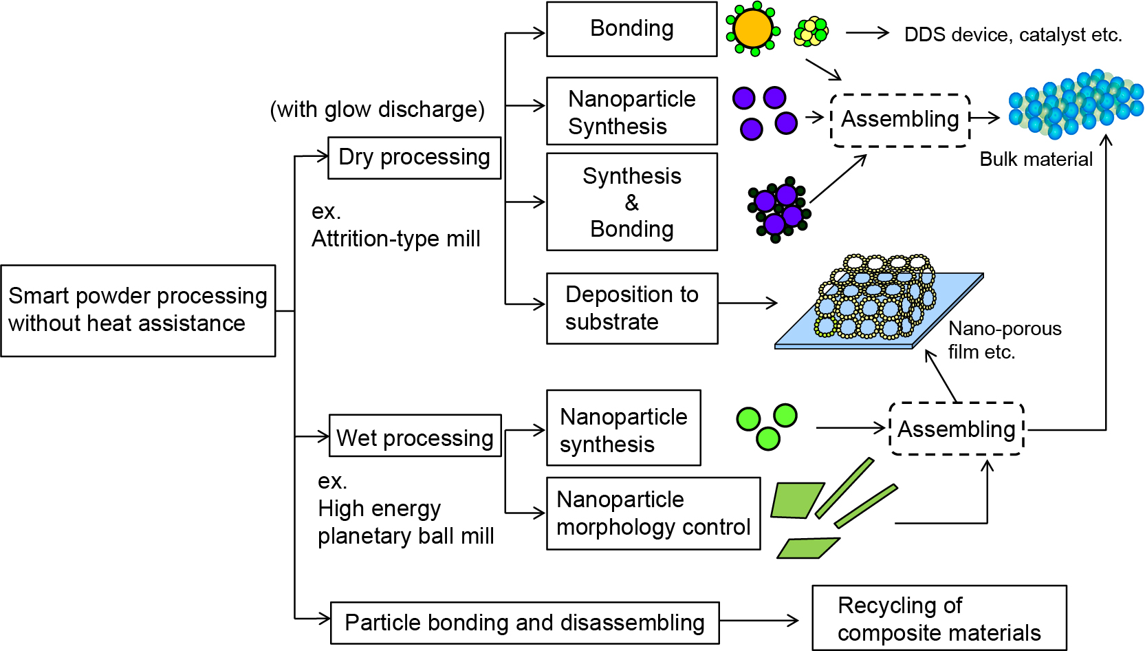
As a result, a new one-pot processing method to synthesize nanoparticles without applying extra heat was achieved using particle bonding technique. Furthermore, both the synthesis of nanoparticles and their bonding with other kind of particles to make nanocomposite granules could be completed at the same time, which leading to the possibility of controlling the nano/microstructure of the composite particles/granules and resulting in customized nano/micro structural new materials by a simple manufacturing process. Besides, as shown in Fig. 1, coating nanoparticles on the substrate to form mechanically deposited nano-porous film was also demonstrated. At the first part of this paper, the dry process of the smart powder processing and its applications for developing advanced materials which contribute to saving energy and providing clean energy are explained (Naito and Kondo, 2016; Naito et al., 2009).
Based on the powder grinding technology, the authors recently developed wet mechanical processing method to synthesize nanoparticles and control their morphology from raw materials in liquid without any heat assistance as shown in Fig. 1. At the second part of this paper, the wet process of the smart powder processing will be explained.
In addition, controlling the bonding between different kinds of materials could also make it possible to disassemble them for the purpose of recycling their elemental components. It led to the development of novel technology for recycling composite materials as demonstrated in the literatures (Naito et al., 2009; 2011; Kondo et al., 2010; 2012).
2. Particle bonding process
Grinding process is to use mechanical forces from the grinding machines to fracture materials into small pieces. From a different viewpoint, the mechanical forces can also be applied on the surface of particles to create inter-particle bonding effects. Table 1 shows the equipment having been applied for making composite particles (Naito et al., 1993). As seen in the Group I, most kinds of fine grinding machines can be used in the particle bonding process. Group II shows the intensive mixing apparatus used for particle bonding applications. Several commercial particle bonding machines have been developed based on their mechanical principles. For example, the MECHANO FUSION® System has a rotating chamber and a fixed arm head with a certain gap against the inside wall of the chamber (Yokoyama et al., 1987; Naito et al., 1993). During its processing, the powder material is pushed next to the inside wall of the rotating chamber by the centrifugal force and is compressed through the gap against the fixed arm head, wherein receiving various kinds of forces, such as compression, shear, attrition, impact and rolling forces. The processed powder is then dispersed by a scraper in the chamber. Particle bonding effect is created as the above actions repetitively applied to the powder material during the chamber rotation. In addition, an electric discharge option is available to generate glow discharge in vacuum between the fixed arm head and the rotating chamber during the operation to activate nanoparticles (Naito and Abe, 2006).
Table 1
Main machines used for particle bonding.
| Type/machines |
| I |
Impaction-type |
| pin mill, disc mill |
| Centrifugal classifying type |
| Attrition-type mill |
| Ball mill |
| tumbling |
| vibration |
| planetary |
| centrifugal fluidizing |
| Agitated ball mill |
| mixing vessel type |
| Jet mill |
| II |
Mortar |
| Cylindrical vessel type with rotating disc |
| Elliptical vessel type |
| with high-speed elliptical rotor |
Prevailing parameters affecting the particle bonding process are summarized in the Fig. 2 (Naito and Kondo, 2016), including the properties of powder materials and the processing conditions.
The properties of powder materials affect the structure and bonding mechanism of composite particles. For making core/shell type composite particles, the particle size ratio between core particles and shell particles should be properly selected. The mixing ratio is also an important factor to form composite particles with a desired structure. For example, the weight fraction of fine particles n is calculated by the following equation (Naito et al., 1993) assuming the fine particles are closely allocated onto the surface of core particle, and dp ≫ da.
|
n
=
(
1
+
3
2
π
×
ρ
p
ρ
a
×
d
p
d
a
)
-
1 | (1) |
where
-
dp : core particle diameter
-
da : fine particle diameter
-
ρp : true density of core particles
-
ρa : true density of fine particles
Eq. (1) is a starting guideline to determine the fine particle fraction. In practice, the fine particle fraction can be selected in a wide range.
As to the bonding mechanism, it depends on the combinations of powder materials and processing conditions. At the contact surfaces between particles, extremely high local temperature and strong mechanical stress were observed (Dachille and Roy, 1960). The local temperature between particles could be ten times higher than the apparent temperature of processing chamber (Nogi et al., 1996). Such a high local temperature could create unique phenomena such as micro-welding or chemical interaction between fine particles and core particles, or among fine particles (Lian et al., 2015).
Apparently, processing conditions such as mechanical actions from the machine rotation can directly affect the performance of particle bonding process. For coating a core particle with fine guest particles, the particle bonding process is proposed as shown in Fig. 3 (Naito et al., 1993). The rotation speed of rotor or chamber and the processing time determine the mechanical actions and its repeated number for processing the powder mixture. This includes two steps: First, the surfaces of fine particles and core particles are mechanically activated, as a result, fine particles adhere onto the surfaces of core particles as the solid line in shown Fig. 3. At this step (Region I in Fig. 3), the BET specific surface area of the composites gradually decreases with processing time. However, at the second step (Region II in Fig. 3), as fine particles deposited on the surfaces of core particles are gradually compacted, BET specific surface area starts leveling off with the processing time, which resulting in lower porosity, smaller pore size, higher mechanical strength of surface layers and stronger bonding between surface layers and core particle. Therefore, the apparent density (porosity and pore size) and strength of surface layers can be controlled by adjusting the rotation speed and its processing time. However, the surface layer formed on the core particle can be fractured after certain processing time if the rotation speed is too high as the dotted line shown in Fig. 3, due to the effect of surface grinding on composite particles (Naito et al., 1993). Besides, Distinct Element Method (DEM) simulation was also applied to a high-speed mixer (Endoh et al., 2004), and to an attrition-type mill (Soda et al., 2012) respectively to elucidate the particle bonding process. Both papers concluded that the motion of core particles, their contact forces and frequencies are important factors to control the particle bonding process.

Temperature and atmosphere during the mechanical processing also affect the performance of particle bonding process. Like the powder grinding operation, particle bonding process generates a large amount of heat. Temperature control is essential when processing heat-sensitive materials. Besides, the processing atmosphere is also important to process powder materials in the dry phase for better products.
To custom the structure of composite particles, the charging procedures of powder materials are critical. Fabricating composite particles with a uniform surface layer of fine particles can be achieved by adding a small amount of fine particles repeatedly into the processed powder at certain time intervals (Naito et al., 1998). As to the multi-layered composite particle, it can be created by adding different kinds of fine powders at certain time intervals. These techniques have been used for many industries including the applications for drug delivery systems (Fukumori et al., 2005).
3. Application of particle bonding process for advanced materials
Particle Bonding Process has a lot of potential to develop various kinds of advanced materials. In this section, the authors introduce the following four kinds of advanced materials which are applied for the purpose of energy saving and clean energy related issues.
3.1 Development of high performance thermal insulation materials
The fabrication of highly performance thermal insulation materials by particle bonding process was reported earlier (Abe et al., 2005; Abe et al., 2008). Interest in thermal insulation materials has been intensified globally, because energy saving issues signified the importance of efficient thermal insulation. In this study, nanoparticle bonding process was used to make composite fibers coated with porous fumed silica layer in the dry phase. Fig. 4 shows the proposed dry processing method to fabricate fumed silica compact by using composite fibers (Abe et al., 2005). Fumed silica / fiber composites porously coated with silica nanoparticles were fabricated at the first stage and then compacted into a board by dry pressing. The composites were produced by a particle bonding process without collapsing the fiber glass and with nano-scale pores made by the fumed silica. The proposed method had the advantage of preventing contacts between fibers in the compacts due to the existence of coating layer.

Table 2 shows the composition of the thermal insulation board (Lian et al., 2015). When the hydrophilic fumed silica nanoparticle is used as starting material, the bonding between hydrophilic glass fiber and nanoparticles in addition to the bonding between nanoparticles is well formed due to the dehydration reaction between OH group on the particle surface. Fig. 5 shows the thermal conductivity of the hydrophilic fumed silica compact specimens (Lian et al., 2015). The light weight board with 86 % porosity (apparent bulk density: 405 kg/m3) was obtained, and its thermal conductivity was 0.031 W/mK at 600 °C. They were lower than molecular conductivity of still air (0.05 W/mK at 400 °C) and at the same level as those obtained from silica aerogel (Kwon et al., 2000) and fumed silica compacts (Smith and Hust, 1989). These results indicated that the obtained compacts had the nano-scale porous structure. The mechanical strength of the compacts depends on their apparent density and the amount of glass fibers as determined by the bending strength. In this case, three-point bending strength was 0.3 MPa. This made it possible to machine the compacts for various applications.
Table 2
Composition of the thermal insulation board.
| Material |
Compounding ratio (mass%) |
Average diameter |
| Fumed silica nano particle (Hydrophilic or hydrophobic) |
60 |
10 nm (Hydrophilic)
12 nm (Hydrophobic) |
| SiC particle |
20 |
3.3 μm |
| Glass fiber |
20 |
10 μm |
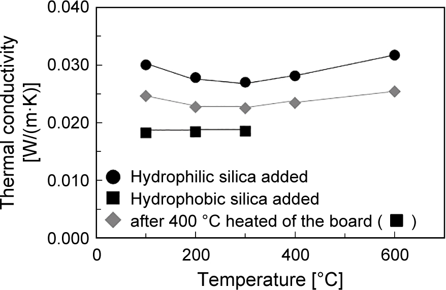
On the other hand, the surface chemical structure of the fumed silica also affects the bonding mechanism between nanoparticles and that between nanoparticles and glass fiber (Lian et al., 2015; 2017). When the hydrophobic fumed silica was used as starting material as shown in Table 2, the thermal conductivity of the obtained specimen showed lower value than that made by hydrophilic fumed silica as shown in Fig. 5. Since the hydrophobic methyl group decomposed around 400 °C, the thermal conductivity of the compact after 400 °C heat treatment was also measured, and found it was increased by the heat treatment, but still lower than that of the compact with hydrophilic fumed silica. Microscopic observation results made clear that the surface layer thickness of hydrophobic fumed silica on the surface of glass fiber was thinner than that of hydrophilic fumed silica due to weaker bond between particles. Therefore, the hydrophobic fumed silica contributed to lower thermal conductivity of the compact. It means that the raw powder properties are also critical to achieve higher performance for the thermal insulation materials. For example, when fumed alumina nanoparticle and ceramic fiber were selected as the starting powder materials, the thermal conductivity of the obtained bulk compact could achieve lower value than 0.065 W/ mK at 1,000 °C. It is a very promising result for thermal insulation materials at very high temperature applications (Tasaka et al., 2020).
3.2 Development of fuel cell electrodes
Fuel cell is touted to be the power generation of 21st century because of their high energy efficiency and clean exhaust. The application of particle bonding process for the fuel cell development has been focusing on making composite particles to reduce its production costs and increase the long-term stability of cells and stacks by lowering its operation temperature without losing power density. For controlling the microstructure of composite electrodes, various kinds of composite particles such as large core-particles coated with nanoparticles (Fukui et al., 2004; Hagiwara et al., 2006; Misono et al., 2006) and inter-dispersed composite mixture consisting of several kinds of nanoparticles (Sato et al., 2009) have been successfully fabricated using the particle bonding process.
For the solid oxide fuel cell (SOFC), nickel-yttria stabilized zirconia (Ni-YSZ) was widely used SOFC anode material due to its excellent electrochemical properties at high temperatures. Fig. 6 shows NiO-YSZ inter-dispersed composite particles consisting of NiO and YSZ nanoparticles processed by particle bonding process (Sato et al., 2009). Fig. 6(a) is the SEM micrograph of the composite particles. Fig. 6(b) is the detailed structure of a composite particle observed by TEM. NiO and YSZ phases in the composite particle were identified by EDX analysis in the micrograph. The micrograph indicates successful fabrication of the composite particles. NiO and YSZ nanoparticles were well dispersed and their sizes were in good agreement with those estimated from the specific surface area of starting particles (NiO: 160 nm and YSZ: 75 nm).

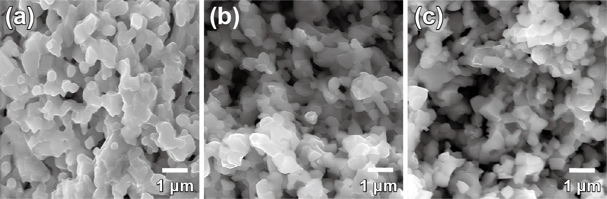
Fig. 7 shows SEM micrographs of the anode made of composite particles before the reduction operation, just after the reduction operation, and after the long-term stability test at 700 °C for 920 h (Sato et al., 2009). Before the reduction operation, the grain size of the anode was smaller than 1 μm without unusually large ones. The NiO shrunk when it was reduced to Ni and producing porous structure in the anode. Thus, the uniform porous structure after reduction as seen in the Fig. 7(b) suggests that Ni was uniformly distributed around the three-dimensional YSZ framework in the entire anode. In addition, there was no significant structural change even after the long-term stability test. The grain size was kept at about 0.5 μm without large grains, which indicating the insignificant grain growth of Ni in the anode made of inter-dispersed composite particles under the testing conditions and exhibiting lower polarization than the anode made of coated composite particles prepared by the authors (Fukui et al., 2004). Controlling the microstructure of composite particles as the starting materials for SOFC anode fabrication is the key to improve its performance.
Particle bonding process is also effective to develop superior electrode of molten carbide fuel cell (MCFC). For example, Ni particles uniformly coated with fine CoO particles were prepared by particle bonding process (Fukui et al., 2000; 2001). A new cathode structure, where the NiO core coated with an outer layer of lithiated cobalt and nickel solid-solution oxide (Li(Co,Ni) oxide), was formed by oxidation and lithiation using the CoO/Ni composite particles. As a result, the solubility of nickel in this Li(Co,Ni) oxide layer into carbonate melt decreased to two-thirds of that of NiO when used as a cathode for MCFCs. Other examples made by the particle bonding process were filament shaped Ni particle uniformly coated by CoO fine particles, and that by MgFe2O4 fine particles as starting material, respectively. The cathode made by the starting composite particles showed lower solubility of nickel into carbonate melt (Fukui et al., 2003).
Furthermore, particle bonding process was applied to develop low-platinum catalyst for polymer electrolyte fuel cell (PEFC) (Munakata et al., 2011). Composite catalyst consisting of tungsten carbide (WC) and platinum/carbon (Pt/C) was fabricated by bonding them together in the dry phase. Small Pt particles with thin carbon layer was observed on the surface of WC particles in the composite catalyst by TEM analysis. The composite catalyst showed a similar catalytic reactivity to that from pristine Pt/C catalyst for hydrogen oxidation with about 25 % of Pt loading (Munakata et al., 2011). It suggests that the particle bonding process is a promising way to develop low cost catalysts for PEFC.
3.3 Development of CNT/Al composites
The advanced carbon nanomaterials with extraordinary mechanical and physical properties, represented by carbon nanotubes (CNTs) and graphene nanosheets, are regarded as ideal reinforcements for developing high performance structural composites. Recently, great efforts have been done to develop carbon nanotubes reinforced aluminum matrix composites, due to the urgent need in many areas such as transportation for advanced light weight structural materials with good stiffness and ductility. For this purpose, a new powder metallurgy route via combination of particle bonding process and shift-speed ball milling process was developed (Chen et al., 2018; 2019). At first, CNTs were well dispersed and uniformly coated on the surface of 6061 Al particles by particle bonding process. Then, the composite particles were processed by a planetary ball mill at low rotation speed for 6 h to make CNT/6061Al flake particles, and processed at high rotation speed for 1 h to make cold welded CNT/6061 Al particles. The obtained composite particles were cold pressed, consolidated by sintering, and hot extruded into rod samples. As a result, the extruded 1.5 mass% CNT/6061Al composites exhibited simultaneous enhancement in Young’s modulus, tensile strength and ductility, compared to the counterpart without particle bonding process at the first step (Chen et al., 2018).
3.4 Development of all-solid-state Li-ion batteries and traditional Li-ion batteries
All-solid-state Li batteries (ASS-LIBs) are suitable applications of 5 V-class cathode materials with high energy densities. However, it was hard to fabricate bulk-type batteries composed of a mixture of active materials and solid electrolytes because of the difficulty of ensuring a conductive path and suppressing the formation of reactive layers at the interface. To solve this problem, the authors proposed the assembling procedures of the composite cathode and the ASS-LIBs as shown in Fig. 8 (Kozawa et al., 2019b). The first step was the mechanical treatment of the composite LiCoPO4 (LCP) granules by particle bonding process. The granule was inter-dispersed composite particle containing the LCP, phosphate-type glass solid electrolyte (AN-15), and multi-walled carbon nanotubes (MWCNT) as the conductive material. They were homogeneously dispersed and organized a network structure as shown in Fig. 8. Then, the produced composite granules were shaped into pellets by pressing. The heat treatment at low temperature brought the AN-15 in close contact with the LCP through softening. The ASS-LIB were assembled by using a Li metal anode and a polymer-solid electrolyte (polymer-SE) film, so that the properties of composite LCP cathodes could be evaluated.

Fig. 9 shows STEM-EELS measurements performed at the interface between LCP and AN-15 solid electrolyte of the cathode pellet. The spectra were collected with a step size of 2 nm. The interface between LCP bulk and SE bulk (AN-15) did not reveal any gaps. The EELS data for the Co-M edge at ~780 eV was collected in the direction from SE bulk to LCP bulk. It revealed no band of the Co-M edge was detected in the region of existence of AN-15. It was concluded that the mechanical and subsequent heat treatment resulted in a good interface between LCP and the AN-15 particles without any Co diffusion. As a result, the first discharge capacity was a bit lower than that of traditional LCP/Li battery using organic liquid electrolytes, but the discharge capacities kept higher value up to 20 cycles. In another case, the inter-dispersed composite granule of LiCoO2/Li1.3Al0.3Ti1.7(PO4)3 was fabricated by the particle bonding process to make the cathode for ASS-LIBs with good results (Nakamura et al., 2016).

Furthermore, the particle bonding process was also applied to improve the anode performance of traditional Li-ion batteries. For example, silicon can be used as anode material due to its high theoretical specific capacity and a relatively low working voltage. However, silicon experiences the large volume changes up to 300 % associated with lithium ion, which leads to poor electrochemical properties caused by loss of the electrical contact between active materials and other effects. To overcome this problem, a new structure of the anode was proposed (Lee et al., 2020). It is the silicon/graphite granular composite with uniform amorphous carbon coating layer. Besides, the granule has uniform inner free space to buffer the volume change of silicon. Actually, the granule was prepared by spray-drying process, and its outer layer was coated with pitch by particle bonding process. Then, the composite granule was heated at 800 °C to form the amorphous carbon coating layer. The pouch cell made by using the composite granule showed good long-term cycle properties with the capacity retention 71 % over 500 cycles at 1 C rate.
4. One-pot mechanical synthesis of nanoparticles without heat assistance
Material synthesis at low temperature using particle bonding process began with the attempt to create MgB2 from raw powders (Abe et al., 2003; 2006). Mechanically processed large magnesium particles and submicron amorphous boron particles could embed boron particles into the surface of magnesium particle. Also, MgB2 was found at this embedded region after being annealed at a low temperature under argon atmospheric pressure.
Particle bonding process with low temperature plasma discharge was also applied to dope TiO2 nanoparticles with nitrogen without providing any heat (Abe et al., 2006), which usually accomplished (Asahi et al., 2001) at 500~600 °C under NH3 flow. Since high temperature could cause undesirable grain-size growth of TiO2 nanoparticles, particle bonding process with low temperature plasma discharge was preferable for this application (Naito and Abe, 2006). NH3 (10 %)/Ar plasma was generated at different gas pressures in a particle bonding processing chamber, where an anatase TiO2 powder with a BET specific surface area of 300 m2/g was processed and uniformly irradiated. As generated plasma irradiation at 300 Pa, the TiO2 powder had a specific surface area of 283 m2/g, and, noticeable absorption in visible light range was observed. In addition, the powder showed an improvement of the photo-catalytic oxidation activity of CH3CHO under visible light. These results indicate that the presented plasma-enhanced particle bonding processing is capable of modifying TiO2 nano-powder to improve its photo-reactivity without much reduction in specific surface area.
Using the features of particle bonding process, new one-pot processing to synthesize nanoparticles without any heat support was developed. First, a rapid synthesis of perovskite type lanthanum manganite starting with a mixture of industrial grade powders was demonstrated (Sato et al., 2006; Ohara et al., 2008a). Traditionally, LaMnO3+δ was synthesized through the solid-state reaction of component oxide powders such as La2O3 and Mn3O4 at 1300 °C, which required many manufacturing steps. Particle size enlargement during the thermal reaction and limited degree of chemical homogeneity with some impurities during the powder processing have been an issue for its producers. However, with the rapid mechano-chemical synthesis, one-pot synthesis of LaMnO3+δ from a mixture of industrial grade La2O3 and Mn3O4 could be accomplished without using any heat. The one-pot processing was applied mechanical forces from the particle bonding process to achieve the solid state reaction on the powder mixture without using ball media.
Adding to the synthesis of LaMnO3+δ, Table 3 summarizes the examples of nanoparticles synthesized by the one-pot mechanical method. It shows various kinds of composite oxides have been synthesized by the one-pot processing. For example, YAG:Ce3+ phosphor is used for white light emitting diodes (LEDs) of next generation lighting. LED is a highly energy-efficient lighting technology, and has the potential to fundamentally change the future of lighting. Widespread use of LED lighting can have greatest impact on energy savings worldwide. However, YAG:Ce3+ phosphor has been manufactured by solid-state reaction at over 1600 °C. To achieve low cost manufacturing of the phosphor with more energy saving process, drastic decrease of the calcination temperature is essential.
Table 3
Examples of synthesized nanoparticles and its applications by the one-pot mechanical method.
| Synthesized nanoparticles |
Applications |
| BaTiO3 (Kondo et al., 2006; Ohara et al., 2008b) |
Dielectric material |
LiCoO2 (Kondo et al., 2014)
LiMnPO4 (Yoshida et al., 2013)
LiFePO4 (Kozawa et al., 2014a; 2015)
LiCoPO4 (Matsuoka et al., 2017)
LiNi0.5Mn1.5O4 (Kozawa et al., 2014b; Kozawa and Naito, 2015) |
Li-ion battery |
La0.8Sr0.2MnO3 (LSM) (Chaichanawong et al., 2006)
La0.6Sr0.4Co0.2Fe0.8O3 (Xi et al., 2015) |
Fuel cell (SOFC) |
| Y2.97Al5O12:Ce3+0.03 (Kanai et al., 2017; 2018) |
Phosphor for LED |
To decrease the synthetic temperature of solid-state reaction, the addition of BaF2 and YF3 was usually used as fluxes. Therefore, the authors achieved the YAG:Ce3+ nanoparticle synthesis by applying the one-pot mechanical synthesis from Y2O3, Al2O3 and CeO2 with BaF2 (Kanai et al., 2017) and those with YF3 (Kanai et al., 2018). This synthesis route is very promising as a novel energy saving process. The only concern was the flux must be removed from the product after the synthesis. Now, further research work to develop one-pot synthesis of YAG:Ce3+ without any flux materials is on-going.
5. One-pot mechanical process to synthesize nanoparticles and their bonding to make nanocomposite granules
The motivation to make nanocomposite granules was raised by the development of the cathode of lithium-ion batteries (LIBs). For example, lithium-ion phosphate (LiFePO4) is one of the key cathode materials for use in large-format LIBs, due to its intrinsic structural and chemical stability that leads to the safety and long cycle life of the batteries. Nevertheless, it has two main obstacles inherent to the practical applications i.e. slow kinetics of lithium-ion diffusion coefficient and poor electronic conductivity. To improve these undesirable properties, the particle size reduction to nano-scale dimensions and the conductive coating on their surfaces become necessary. However, these two approaches lead to another problem i.e. decreasing packing density of electrode, which causes an issue on the energy density of LIBs. One of the breakthrough for this unfavorable problem is to prepare granule particle which has the internal pores to encourage the penetration of electrolyte. As a result, the ideal structure of the starting material of LiFePO4 cathode is designed as shown in Fig. 10 (Kozawa et al., 2014a).
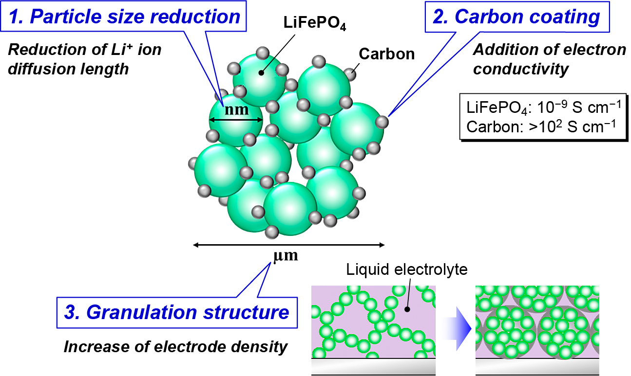
To make the structure, conventional process begins with the synthesis of LiFePO4 by solid-state reaction which needs calcination step controlling the atmosphere by flowing inert or slightly reductive gases to prevent the oxidation from Fe(II) to Fe (III). Then, the surface coating on the synthesized LiFePO4 with a carbon, and the subsequent granulation process is required to prepare the aimed LiFePO4/C composite granule as shown in Fig. 10. However, an ultimate synthesis method for the structure is a direct formation from raw materials under ambient atmosphere.
To achieve this purpose, one-pot mechanical process was applied. Staring materials, Li2CO3, FeC2O4·2H2O and NH4H2PO4 were selected, and ketjen black was used as conductive carbon. The additive of carbon was also helpful to improve the flow abilities of raw powders. The powders were put into the chamber of attrition-type mill and the mechanical synthesis was carried out below 4,500 rpm for 20 min. The processing of attrition-type mill was done under ambient atmosphere.
Fig. 11 shows the XRD patterns of the products (Kozawa et al., 2014a). In spite of the presence or absence of carbon, LiFePO4 was formed by the mechanical treatment under ambient atmosphere. Synthesis of LiFePO4 usually requires inert or reductive gases to prevent the iron oxidation. Therefore, this process has a great advantage over the conventional LiFePO4 synthesis. The effect of carbon addition appeared in the formation of by-product phase. In the case of the mechanical treatment without carbon, impurities were detected as by-products. The oxidation state of iron in Li3Fe2(PO4)3 is trivalent, so that iron oxidation takes place during the mechanical treatment without carbon. On the other hand, by adding the carbon, the formation of trivalent iron compound was suppressed, though trace amount of Li3PO4 was detected. The carbon addition on the mechanical treatment exerted an important role in the prevention of iron oxidation as well as the improvement of conductivity and powder flow ability. Besides, applying higher electric power in the mechanical synthesis, a single phase of LiFePO4 could be obtained in a shorter time.
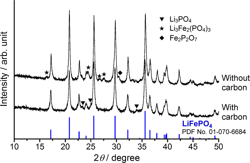
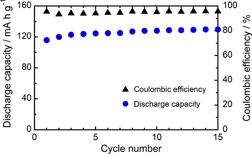
Fig. 12 shows the microstructure of nanoporous LiFePO4/C composite granules prepared by the one-pot mechanical process (Kozawa et al., 2015). As expected from Fig. 10, the granule was composed of synthesized LiFePO4 nanoparticles, and its inside had nanoporous structure as shown on the fracture surface in Fig. 12, Fig. 13 shows the discharge capacity and coulombic efficiency against the cycle number at 0.1 C rate (Kozawa et al., 2015). The discharge capacity gradually increased and reached to 130 mAh/g after 15 cycles. This might be due to the slow penetration of electrolyte into the granules while the coulombic efficiency kept constant at 94–96 % during the cycles. Further design improvement of the granule including the pore structure should be done to advance the performance of the cathode.

The one-pot mechanical process was also applied to prepare nanocomposite granules as the starting materials for the cathode of SOFC (Hosokawa et al., 2014; Xi et al., 2016). In this case, the one-pot mechanical process achieved not only electrocatalyst nanoparticles synthesis from the raw powder materials but also their bonding with solid electrolyte nanoparticles to form inter-dispersed composite granules. The purpose of the composite granule was to create the triple phase boundary (TPB) region as broad as possible while maintaining sufficient porous channels for gas diffusion in the resultant cathode. Actually, the authors prepared the following two kinds of composite granules for this purpose. The first one was the combination of strontium doped lanthanum manganite (LSM) as electrocatalyst and scandium stabilized zirconia (ScSZ) as solid electrolyte (Hosokawa et al., 2014). The second one was the combination of La0.6Sr0.4Co0.2Fe0.8O3(LSCF) as electrocatalyst and Ce0.9Gd0.1O1.95(GDC) as solid electrolyte (Xi et al., 2016).
In the latter case, commercially available La2O3, Sr(OH)2, Co3O4 and Fe2O3 with stoichiometric quantities were put into the chamber with one-fifth of the total amount of GDC nanoparticles, and then, the powders were mechanically treated under ambient atmosphere without external heating. During the mechanical processing, one-fifth of the total amount of GDC powder was added every 4 min. The total processing time was 20 min. The XRD pattern of the composite particles after 20 min. processing exhibited mainly LSCF and GDC phase, and they formed inter-dispersed nanocomposite granules wherein both elements were uniformly dispersed. The obtained cathode after sintering exhibited a finely composed porous structure consisting of fine grains ranging from nano to submicron sizes. It indicated that quite low polarization resistance in the intermediate temperature range. The obtained results suggest that the one-pot mechanical process is a very promising, simple, and energy-saving approach for producing high-quality LSCF-GDC composite powders.
6. Mechanically assisted deposition of nanocomposite film by one-pot processing
To make porous composite films with a large surface area for chemical sensing and energy storage/conversion, direct deposition of mechanically activated nanocomposite particles on the substrates in the dry phase is desirable.
Primarily, the apparatus used in this study (Abe et al., 2012) consisted of a closed vessel and a feather-type rotor. As an example, the anode of Nickel-yttria stabilized zirconia (Ni-YSZ) cermet was fabricated on YSZ substrate by this apparatus. NiO/YSZ composite particles were first put into the chamber and dispersed by the rotor. The dispersed and mechanically activated particles were then transported to the substrate and deposited on it. As reported by Akedo (Akedo, 2006), dense ceramic layer consisting of fractured particles or deformed particles could be successfully formed on the substrate when the ceramic particles speeded up to 100–500 m/s. On the contrary, it was demonstrated that the fine aggregates or clusters could be bonded together at a much lower impact speed of about 30 m/s for making the porous films. Besides, the rapid film formation was found with the nanoparticles due to their high specific surface area.
Fig. 14 shows the effect of the processing time on the thickness of the deposited film with the NiO-YSZ nanoparticles (120 m2/g) (Abe et al., 2012). Noticeable film formation was found at ~ 10 min after starting the process, which indicating that the fine aggregates of the nanocomposite particles were formed and activated in the early stage of the processing and started to deposit on the substrate at an impact speed of about 30 m/s. No unusually large grain was found on the porous film after the heat treatment at 1200 °C. The fine composite microstructure was a result of the homogeneously distributed NiO and YSZ nanograins in the deposited film. The polarization of the porous film as the anode of SOFC showed good performance as reported by Abe etc. (Abe et al., 2012).

The deposition process can be also applied to suppress the mold growth on the surface of materials (Nomura et al., 2018). Mold growth can trigger a variety of serious human health problem such as allergies and asthma. Designing surface unfavorable for the adhesion of fungal spores was considered an effective method to prevent fungal growth. In this study, the effect of hydrophilic surface treatment on the adhesion of fungal spores onto substrates was investigated using Aspergillus oryzae as a model fungus. The glass substrate coated with hydrophilic fumed silica (BET equivalent diameter: 7 nm) was prepared using this method. As a result, the fungal spores that strongly adhered on the coated glass substrate under atmosphere conditions were easily removed by lightly hand-washing in water. In addition, the removal ratio of the fungal spores on the coated glass was higher than that on plasma-treated glass. Atomic force microscopy revealed that there was almost no adhesive force between the spores and the glass substrate coated with fumed silica.
7. Wet mechanical processing to synthesis nanoparticles and their morphology control
Wet mechanical processing has been used to synthesize particles for years. For example, particle synthesis via solid-solution reaction incorporating mechanical actions by using a multi-ring media mill was pioneered by Riman’s group (Shuk et al., 2001; Suchanek et al., 2002). However, variations of particle synthesized by conventional wet mechanical approach are still limited, and the particle preparation with specific morphologies has not been accomplished yet.
The authors applied grinding apparatus used for the particle bonding to synthesize nanoparticles with a unique structure in the wet phase. At first, the synthesis of unique morphology of lithium titanate hydrate, Li1.81H0.19Ti2O5·xH2O (LHTO) was done by applying a high energy planetary ball mill (Suzuki et al., 2017). This material is used as a precursor of Li4Ti5O12 (LTO), a typical LIB anode material. The traditional hydrothermal methods to synthesize LHTO were constrained by the restrictive preparation requirements, such as handling moisture-sensitive titanium precursors and high concentration NaOH solutions. In contrast, the high energy planetary ball mill enabled us to achieve the synthesis and morphology control of LHTO only by using low-cost materials (LiOH and TiO2) at room temperature.
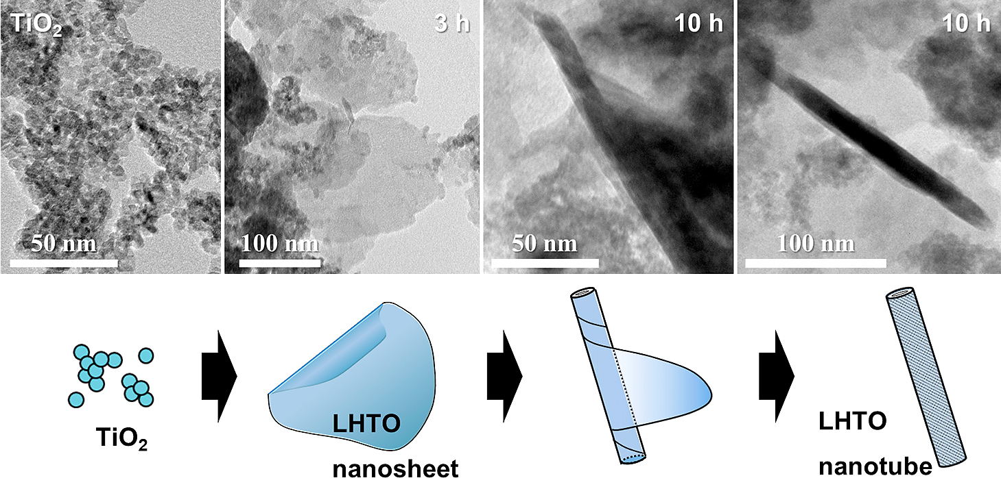
Fig. 15 shows the TEM images of the raw TiO2 powder and the products after planetary ball milling at 150 G up to 10 h (Suzuki et al., 2017). The TiO2 powder used consisted of ultrafine nanoparticles of approximately 5 nm in diameter. After the planetary ball milling, thin sheets of LHTO were formed, and the widespread LHTO sheets were formed after 3 h as shown in the figure. Then, the LHTO sheet was transformed into the nanotube morphology by curling after 5 h and 10 h. Direct formation of LHTO nanotubes was successfully achieved by the wet mechanical method. Then, thermal treatment of the LHTO nanotubes was conducted at 500 °C. As a result, an LTO phase with a spinel structure was obtained, and the nanotube morphology of LHTO was retained in the LTO product. The anode properties of the prepared LTO nanotubes exhibited a first discharge capacity of 160 mAh/g at 0.1 C rate.
To clarify whether the normal or tangential component of collisions makes a larger contribution on the synthesis of LHTO, the effect of collision direction on a reaction rate of LHTO was studied through the combined analysis of the experimental results and the simulated ball motion by Distinct Element Method (DEM) (Kozawa et al., 2021b). As a result, collisions of balls in the normal direction were found to contribute strongly to the wet mechanochemical reaction.
The wet mechanical processing was also applied for the morphology-controlled NH4MnPO4·H2O (Kozawa et al., 2019a) and NH4CoPO4·H2O (ACP) (Kozawa et al., 2021a), respectively. For the latter case, ACP platelets were synthesized via the wet mechanical processing of NH4H2PO4 and Co(OH)2 in water using a planetary ball mill. The formation of ACP was achieved by the dissolution-precipitation reaction, involving the gradual dissolution of water-insoluble Co(OH)2 into the NH4H2PO4-dissolved acidic solution. The use of Co(OH)2 with a brucite-type structure allowed the ready formation of the layered ACP phase. Despite the ball milling treatment, ACP particles with platelet morphologies were produced, and their sizes and shapes were varied, depending on the milling conditions. The formed ACP platelets were subjected to grinding, consequently affording a decrease in size and subsequent dissolution. However, an increase in supersaturation led to the recrystallization and crystal growth of the ACP platelets. This dissolution-recrystallization cycle during milling allows the repeated growth of the ACP platelets. The ACP powder was converted into LiCoPO4, while maintaining the shape and size, by a simple solid-state reaction with Li2CO3. The flake-like LCP cathode exhibited a charge/ discharge plateau at ~4.8 V and a better discharge capacity of 109 mAh/g because of the high specific surface area and small platelet thickness (Kozawa et al., 2021a). Other applications of the wet mechanical processing including the synthesis of Sr3Al2(OH)12 hydrogarnet (Kozawa et al., 2018), and the fabrication of composite cathode of LiMn2O4 coated by LiMnPO4 (Kozawa et al., 2020) have been investigated.
8. Conclusions
Smart powder processing was developed based on powder grinding technology. It is a very promising technique for achieving green and sustainable manufacturing, as well as developing advanced materials contributing to establishing sustainable economy. In this paper, the authors explained the recent progress of the smart powder processing, and its applications. At first, the authors introduced particle bonding process, novel one-pot process to synthesize nanoparticles, process to create nanostructured composite granules, and process to form nano-porous films on substrates in the dry phase. Then, the authors discussed the wet smart processing with grinding technology. Smart powder processing can be a foundation to move forward material development technologies and create many more high-quality advanced materials in the future.
References
- Abe I., Sato K., Abe H., Naito M., Formation of porous fumed silica coating on the surface of glass fibers by a dry mechanical processing technique, Advanced Powder Technology, 19 (2008) 311–320. DOI:10.1163/156855208X314976
- Abe H., Abe I., Sato K., Naito M., Dry powder processing of fibrous fumed silica compacts for thermal insulation, Journal of the American Ceramic Society, 88 (2005) 1359–1361. DOI:10.1111/j.1551-2916.2005.00317.x
- Abe H., Kimitani T., Naito M., Influence of NH3/Ar plasma irradiation on physical and photocatalytic properties of TiO2 nanopowder, Journal of Photochemistry and Photobiology A: Chemistry, 183 (2006) 171–175. DOI:10.1016/j.jphotochem.2006.03.013
- Abe H., Naito M., Nogi K., Kondo A., Fukui T., Ohara S., Matsuda M., Miyake M., Formation of MgB2 superconducting phase from Mg and B composite particles produced by mechanical mixing, in: Characterization & Control of Interfaces for High Quality Advanced Materials: Ceramic Transactions (eds K. Ewsuk, K. Nogi, M. Reiterer, A. Tomsia, S. J. Glass, R. Waesche, K. Uematsu and M. Naito), 146 (2006) 277–282. DOI:10.1002/9781118406038.ch34
- Abe H., Naito M., Nogi K., Matsuda M., Miyake M., Ohara S., Kondo A., Fukui T., Low temperature formation of superconducting MgB2 phase from elements by mechanical milling, Physica C, 391 (2003) 211–216. DOI:10.1016/S0921-4534(03)00932-8
- Abe H., Naito M., Sato K., Mechanically assisted deposition of nickel oxide–yttria stabilized zirconia nanocomposite film and its microstructural evolution for solid oxide fuel cells anode application, International Journal of Applied Ceramic Technology, 9 (2012) 928–935. DOI:10.1111/j.1744-7402.2012.02780.x
- Asahi R., Morikawa T., Ohwaki T., Aoki K., Taga Y., Visible-light photocatalysis in nitrogen-doped titanium oxides, Science, 293 (2001) 269–271. DOI:10.1126/science.1061051
- Akedo J., Aerosol deposition of ceramic thick film at room temperature densification mechanism of ceramic layers, Journal of the American Ceramic Society, 89 (2006) 1834–1839. DOI:10.1111/j.1551-2916.2006.01030.x
- Chaichanawong J., Sato K., Abe H., Murata K., Fukui T., Charinpanitkul T., Tanthapanichakoon W., Naito M., Formation of strontium-doped lanthanum manganite (La0.8Sr0.2MnO3) by mechanical milling without media balls, Advanced Powder Technology, 17 (2006) 613–622. DOI:10.1163/156855206778917751
- Chen M., Fan G., Tan Z., Xiong D., Guo Q., Su Y., Zhang J., Li Z., Naito M., Di Z., Design of an efficient flake powder metallurgy route to fabricate CNT/6061Al composites, Materials and Design, 142 (2018) 288–296. DOI:10.1016/j.matdes.2018.01.044
- Chen M., Fan G., Tan Z., Yuan C., Xiong D., Guo Q., Su Y., Naito M., Li Z., Tailoring and characterization of carbon nanotube dispersity in CNT/6061Al composites, Materials Science &. Engineering. A, 757 (2019) 172–181. DOI:10.1016/j.msea.2019.04.093
- Dachille F., Roy R., High-pressure phase transformations in laboratory mechanical mixers and mortars, Nature, 186 (1960) 34. DOI:10.1038/186034a0
- Endoh S., Szepvologyi J., Hotta T., Naito M., Izumi K., Experimental and theoretical analysis of mechanical coating process of particles with the theta composer, Chemical Engineering Communications, 191 (2004) 1259–1270. DOI:10.1080/00986440490464174
- Fukui T., Murata K., Ohara S., Abe H., Naito M., Nogi K., Morphology control of Ni-YSZ cermet anode for lower temperature operation of SOFC, Journal of Power Sources, 125 (2004) 17–21. DOI:10.1016/S0378-7753(03)00817-6
- Fukui T., Ohara S., Okawa H., Hotta T., Naito M. Properties of NiO cathode coated with lithiated Co and Ni solid solution oxide for MCFCs, Journal of Power Sources, 86 (2000) 340–346. DOI:10.1016/S0378-7753(99)00416-4
- Fukui T., Ohara S., Okawa H., Naito M., Nogi K., Synthesis of metal and ceramic composite particles for fuel cell electrodes, Journal of the European Ceramic Society, 23 (2003) 2835–2840. DOI:10.1016/S0955-2219(03)00296-6
- Fukui T., Okawa H., Hotta T., Naito M., Yokoyama T., Synthesis of CoO/Ni composite powders for molten carbonate fuel cells, Journal of the American Ceramic Society, 84 (2001) 233–235. DOI:10.1111/j.1151-2916.2001.tb00639.x
- Fukumori Y., Ichikawa H., Uemura T., Sato K., Abe H. Naito M., Process performance of dry powder coating for preparing controlled release microcapsules by a high speed mixer, Proceedings of 8th International Symposium on Agglomeration, Bangkok, Thailand, March 16–18 (2005) 31–38.
- Hagiwara A., Hobara N., Takizawa K., Sato K., Abe H., Naito M., Preparation and evaluation of mechanochemically fabricated LSM/ScSZ composite materials for SOFC cathodes, Solid State Ionics, 177 (2006) 2967–2977. DOI:10.1016/j.ssi.2006.08.021
- Hosokawa K., Kondo A., Okumiya M., Abe H., Naito M., One-step mechanical processing to prepare LSM/ScSZ composite particles for SOFC cathode, Advanced Powder Technology, 25 (2014) 1430–1434. DOI:10.1016/j.apt.2013.12.006
- Hosokawa M., Nogi K., Naito M., Yokoyama T., Nanoparticle Technology Handbook, 1st Ed., Elsevier, 2007, ISBN: 9780080558028.
- Kanai K., Fukui Y., Kozawa T., Kondo A., Naito M., Effect of BaF2 powder addition on the synthesis of YAG phosphor by mechanical method, Advanced Powder Technology, 28 (2017) 50–54. DOI:10.1016/j.apt.2016.07.017
- Kanai K., Fukui Y., Kozawa T., Kondo A., Naito M., Effect of flux powder addition on the synthesis of YAG phosphor by mechanical method, Advanced Powder Technology, 29 (2018) 457–461. DOI:10.1016/j.apt.2017.11.002
- Koishi M., Biryushi Sekkei, Kogyo Chousakai, 1987, ISBN:978-4769340508
- Kondo A., Abe H., Isu N., Miura M., Mori A., Ohmura T., Naito M., Development of light weight materials with low thermal conductivity by making use of waste FRP, Journal of the Society of Powder Technology, Japan, 47 (2010) 768–772. DOI:10.4164/sptj.47.768
- Kondo A., Nakamura E., Kozawa T., Abe H., Naito M., Yoshida J., Nakanishi S., Iba H., One-pot mechanical synthesis of the nanocomposite granule of LiCoO2 nanoparticles, Advanced Powder Technology, 25 (2014) 1280–1284. DOI:10.1016/j.apt.2014.03.005
- Kondo A., Ohmura T., Abe H., Kano J., Naito M., Development of recycling process for waste FRP mortar pipe, Journal of the Society of Powder Technology, Japan, 49 (2012) 827–831. DOI:10.4164/sptj.49.827
- Kondo A., Sato K., Abe H., Naito M., Shimoda H., Mechanochemical synthesis of barium titanate from nanocrystalline BaCO3 and TiO2, in: Characterization and Control of Interfaces for High Quality Advanced Materials II: Ceramic Transactions (eds K. Ewsuk, K. Nogi, R. Waesche, Y. Umakoshi, T. Hinklin, K. Uematsu, T. Tomsia, H. Abe, H. Kamiya and M. Naito), 198 (2006) 375–380. DOI:10.1002/9781118144145.ch57
- Kozawa T., Fukuyama K., Kondo A., Naito M., Wet mechanical route to synthesize morphology-controlled NH4MnPO4·H2O and its conversion reaction into LiMnPO4, ACS Omega, 4 (2019a)5690–5695. DOI:10.1021/acsomega.9b00026
- Kozawa T., Fukuyama K., Kondo A., Naito M., Wet milling synthesis of NH4CoPO4·H2O platelets: formation reaction, growth mechanism, and conversion into high-voltage LiCoPO4 cathode for Li-ion batteries, Materials Research Bulletin, 135 (2021a) 111149. DOI:10.1016/j.materresbull.2020.111149
- Kozawa T., Fukuyama K., Kushimoto K., Ishihara S., Kano J., Kondo A., Naito M., Effect of ball collision direction on a wet mechanochemical reaction, Scientific Reports, 11 (2021b) 210. DOI:10.1038/s41598-020-80342-w
- Kozawa T., Harata T., Naito M., Fabrication of an LiMn2O4@ LiMnPO4 cathode for improved cycling performance at high temperatures, Journal of Asian Ceramic Societies, 8 (2020) 309–317. DOI:10.1080/21870764.2020.1743413
- Kozawa T., Kataoka N., Kondo A., Nakamura E., Abe H., Naito M., One-step mechanical synthesis of LiFePO4/C composite granule under ambient atmosphere, Ceramics International, 40 (2014a) 16127–16131. DOI: 10.1016/j.ceramint.2014.07.043
- Kozawa T., Kataoka N., Kondo A., Nakamura E., Abe H., Naito M., Facile preparation of porous LiFePO4/C composite granules by mechanical process, Materials Chemistry and Physics, 155 (2015) 246–251. DOI:10.1016/j.matchemphys.2015.02.038
- Kozawa T., Kondo A., Fukuyama K., Naito M., Koga H., Shimo Y., Saito T., Iba H., Inda Y., Oono T., Katoh T., Nakajima K., Bulk-type all-solid-state batteries with mechanically prepared LiCoPO4 composite cathodes, Journal of Solid State Electrochemistry, 23 (2019b)1297–1302. DOI:10.1007/s10008-019-04218-4
- Kozawa T., Kondo A., Nakamura E., Abe H., Naito M., Koga H., Nakanishi S., Iba H., Rapid synthesis of LiNi0.5Mn1.5O4 by mechanical process and post-annealing, Materials Letters, 132 (2014b)218–220. DOI:10.1016/j.matlet.2014.06.097
- Kozawa T., Naito M., Facile preparation of core@shell and concentration-gradient spinel particles for Li-ion battery cathode materials, Science and Technology of Advanced Materials, 16 (2015) 015006. DOI:10.1088/1468-6996/16/1/015006
- Kozawa T., Suzuki Y., Naito M., Scalable synthesis of Sr3Al2(OH)12 hydrogarnet by wet milling and its thermal decomposition behavior, Materials Chemistry and Physics, 212 (2018) 245–251. DOI:10.1016/j.matchemphys.2018.03.060
- Kwon Y.G., Choi S.Y., Kang E.S., Baek S.S., Ambient-dried silica aerogel doped with TiO2 powder for thermal insulation, Journal of Materials Science, 35 (2000) 6075–6079. DOI:10.1023/A:1026775632209
- Lee D., Kondo A., Lee S., Myeong S., Sun S., Hwang I., Song T., Naito M., Paik U., Controlled swelling behavior and stable cycling of silicon/graphite granular composite for high energy density in lithium ion batteries, Journal of Power Sources, 457 (2020) 228021. DOI:10.1016/j.jpowsour.2020.228021
- Lian T.W., Kondo A., Kozawa T., Akoshima M., Abe H., Ohmura T., Tuan W.H., Naito M., Effect of hydrophobic nano-silica on the thermal insulation of fibrous silica compacts, Journal of Asian Ceramic Societies, 5 (2017) 118–122. DOI:10.1016/j.jascer.2017.03.003
- Lian T.W., Kondo A., Kozawa T., Ohmura T., Tuan W.H., Naito M., Effect of fumed silica properties on the thermal insulation performance of fibrous compact, Ceramics International, 41 (2015) 9966–9971. DOI:10.1016/j.ceramint.2015.04.076
- Matsuoka M., Kondo A., Kozawa T., Naito M., Koga H., Saito T., Iba H., Effect of carbon addition on one-step mechanical synthesis of LiCoPO4/C composite granules and their powder characteristics, Ceramics International, 43 (2017) 938–943. DOI:10.1016/j.ceramint.2016.10.022
- Misono T., Murata K., Fukui T., Chaichanawong J., Sato K., Abe H., Naito M., Ni-SDC cermet anode fabricated from NiO-SDC composite powder for intermediate temperature SOFC, Journal of Power Sources, 157 (2006) 754–757. DOI:10.1016/j.jpowsour.2006.01.074
- Munakata H., Tashita T., Kanamura K., Kondo A., Naito M., Development of low-platinum catalyst for fuel cells by mechano-chemical method, Journal of the Society of Powder Technology, Japan, 48 (2011) 364–369. DOI:10.4164/sptj.48.364
- Naito M., Abe H., Particle bonding technology for composite materials -microstructure control and its characterization, in: Characterization and Modeling to Control Sintered Ceramic Microstructures and Properties: Ceramic Transactions, DiAntonio C. (Ed.), 157 (2006) 69–76. DOI:10.1002/9781118407080.ch8
- Naito M., Abe H., Kondo A., Smart powder processing for energy and environment, WIT Transactions on Ecology and the Environment, 154 (2011) 51–59. DOI:10.2495/CHEM110061
- Naito M., Abe H., Kondo A., Yokoyama T., Huang C.C., Smart powder processing for advanced materials, KONA Powder and Particle Journal, 27 (2009) 130–141. DOI:10.14356/kona.2009013
- Naito M., Hotta T., Asahi S., Tanimoto T., Endoh S., Effect of processing conditions on particle composite process by a high-speed elliptical-rotor-type mixer, Kagaku Kogaku Ronbunshu, 24 (1998) 99–103. DOI:10.1252/kakoronbunshu.24.99
- Naito M., Kondo A., Chapter 8 - Smart Powder Processing for Green Technologies, in: Singh M., Ohji T., Asthana R. (Eds.), Green and Sustainable Manufacturing of Advanced Material, Elsevier, Oxford, 2016, pp.197-221, ISBN: 978-0-12-411497-5. DOI:10.1016/B978-0-12-411497-5.00008-4
- Naito M., Kondo A. Yokoyama T., Applications of comminution techniques for the surface modification of powder materials, ISIJ International, 33 (1993) 915–924. DOI:10.2355/isijinternational.33.915
- Naito M., Okumiya M., Abe H., Kondo A., Huang C.C., Powder processing issues for high quality advanced ceramics, KONA Powder and Particle Journal, 28 (2010) 143–152. DOI:10.14356/kona.2010013
- Naito M., Yokoyama T., Hosokawa K., Nogi K., Nanoparticle Technology Handbook, Third Edition, Elsevier, 2018, ISBN: 978-0-444-64110-6. DOI:10.1016/C2017-0-01011-X
- Nakamura E., Kondo A., Matsuoka M., Kozawa T., Naito M., Koga H., Iba H., Preparation of LiCoO2/Li1.3Al0.3Ti1.7(PO4)3 composite cathode granule for all-solid-state lithium-ion batteries by simple mechanical method, Advanced. Powder Technology, 27 (2016) 825–829. DOI:10.1016/j.apt.2015.10.013
- Nogi K., Naito M., Kondo A., Nakahira A., Niihara K. Yokoyama T., New method for elucidation of temperature at the interface between particles under mechanical stirring, Journal of the Japan Society of Powder and Powder Metallurgy, 43 (1996) 396–401. DOI:10.2497/jjspm.43.396
- Nomura T., Minamiura M., Fukamachi K., Yumiyama S., Kondo A., Naito M., Adhesion control of fungal spores on solid surfaces using hydrophilic nanoparticles, Advanced Powder Technology, 29 (2018) 909–914. DOI:10.1016/j.apt.2018.01.007
- Ohara S., Abe H., Sato K., Kondo A., Naito M., Effect of water content in powder mixture on mechanochemical reaction of LaMnO3 fine powder, Journal of the European Ceramic Society, 28 (2008a)1815–1819. DOI:10.1016/j.jeurceramsoc.2007.11.014
- Ohara S., Kondo A., Shimoda H., Sato K., Abe H., Naito M., Rapid mechanochemical synthesis of fine barium titanate nanoparticles, Materials Letters, 62 (2008b)2957–2959. DOI:10.1016/j.matlet.2008.01.083
- Sato K., Abe H., Misono T., Murata K., Fukui T., Naito M., Enhanced electrochemical activity and long-term stability of Ni-YSZ anode derived from NiO-YSZ interdispersed composite particles, Journal of the European Ceramic Society, 29 (2009) 1119–1124. DOI:10.1016/j.jeurceramsoc.2008.07.050
- Sato K., Chaichanawong J., Abe H., Naito M., Mechanochemical synthesis of LaMnO3 fine powder assisted with water vapor, Materials Letters, 60 (2006) 1399–1402. DOI:10.1016/j.matlet.2005.11.038
- Smith D.R., Hust J.G., Microporous fumed-silica insulation board as a candidate standard reference material of thermal resistance, U.S., National Institute of Standards and Technology, NISTIR 89-3901, 1989.
- Soda R., Yagi K., Kano J., Saito F., Naito M., DEM simulation of the powder composite process by a mechanical method, Journal of Smart Processing, 1 (2012) 218–223. DOI:10.7791/jspmee.1.218
- Shuk P., Suchanek W.L., Hao T., Guliver F., Riman R.E., Senna M., TenHuisen K.S., Janas V.F., Mechanochemical-hydrothermal preparation of crystalline hydroxyapatite powders at room temperature, Journal of Materials Research, 16 (2001) 1231–1234. DOI:10.1557/JMR.2001.0170
- Suchanek W.L., Shuk P., Byrappa K., Riman R.E., TenHuisen K.S., Janas V.F., Mechanochemical–hydrothermal synthesis of carbonated apatite powders at room temperature, Biomaterials, 23 (2002) 699–710. DOI:10.1016/S0142-9612(01)00158-2
- Suzuki S., Kozawa T., Murakami T., Naito M., Mechanochemical-hydrothermal synthesis of layered lithium titanate hydrate nanotubes at room temperature and their conversion to Li4Ti5O12, Materials Research Bulletin, 90 (2017) 218–223. DOI:10.1016/j.materresbull.2017.02.011
- Tasaka T., Ohmura T., Hagihara S., Kondo A., Naito M., Effect of temperature history on the thermal and mechanical properties of fibrous fumed alumina compacts, Journal of the Society of Powder Technology, Japan, 57 (2020) 612–618. DOI:10.4164/sptj.57.612
- Yokoyama T., Urayama K., Naito M., Kato M., Yokoyama T., The Angmill mechanofusion system and its applications, KONA Powder and Particle Journal, 5 (1987) 59–68. DOI:10.14356/kona.1987011
- Yoshida J., Nakanishi S., Iba H., Kondo A., Abe H., Naito M., One-step mechanical synthesis of the nanocomposite granule of LiMnPO4 nanoparticles and carbon, Advanced Powder Technology, 24 (2013) 829–832. DOI:10.1016/j.apt.2013.01.010
- Xi X., Kondo A., Kozawa T., Naito M., LSCF-GDC composite particles for solid oxide fuel cells cathodes prepared by facile mechanical method, Advanced Powder Technology, 27 (2016) 646–651. DOI:10.1016/j.apt.2016.02.022
- Xi X., Kondo A., Naito M., Simple mechanical process to synthesize La0.6Sr0.4Co0.2Fe0.8O3 perovskite for solid oxide fuel cells cathode, Materials Letters, 145 (2015) 212–215. DOI:10.1016/j.matlet.2015.01.116
Authors’ Short Biographies
Makio Naito

Makio Naito is a Professor at the Joining and Welding Research Institute (JWRI), Osaka University in Japan. He served as the President of The Society of Powder Technology, Japan from 2015 to 2019. His publications cover a wide range of studies in the fields of advanced materials and novel powder processing and characterization. He has received several prestigious awards including the Richard M. Fulrath Award from the American Ceramic Society (ACerS) in 2002 and the KONA Award in 2019. He has been a Fellow of the ACerS since 2010, and serves on the ACerS Board of Directors from 2020.
Takahiro Kozawa

Takahiro Kozawa is an Assistant Professor at the Joining and Welding Research Institute (JWRI), Osaka University in Japan. He received his Ph D. in science from Kochi University in 2012. He was fellowships (DC1, PD) from the Japan Society for Promotion of Science from 2011 to 2012. He became a specially designated researcher at JWRI in 2012 and has been in his current position since 2014. His research interests include the R&D on environment-friendly powder synthesis methods and particle design of energy materials such as lithium-ion and solid-state batteries.
Akira Kondo

Akira Kondo received B.S. and M.S. degrees in chemical engineering from Nagoya University, Japan in 1989 and 1991, respectively. He received Ph D. degree in material science from Osaka University in 1999. He was with Hosokawa Micron Corp. from 1991 to 2005, where he engaged in the R&D of powder processing technology. He became a specially designated researcher at the Joining and Welding Research Institute (JWRI), Osaka University in 2005, and is engaged in the R&D of powder processing for advanced materials.
C.C. Huang

C. C. Huang is the Director of Technology at Hosokawa Micron Powder Systems, an operating unit of Hosokawa Micron International Inc., a global supplier of systems and equipment related to material sciences and engineering. He holds an M.S. degree in engineering from Illinois Institute of Technology and a Ph.D. degree in chemical engineering from West Virginia University. He specializes in powder and nanoparticle processing, powder characterization, powder granulation, and fluidization. He has published over 30 articles and 8 patents, chaired several meetings, and is an active member in a number of scientific and engineering societies.
 https://ror.org/035t8zc32

;%0A%09%09%09newWindow.document.open();%0A%09%09%09newWindow.document.write('<img src=%22./Graphics/40_2023001_16.jpg%22>');%0A%09%09%09newWindow.document.close();%0A%09%09)
;%0A%09%09%09newWindow.document.open();%0A%09%09%09newWindow.document.write('<img src=%22./Graphics/40_2023001_17.jpg%22>');%0A%09%09%09newWindow.document.close();%0A%09%09)
;%0A%09%09%09newWindow.document.open();%0A%09%09%09newWindow.document.write('<img src=%22./Graphics/40_2023001_18.jpg%22>');%0A%09%09%09newWindow.document.close();%0A%09%09)
;%0A%09%09%09newWindow.document.open();%0A%09%09%09newWindow.document.write('<img src=%22./Graphics/40_2023001_19.jpg%22>');%0A%09%09%09newWindow.document.close();%0A%09%09)