Original Article
Increasing the Performance of Portable Ion Mobility Analyzers: Development of the Periodic Focusing Differential Mobility Analyzer (PFDMA)
2014 Volume 3 Issue Special_Issue Pages S0032
Details
2014 Volume 3 Issue Special_Issue Pages S0032
Ion mobility spectrometry (IMS) as a stand-alone technique has become increasingly important for applications in security, defense, and environmental monitoring, and also in biological applications such as molecular structure and -omic analysis when combined with mass spectrometry. Yet, the majority of these devices are drift cell based and limited by low duty cycles because of ion gating. Differential Mobility Analyzers (DMAs) are attractive alternatives due to their continuous ion transmission and success in analyzing aerosol particles in real time environmental tests. But, the resolution of a DMA is low due to difficulties in achieving laminar gas flow, low sample gas flow to sheath gas flow ratio, and high velocity sheath gas using small pumps, if portability is a concern. To overcome these challenges, we will introduce a new ion mobility spectrometer that increases the amount of work done on the ions during separation by introducing an electric field opposing the gas flow direction while simultaneously preserving laminar gas flow. The development of the Periodic Focusing Differential Mobility Analyzer (PFDMA) can lead to a portable device that exhibits both high resolution and sensitivity, to meet the needs of today’s expanding applications.
The focus of this work is to introduce and demonstrate the feasibility of a novel Ion Mobility Analyzer termed Periodic Focusing Differential Mobility Analyzer (PFDMA).1) Ion Mobility techniques are known as “time of flight” separation techniques if based on time or as “differential” separation techniques if ion detection is based on position. Differential Mobility Analyzers (DMAs) are attractive alternatives to drift tube ion mobility spectrometers due to their success in analyzing aerosol particles in real time environmental tests.2) A DMA operates by combining the perpendicular forces of a flowing gas and an electric field providing a continuous stream of ions of one size and a corresponding high duty cycle since no ion gates are employed. Yet, the resolution of a DMA is low due to difficulties in achieving laminar gas flow, low sample gas flow to sheath gas flow ratio, and high velocity sheath gas using small pumps. Because of these inherent problems, commercial devices are typically limited to resolutions less than 10 and even as low as 1–2, obviously insufficient to meet today’s needs.3,4)
There are three factors that adversely influence the motion of ions in a DMA: 1) dilution by mixing of the inlet flow and sheath gas flow, 2) ion diffusion (Brownian motion), and 3) finite slit width.5) To obtain high resolution, a DMA should be operated at high gas flow velocities (high Reynolds number) and at subsequently high voltages. In turn, the pumps required to obtain high gas flow velocities become larger as sheath gas inlets are better designed to create laminar flow.6) High performance research instruments, in practice typically operate at a resolution of less than 25 because of the required pumping speeds and the ion dilution effect and a resolving power of 100 for 1 nm particles would theoretically require a Reynolds number of ∼70,000 for short DMA models and even higher for longer DMAs.7) These limitations make miniaturization of a standard DMA impractical, driving researchers in various attempts to improve DMA performance including inversion of the direction of the particle paths and reductions of the length to gap ratio. In particular, a number of attempts have been made to vary the electric field configuration with respect to the gas flow following a design originally proposed by Loscertales.8) These attempts include the “Inclined Grid” method by Tammet,9) the various configurations by Labowsky and Fernandez de la Mora,10) the “Cross-Flow Differential Migration Classifier” by Flagan,11–13) the cylindrical “Cross-Flow Ion Mobility Analyzer” by Rockwood,14) and the “Orthogonal Ion Mobility” analyzer by Laiko.15) All of these methods change the geometry factor of cylindrical or planar devices and the theoretical increase in resolution is determined by the amount of electrical work done with respect to the gas flow, but in practice other factors may limit or even decrease the resolution. Our approach to increase DMA resolution is to introduce an additional electric force opposing the gas flow while simultaneously retaining laminar flow conditions and increasing sensitivity by removal of the exit slit. The sensitivity of a PFDMA over a traditional DMA is also increased by using strong focusing/defocusing electric fields, i.e., forming an atmospheric pressure ion guide orthogonal to the gas flow direction.16)
A schematic drawing of the instrument is shown is Fig. 1 and consists of a micro Electrospray ionization source, an 8 stage PFDMA device, and an ion detector. The ESI source is homebuilt using a Monospray capillary from GL Sciences. The PFDMA is constructed of 0.003” thick stainless steel plates, 1 mm thick PEEK insulators, and a homebuilt circuit board Faraday plate detector. The voltages are applied using 24 2 kV programmable power supplies (Matsusada TA 2P-12) and one 5 kV programmable power supply (S1-5P), all controlled via a Visual Basic program. The program scans the voltage supplied to corresponding electrodes and acquires the signal voltage after amplification using a Femto (DDPCA-300) amplifier. Resolution is defined as ∆V/V at half height. The ESI flowrate is typically 30–50 μL/h to reduce the amount of solvent entering the device. In addition, an ESI counter-electrode in the form of a grid is placed ∼8 mm above the entrance slit. This ion drift region is also used in aiding desolvation. The sheath gas flow consists of room air driven by a rheostat controlled common household vacuum cleaner (Sampo EC-C28, 250 watt). A homebuilt Nitrogen bubbler was used for acetone introduction ionized with a miniature Krypton PID lamp (Heraeus Noblelight PRK100). THAB salt and Reserpine (Sigma-Aldrich) were dissolved in isopropanol and methanol to the given concentrations.

The main components of the PFDMA are illustrated in Fig. 1. An electrospray source creates ions which are transferred at atmospheric pressure through a short drift region (8 mm) under the influence of an electric field (200-1 kV), entering a small slit (2.0 mm×0.14 mm) that defines the starting location of ions to be measured. Ions are transmitted through the device from the source slit to the detector by the combined action of three forces: 1) laminar gas flow in the x direction, confined by a series of electrode pairs, 2) the electric field in the x direction, i.e. defined by the voltages applied to the electrodes opposing the gas flow, and 3) the electric field in the y direction, defined by the voltage drop applied across all electrode stages and orthogonal to the gas flow direction. “Periodic focusing” refers to the strong focusing/defocusing electric fields present between electrode pairs as shown in the potential energy surface drawn in Fig. 1 and is the field resulting from Ex and Ey. The magnitude of this electric field (Ex) is typically scanned from 0 to 10 kV/cm depending on the ion size range of interest and gas velocity while Ey is held constant and is sufficient in strength to have a significant effect on ion transmission efficiency even at atmospheric pressure. In Fig. 2, ion trajectory calculations obtained using Simion 8.1’s SDS collision model, are shown to illustrate the operating principle of the PFDMA.17) The electrode stages are separated by 0.5 mm and the electrodes pairs by 0.5 mm, the dimensions of the first prototype model tested. The electric field in the y direction is set at 100 V/mm and 300 V/mm in the x direction (set for high ion transmission and low resolution). Three different ions of varying mobility (Green, K=1.0, Blue, K=0.95, and Red, K=0.91) are represented by their respective ion trajectories. Under these conditions, the ions are easily separated by mobility and the ion transmission approaches 100%. In practice, Ex is scanned from zero to ∼300 V or 600 V/mm and the resulting spectrum would show three peaks with the blue ions corresponding to a peak centered at 150 V. Resolution is increased by decreasing Ey, increasing the gas velocity, increasing Ex, or increasing the number of stages.

Initial experiments were performed using an 8 stage PFDMA equipped with a homebuilt discharge ionization source, and PID lamp used to ionize volatile compounds such as acetone. Although the experiments were successful, the identity of a large number of reaction products of acetone with water vapor and possibly other contaminates in air complicated interpretation of the resulting spectra. Therefore, a new device was constructed with different electrode spacing and also equipped with an ESI source to increase the particle size range of the device and lower the demands on gas velocity of high mobility ions. The new device consists of 8 stages formed by a series of electrodes separated by 1 mm where the electrode pairs are separated by 2 mm in the x direction. These dimensions were chosen also to test the effect of Ey/Ex ratio, which according to theory should be proportional to the resulting resolution. Figure 3 shows spectra obtained for acetone vapor using a small PID lamp for ionization. Spectra taken at two different Ey values are shown to illustrate the effect of decreasing Ey while holding the gas velocity constant. Only one peak is present for acetone (monomer) in both spectra and the resolution increases with a decrease in Ey as predicted. If Ey is increased further the resolution quickly degrades and the peak broadens (data not shown), most importantly, the PFDMA performs well even at very low electric field values. But the resolution achieved for acetone is not as high as previously observed using the initial prototype device, perhaps because of diffusion or turbulence in the 2 mm gap of the current device. The prototype device consisted of electrodes separated by 0.5 mm and gas flow remained laminar under high velocity conditions, but as noted earlier ionization was limited to volatile compounds. To investigate larger ions an ESI source was used and Reserpine (m/z 608.7) was tested as a function of desolvation region drift voltage. Figure 4 shows the resulting spectra for 10 ppm Reserpine in methanol with 100, 400, and 800 V applied across the drift region between the counter electrode grid and the ion entrance slit in Figs. 4a), 4b), and 4c), respectively. Both resolution and sensitivity increase with an increase in drift voltage which may be due to increased desolvation and less time for ion diffusion or focusing in the nonuniform electric field. The peak centered at ∼60 V is due to methanol cluster ions as determined by running a solvent blank, and the peak centered at ∼150 V is due to the protonated Reserpine monomer ion. Ey was set at 20 V/mm, the amplifier was set at 109 gain, and five spectra were averaged by acquiring the average signal at each scan step voltage (Ex voltage). The amount of total signal corresponds to over 100 pA current indicating ion transmission through the PFDMA is very high. In fact, earlier measurements with a discharge ionization source showed that nanoamps of ion current could be transmitted and detected without an exit slit present. For comparative purposes, Tetraheptylammonium bromide (THAB, m/z 490.7), a common DMA standard, was examined using the PFDMA with methanol present. The result is shown in Fig. 5 for 10 ppm THAB and methanol with the THAB ion centered at ∼105 V. The signal is very reproducible even at a much lower concentration than typically reported for DMA’s because there is no exit slit present. A limit of detection experiment was not performed but given the signal to noise ratio present in Fig. 4, <100 ppb should be achievable under similar conditions. The resolution of the THAB peak is ∼40, which is very encouraging given the gas velocity corresponds to ∼4.25 m/s or ∼15 L/min pumping speed, i.e., 1 to over 2 orders of magnitude less pumping speed used than the pumping speed required for current high resolution DMAs.


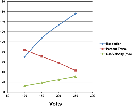
Given the impressive results shown for a small 8 stage PFDMA, it is interesting to calculate and predict the performance of a larger PFDMA currently being constructed. A 30 stage PFDMA with stages separated by 0.5 mm would require a pumping speed of ∼55–270 L/min for gas velocities ranging from 10–50 m/s, easily attainable using common vacuum cleaner type pumps. For calculations, Ey was set at 50 V per stage or 100 V/mm to ensure high ion transmission (lower Ey will increase the resolution but decrease ion transmission). The results obtained using Simion 8.1’s SDS collision model are shown in Fig. 6 and calculated by stepping Ex voltage and recording the ion signal at the detector. The calculations show that a resolution from ∼70 to ∼155 is possible at Ex voltages ranging from 100 V to 250 V while maintaining a very high ion transmission ranging from ∼83 to 42%. As ion trajectory calculations are in agreement with the experimental results for the 8 stage PFDMA, we are confident that the predictions for the 30 stage PFDMA will be readily attainable, albeit some unforeseen factor, i.e., ion dilution effects or pump stability, limit the device.
A novel DMA termed PFDMA was used to separate ESI formed ions at atmospheric pressure at a resolution approaching 40 in a continuous scanning mode. Due to the PF technique and open arrangement (no exit slit), ion transmission is very high and may approach 100%. In addition, as with traditional DMA’s, the collision cross-sections can be calculated and will be proportional to the applied voltages. According to theory, greater resolutions will be easily attainable by lengthening the total ion path, i.e., increasing the total number of stages with minimal loss in sensitivity. The PFDMA is capable of providing easily interpretable structural information and would find many applications ranging from environmental and biological analysis to explosive or chemical warfare detection. In particular, coupling of a PFDMA with a Mass Spectrometer would result in a very powerful technique providing additional structural information, unambiguous identification, i.e., isomer selection followed by MS/MS applied to Glycomics, and increased peak capacity useful for all -omic analysis.
The authors would like to thank the Genomics Research Center and Academia Sinica for financial support. Technical assistance with Visual Basic Programming from Jung-Lee Lin, is greatly appreciated. The authors would also like to thank NSC under Grant number 102–2325-B-001–001; 102–2113-M-001–002-MY5 and NHRI under grant number NHRI-EX102-9803EI.