Abstract
Core pins and core blocks are frequently used for aluminum alloy die-casting to produce net-shape parts and/or to prevent the parts from shrinkage in thick casting sections. However, for large casting, some other problems such as soldering of core pin due to insufficient cooling, leakage, etc. may also arise. The authors have studied the heat flow from casting to core pin under various casting conditions and developed an efficient cooling system. This paper reports the optimization of thin wall core pin shape from the perspective of heat flow and mechanicals of core pin. The optimum cooling channel diameter of the core pin should be 70 percent of the outer diameter of the core pin. This thin wall core pin in combination with high pressure water cooling would eliminate soldering and would give a longer core pin life than that of conventional solid core pin without internal cooling.
1. Introduction
Aluminum die-casting is universally used for manufacturing complex automobile parts, such as engine blocks, transmission cases, chassis and body parts, due to its low cost, high shape flexibility, good transferability and high productivity. Thus die-casting has become one of the major processes for the automotive parts industry.
On the other hand, higher performance of light weight vehicles demands a more complex shape of the parts. This shape complexity causes many casting defects, such as soldering, leakage and porosity. To deal with these problems, many researchers have studied and developed die materials1–4), surface treatments5–8), die release agents9,10), release agent delivery systems11) and optimization of die design standard for core pin12). The authors have extensively studied the heat flow pattern and surface temperature of core pins by using direct measurement technique and elucidated the effect in order to reduce the inherent problems of aluminum die castings13–16) that are mentioned above.
It has been reported that a thin wall core pin with high pressure water flow is essential to eliminate these casting defects, and film boiling in the cooling channel could be prevented by flowing a large quantity of water15,16).
However, it is still unclear whether a thin wall core pin can withstand the severe production conditions of high pressure die casting e.g. high velocity of the metal flow, high shot cycle time, etc. The purpose of this study is to optimize and verify the shape of thin wall core pins by CAE, considering the mechanicals of core pins.
2. Experiment and Analysis
Due to a difficulty in attaching strain gauges on the wall of a thin cooling channel in a core pin, the stress of cooling channel could not be measured directly. Thus the virtual experiment was carried out, using simulation software named ABAQUS. Linear analysis was adopted for this calculation.
2.1 Verification of CAE result and determination of loading value
Before carrying out the virtual experiment, the accuracy of the computing result was verified by a bending test. A solid core pin was made of alloy tool steel DAC (equiv. SKD61) with heat treatment to harden it up to HRC 47. The loading value from zero to 2 kN was measured by a load cell, and displacement was measured by a displacement gauge as shown in Fig. 1(a). Rosette gauges (1 mm length), were firmly attached to positions indicated as A, B and C on the core pin in Fig. 1(b), and were used to measure the stress. The stresses at the same points were calculated by CAE and were compared with the test results. The constraint condition of this CAE analysis is shown in Fig. 2. Material data used in the computation is shown in Table 1.
Table 1
Material characteristic used in computation.
| |
value |
| material |
DAC (equiv. SKD61) |
| Young's modulus |
206 GPa |
| Poison's ratio |
0.25 |
The experimental stress at point B is measured while loading. The loading value is set just at the stress level value obtained by the S/N curves17) of DAC (equiv. SKD61) between 104 and 105 cycles. In actual operation, core pins are maintained and replaced at the timing of between 104 and 105 shots, so the loading value and loading position is set under same conditions within the life time of the pin. Thus the maximum stress to the base of the core pin for the expected life cycle before rupture could be determined to be no more than 750 MPa from the S/N curves.
2.3 Computing conditions and analytical method
2.3.1 Core pin shape and its strength
Three major factors, such as wall thickness of the core pin (t), fitting clearance between core pin and the insert hole of the die (c), and fitting portion length of the core pin in the die hole (ℓ), which seem to affect the maximum principal stress (here after abbreviated as MPS) were investigated under various conditions. The factors and levels are shown in Fig. 3, where the words shown in bold letters are set as a standard condition to compare with the various analyzing conditions. The constraint conditions and load conditions are shown in Fig. 4. Material data is the same one as shown in Table 1 which was mentioned in previous section 2.1.
2.3.2 Evaluation of MPS on core pin with consideration of die releasing force
Analysis regarding the breakage of core pin mentioned in sections 2.1 and 2.2 is only based on the shrinkage force of casting. However, die releasing force is also known to affect core pin stress. If there is no soldering on the core pin, the authors have estimated die releasing force by eq. (1) based on the elasto-plastic concept reported by Aoyama et al18), and the friction coefficient value “μ” between core pin and casting in eq. (1) is considered to be 0.08 (or 0.16) as suggested by Aoyama et al.
However, when soldering occurs on the core pin surface, excessive ejection force is required to release the casting from the core pin due to adhesions and cracks on the casting surface. In such case, friction coefficient can not be used to estimate the die release force because it does not originate from friction force but from high temperature shear stress of the casting. Unfortunately, no data was available for the high temperature shearing strength of ADC12 aluminum alloy. Therefore, the authors have estimated shearing strength τB induced by the tensile strength σB as shown in eq. (2).
| \[F = 2\pi \times a \times \ell \times \mu \times Y \times \ln (b/a)\] | (1) |
| \[\tau_B = \sigma_B/\sqrt{3} \approx 0.5\sigma_B\] | (2) |
| \[Y = 72.8 + 70.9 \times \cos (0.00582 \times (T - 273))\] | (3) |
Where,
F: releasing force
a: outer diameter of core pin
b: boss diameter of casting: (where b is set 30 mm for boss diameter of casting.)
ℓ: fitting portion length between core pin and casting
μ: friction coefficient between core pin and casting,
Y: high temperature yield strength of core pin (function of the temperature)18)
Taking into account the bending stress and tensile stress arising from die releasing force, the total stresses generated on ϕ10 mm core pins, two of them solid and the other two having a ϕ7 mm cooling channel, were calculated assuming the presence and absence of soldering. Similar calculations were done on two different diameter ϕ7 mm core pins, one is solid and the other has a ϕ4.9 mm cooling channel. Calculating the releasing force, the boss diameter is set to be ϕ30 mm. The analytical conditions are shown in Table 2(a) for variable conditions and Table 2(b) for fixed parameters.
Table 2
Analysis conditions of estimating maximum core pin stress with shrinkage bending force and releasing force.
| (a) Variable parameter |
| |
1 |
2 |
3 |
4 |
5 |
6 |
7 |
8 |
Case
(a) |
Case
(b) |
Case
(c) |
Case
(d) |
Case
(a) |
Case
(b) |
Case
(c) |
Case
(d) |
Soldering:
Presence or Absence |
A |
P |
A |
P |
A |
P |
A |
P |
Enough cooling:
Presence or Absence |
A |
P |
P |
A |
A |
P |
P |
A |
| Shrinkage Force |
2000 N |
500 N |
| Core pin diameter: (D) |
ϕ10 mm |
ϕ7 mm |
| Inner dia. of core pin: (d) |
Solid |
ϕ7.0 mm |
Solid |
ϕ4.9 mm |
| (b) Fixed parameters |
| |
value |
unit |
|
Mold temp at
mold releasing |
643 |
K |
Tensile strength of
Al-alloy at 643 K |
31 |
MPa |
| Coefficient of friction |
0.16 |
|
| Casting boss dia. |
ϕ30 |
mm |
| Core pin length |
50 |
mm |
| Clearance |
0.05 |
mm |
| Fitting length |
30 |
mm |
3. Experimental Results
3.1 Validation of computer analysis and determination of loading conditions
The relationship between the loads and measured and computed principal stress values are shown in Fig. 5. The measured and computed values showed good agreement over a whole range of the loads, and the computer analysis could be used for optimizing the shape of thin wall core pin.
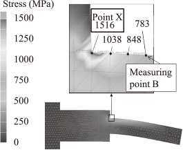
Calculated maximum stress was observed at the base point of the core pin (point X in Fig. 6). The maximum stress was about 1500 MPa, which is twice as high as the aimed value of 750 MPa mentioned in section 2.2.
As a result of this experiment and the above mentioned literature value, a core pin load value of 2 kN and loading point of 15 mm from the base point of the core pin have been considered to be appropriate for the succeeding analysis.
3.2 Core pin thickness and MPS
MPS was calculated under standard conditions by varying the thickness of the core pins. MPS build up locations, and the relationship between MPS and core pin thickness are shown in Fig. 7 and Fig. 8, respectively.


It could be seen from Fig. 7 that the maximum stress in each case invariably builds up at the base of the core pin in the figure. Figure 8(a) shows that MPS decreases drastically with the increase of core pin thickness up to 1.0 mm and then the value stabilizes at a core pin thickness above 1.5 mm, and the MPS for core pin thickness above 1.5 mm match well with that of a ϕ10 mm solid core pin as indicated by the dotted line in the figure. This reveals that mechanical strength similar to a conventional ϕ10 mm solid core pin could be attained with a ϕ10 mm hollow core pin that has a ϕ7 mm internal cooling channel. Furthermore, ϕ7 mm and ϕ5 mm hollow core pins with ϕ4.9 mm and ϕ3.5 mm internal cooling channels will have similar mechanical strengths as those of ϕ7 mm and ϕ5 mm solid core pins, respectively as shown in Fig. 8(b) and (c). Consequently, it can be concluded that there is no significant difference in the bending strengths between solid core pins and hollow core pins with internal diameters no bigger than 70% of their outer diameters.
3.3 Core pin clearance at the fitting section
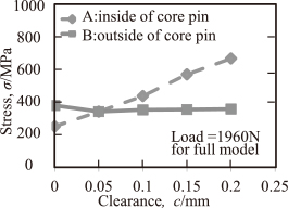
The effect of fitting clearance changes on stress distribution is shown in Fig. 9, whereas “A” indicates the MPS of the inner surface of the core pin, and “B” as that of the outer surface. If the clearance between the core pin and the fitting section is large, stress will not build up significantly on the core pin until it comes in contact with the circumference (inner surface) of the core pin insert hole. However, with the increase of load, once the core pin touches the inner surface of the hole, the MPS point starts shifting gradually from the outer core pin surface to the inner wall of the cooling channel (Fig. 9). This suggests that under high load, initiation of core pin failure can also take place at some predetermined section on the inner wall of the cooling channel. Such failure is often observed in mass production, which could also be enhanced by stress corrosion induced by the presence of dissolved oxygen or air bubbles in the cooling water19,20).

The relationship between MPS and clearance made by the core pin and fitting hole, is shown in Fig. 10. The MPS comes down to the minimum at a clearance of 0.05 mm as shown in Fig. 8. Over 0.05 mm, the MPS increases as the clearance gets wider. This indicates that a suitable clearance should exist where a longer core pin life could be expected.
3.4 Core pin fitting portion length
Figure 11 and Fig. 12 show how the fitting portion length of the core pin affects the MPS. These figures show that the MPS increases gradually from a point where fitting portion length is close to zero and attains the peak value at the length of 10 mm when the stress points are located on the outer surface of the core pin. However, with a further increase in fitting portion length, the MPS starts to decrease gradually and its location shifts towards the end of the fitting section of the core pin.
3.5 Effect of die release force on core pin
The calculated values are shown in Table 3(a) for ϕ10 mm core pins and similarly in Table 3(b) for ϕ7 mm core pins.
Table 3
Estimation of maximum core pin stress calculated with shrinkage bending force and releasing force.
| (a) In case of core pin dia. (D): ϕ10 mm |
| |
Maximum stress (MPa) |
Estimated soldering conditions |
| Bending*1 |
Tensile*2 |
Total |
case (a)
Conventional |
294 |
104 |
398 |
No soldering achieved by special die surface treatment and external cooling |
case (b)
Conventional |
294 |
310 |
604 |
Soldering occurred |
case (c)
Thin wall |
341 |
204 |
545 |
No soldering with high pressure water |
case (d)
Thin wall |
341 |
608 |
949 |
Soldering with no cooling water |
| (b) In case of core pin dia. (D): ϕ7 mm |
| |
Maximum stress (MPa) |
Estimated soldering conditions |
| Bending*1 |
Tensile*2 |
Total |
case (a)
Conventional |
292 |
59 |
351 |
No soldering achieved by special die surface treatment and external cooling |
case (b)
Conventional |
292 |
442 |
734 |
Soldering occurred |
case (c)
Thin wall |
334 |
117 |
451 |
No soldering with high pressure water |
case (d)
Thin wall |
334 |
868 |
1282 |
Soldering with no cooling water |
Note: *1: Bending stress by aluminum shrinking force.
*2: Tensile stress by mold release resistance.
The tables show that in absence of soldering (case (a)) the total stress is the lowest for conventional solid core pins irrespective of their thickness indicating longer core pin life. However, when there will be large casting volumes, like thick bosses around these core pins, the core pin surface temperature will be higher than the solidus temperature of ADC12 alloy for a longer period of time due to insufficient cooling, resulting in soldering and higher total stress (case (b)), which increases the possibility of core pin failure.
The above situation in case (b) can be remedied by using hollow core pins and by flowing an appropriate amount of high pressure water to efficiently remove heat from the boss section so that the core pin surface temperature will drop below the solidus temperature quickly (case (c)). The calculated total stress values in case (c) become lower than those in case (b) suggesting better core pin life under such casting condition. If by any chance, that high pressure water cooling gets interrupted, hollow core pins will overheat causing heavy soldering due to the generation of the highest total stress (case (d)).
4. Discussions
4.1 Durability of thin wall core pin
In earlier studies15,16), the authors have found that if the solid core pin diameters are smaller than ϕ10 mm and the boss diameters are larger than ϕ30 mm, the core pin surface temperature will eventually rise above the solidus temperature causing soldering even if external cooling is intensified.
However, as mentioned in the previous section, by maintaining a large flow of high pressure cooling water in the cooling channel of thin wall core pin, the surface temperature of the core pin could be kept below the solidus temperature rendering the core pin solder free. In order to predict core pin life under these conditions, the present results are plotted on the S/N curves for DAC17) (equivalent to SKD61) as shown in Fig. 13. Case (d) in the figure shows that a thin hollow core pin without cooling has the highest MPS and the lowest core pin life due to insufficient strength. Comparison of case (b) and case (c) reveals that a thin hollow core pin with sufficient cooling has better life than solid one without internal cooling, and that the thinner core pin has the better heat conductivity.

From the point of view of heat conductivity, using a thin wall core pin with cooling is similar to using high thermal conductivity die material. Therefore, in developing high strength and high thermal conductivity die parts for high temperature use, a balance must be struck between material properties and part design.
4.2 Fitting conditions and maximum stress point of core pin
The maximum stress point appears in the core pin and varies according to its fitting conditions. If the fitting clearance is large and the load is small, the core pin can easily deform without any touching to the insert hole. Thus the maximum stress arose at the end of the core pin closet to the step zone. And if the clearance of the fitting portion is small, the core pin will touch on the entrance of the die insert hole, and maximum tensile stress arose at the opposite side to where the core pin touches. The touching point would work as a fulcrum to increase the tensile stress of the outer side of the core pin. In addition, the more the load increases, the more stress in the channel side increases, due to constraint by the insert die hole.
Besides the clearance, fitting portion length might affect the maximum stress and its position. Considering these maximum principal stress behaviors, setting the adequate dimension is highly important for a longer service life of core pin.
Understanding the core pin stress behavior would be important for the designing of core pins for the die design engineers.
4.3 Maximum stress on cooling channel and cooling water quality
Depending on the fitting clearance and the fitting portion length, the MPS build up point may shift from the outer core pin surface to the cooling channel inner wall. In case the MPS point appears on the inner wall of the cooling channel, low pH cooling water will certainly accelerate stress corrosion19,20) at this point, which would drastically lower the core pin life as mentioned in section 3.3. On the other hand, if the water contains high amount of silica, magnesia or carbonates, they will quickly deposit in the cooling channel. Partially or completely clogged cooling channel hampers heat transfer giving rise to cause soldering and core pin failure. Consequently, it is necessary to pay close attention to the purity of cooling water when using the thin wall core pin.
5. Conclusion
The thin wall core pin development for use in high pressure die casting presented in this report has shown that the bending stress caused by shrinkage of casting would vary under different constraint conditions, and in some cases, the maximum value would appear on the cooling channel surface.
The maximum principle stress builds up on a thin wall core pin, but when its inner cooling channel diameter is no larger than 70% of the outer diameter, it is similar to that of the solid core pin having the same outer diameter.
When used in conjunction with an appropriate volume of high pressure water flow, the thin wall core pin will have higher cooling efficiency, less soldering and longer life than a solid core pin with external cooling.
REFERENCES
- 1) M. Hihara: Die & Mould Technology 24 (2009) 18–24.
- 2) M. Kohno and K. Inoue: Materia Japan 48 (2009) 32–34. 10.2320/materia.48.32
- 3) M. Kohno: Die & Mould Technology 28 (2013) 28–31.
- 4) M. Nagasawa: Die & Mould Technology 28 (2013) 32–35.
- 5) H. Nomura: JSTP 56 (2015) 171–175. 10.9773/sosei.56.171
- 6) N. Nihira, Y. Tamura, K. Namiki, M. Ikenaga, K. Yashiro, M. Shiratori, Y. Kumagai, K. Kawada, M. Sasaki, R. Shimpo and M. Kawaguchi: Minor Special Issue on Recent Surface Treatment for Dies and Molds, JSTP 50 (2009) 592–642.
- 7) Y. Furukawa: Die&Mould Technology 29 (2014) 24–28.
- 8) H. Shima, H. Onishi, Y. Kondo, K. Yamagishi, M. Yamashita and T. Takahashi: Trans. Japan Die Casting Congress (2008) 67–70.
- 9) R. Izawa, K. Togowa, H. Ohira, M. Kobayashi and I. Yamaguchi: Trans. Japan Die Casting Congress (2004) 77–84.
- 10) Y. Hama, I. Ishimaru, K. Ikebata and M. Sueyoshi: Trans. Japan Die Casting Congress (2010) 49–54.
- 11) T. Ishikawa, S. Ukai, S. Hayafuji, M. Kondo and K. Maehara: Trans. Japan Die Casting Congress (2014) 37–41.
- 12) T. Ozeki and Y. Matsuo: Mazda Technical Review 26 (2008) 165–169.
- 13) K. Shirahige, Y. Hatamura, S. Takeda and Y. Mochiku: Trans. Japan Die Casting Congress (1986) 123–130.
- 14) Y. Hatamura, K. Shirahige, Y. Mochiku and S. Takeda: Trans. NADCA (1989) paper No. G-T89-023.
- 15) S. Takeda and S. Orii: JILM 65 (2015) 224–228. 10.2464/jilm.65.224
- 16) S. Takeda and S. Orii: JILM 66 (2016) 124–129. 10.2464/jilm.66.124
- 17) Hitachi Metals Ltd.; Catalog, HY-B8(J,E)-R, (2011)
- 18) S. Aoyama, H. Sugitani, K. Sakamoto and T. Umemura: JILM 43 (1993) 275–280. 10.2464/jilm.43.275
- 19) F. Hine: J. Japan Society of Materials Science 26(290) (1977) 1124–1129. 10.2472/jsms.26.1124
- 20) Y. Furukawa, H. Uebayashi and K. Suzuki: J. Japan Foundry Engineering Society 80 (2008) 245–250.