Abstract
Steel plate with tensile strengths of from 440 MPa to 980 MPa is increasingly being adopted for the structural elements of automobile bodies to both reduce weight and increase collision safety. However, the use of such material brings defects in press forming and other problems. The research reported here focuses on the form-forming method, which is effective for forming high tensile strength steel plate. To clarify the features of form-forming, we used eight types of steel plate having tensile strengths of from 270 MPa to 980 MPa in three forming processes, draw-forming, one-step form-forming, and two-step form-forming, to evaluate the shape freezing property. The results showed that the shape freezing property depends on the mechanical properties of the material; specifically, a correlation with tensile strength, 0.2% proof stress, and elongation was seen. The effectiveness of form-forming for materials of higher strength was confirmed. Improved shape freezing by dividing the form-forming process into two steps was also confirmed. For draw-forming, the entire shaped surface was affected by unbending, so form-forming effectively suppresses unbending. The spatial distribution of unbending was evaluated quantitatively by measuring the residual stress distribution, confirming that residual stress serves as a useful index for clarifying the forming mechanism.
1. Introduction
The latest trend in automobile body manufacture involves reducing weight to conserve energy in relation to environmental concerns. At the same time, however, there is a need for higher collision safety to protect vehicle occupants. Higher collision safety requires an increase in the amount of energy absorbed by the body in a collision, which is achieved by using body structural components of greater cross-section and thicker plate material to increase body strength. That, however, also increases body weight. There is thus a trade-off between automobile body weight reduction and collision safety. To overcome that problem, high tensile strength steel plate is being adopted to maintain the required body strength and amount of energy absorbed while contributing to weight reduction through use of thinner material than the conventional mild steel plate (about 270 MPa).
For those reasons, high tensile strength steel plate of from 440 MPa to 980 MPa is being used for the body structural elements. However, the use of high tensile strength steel plate results in press forming defects (spring-back, vertical wall warping and twisting) as well as cracking and creasing, higher process noise, the need for greater forming pressure, and many other problems. To counter those problems, part shape straightening and forming method are being improved1–4).
Nevertheless, the most important problem when high tensile strength steel plate is used is dimensional accuracy, and the focus in process technology research is on ways to improve shape accuracy5–13). The basic approach is to give the die a shape that differs from the actual part shape so that the part has the specified shape (dimensions) after spring-back, a technique called 'anticipation'. A technique to control the internal stress of the material at bottom dead center of the forming has also been proposed and is close to being made practical14,15). Another approach is to analyze the forming method and material behavior by FEM simulation16–20), but all of those methods ultimately ensure dimensional accuracy by iterative adjustments of the die through trial and error, and for some product shapes, the dimensional accuracy cannot be ensured.
The research described here focuses on the form-forming method, which is effective for shaping high tensile strength steel plate. The form-forming described here and the draw-forming that has often been used previously are illustrated in Fig. 1. Draw-forming involves constraining the periphery of the material and pressing the material into the die. Form-forming, on the other hand, constrains the center part of the material and allows the periphery of the material to move freely. To clarify the features of form-forming, we fabricated experimental dies for actual automobile part shapes and did basic research on the forming mechanism. We also fabricated test dies for draw-forming to compare process accuracies and the forming mechanisms. Eight test materials ranging from mild steel (tensile strength of 270 MPa) to ultra-high tensile strength steel (tensile strength of 980 MPa) were used in the experimental evaluation of the forming mechanism.
2. Testing method
2.1 Test specimens
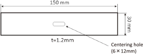
The test specimens (Table 1) include eight types of commercially available steel plate that range from 270 MPa mild steel to 980 MPa high tensile strength steel. All specimens have a plate thickness of 1.2 mm.
Table 1
Mechanical properties of tested materials.
| Material |
Tensile strength
(MPa) |
0.2% proof stress
(MPa) |
Elongation
(%) |
| JSC270E |
280 |
126 |
55 |
| JSC440W |
455 |
320 |
34 |
| JSC590R |
630 |
453 |
30 |
| JSC590Y |
589 |
369 |
34 |
| JSC590T |
620 |
425 |
38 |
| JSC780Y |
806 |
436 |
24 |
| JSC780T |
848 |
494 |
32 |
| JSC980Y |
1009 |
693 |
16 |
Specimens with the geometry illustrated in Fig. 2 were used in press forming experiments that assumed the shape of automobile parts shown in Fig. 3. The two types of experimental form-forming dies13) shown in Fig. 4 and the draw-forming die shown in Fig. 5 were fabricated for the experiments. The pad pressure in form-forming is 6.94 kN and draw-forming is 14.8 kN. Forming end condition is in bottom dead center stroke control used to 35 spm speed. The die drawings are shown in Fig. 6.
The form-forming experiments included one-step forming, in which the target shape is formed in a single processing step, and two-step forming. Together with the draw-forming process, three forming processes were tested in total. The 1078 kN mechanical press shown in Fig. 7 was used for the forming.
2.3 Shape freezing evaluation method
Shape freezing is evaluated by measuring the camber angle of the vertical wall after the experimental forming. The camber angle (θc in eq. (1)) is measured as the angle formed by the web surface and the upper and lower parts of the wall (Fig. 8).
| \[
\theta_{\rm C} = \theta_{1} - \theta_{0}
\] | (1) |
The residual stress from each of the forming processes (one-step form-forming, two-step form-forming and draw-forming) was measured by x-ray diffraction at five locations (Fig. 9) on the front and back sides of the material, for a total of 10 measurements. The x-ray beam diameter was 1 mm. The beam was produced by an x-ray tube using Cr for measuring the Fe (211) plane. And average penetration depth of X-ray is a few micrometers. We used the x-ray diffraction is Auto Mate M made by Rigaku.
3. Test Results (Shape Freezing for the Various Forming Methods)
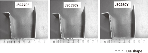
The shape freezing results for the three forming methods and each type of steel are presented in Figs. 10, 11 and 12. We can see that the shape freezing is better for the lower-strength materials that are easily formed, such as JSC270E, and worse for the higher-strength steels that are more difficult to process, such as JSC980Y.
From the results for each forming method applied to JSC980Y, for which shape freezing was the worst (Fig. 13), we can see that two-step form-forming produced the best shape freezing. The shape freezing in the lower part is better with one-step form-forming, but draw-forming produces better results in the upper part.

The relationships of the camber angle (θc) and the mechanical properties (tensile strength, 0.2% proof stress, and elongation) after forming by each method are presented in Figs. 14, 15 and Fig. 16. We see that the camber angle, which indicates the degree of shape freezing, is larger (shape freezing is degraded) for materials of higher tensile strength. The same relationship holds with the 0.2% proof stress as well. It is a spurious correlation, but we described the relationship with elongation for reference. The tendency is for materials that have higher elongation to be associated with smaller camber angles (better shape freezing). It is thus clear that the mechanical properties and shape freezing are related.
4. Discussion (Explanation of the Forming Mechanism)
The reason for the differences in shape freezing among test specimens is considered to be that the spring-back (elastic recovery) phenomenon varies with the type of steel. That can be inferred from the relationships of the camber angle and the mechanical properties shown in Figs. 14, 15, and 16. The reason for the differences in shape freezing that occur according to forming method even for the same steel material is considered to be that the amount of unbending that the material experiences during forming differs.
Comparing the illustrations of the different forming methods in Fig. 17, we can understand how the forming processes differ. The deformation behavior during draw-forming is shown in Fig. 18. Although there is a bending stress at the die shoulder (compressive stress on the die side), unbending (tensile stress) occurs at the bend as the forming proceeds. That unbending is considered to act on the entire wall part of the forming surface in draw-forming. The deformation behavior during one-step form-forming is shown in Fig. 19. At the beginning of the forming, the state is nearly simple bending at the sides of the web, but as the material is pushed deeper into the die, a unbending stress begins to act between the end of the punch and the shoulder of the die. Because the unbending stress is larger for larger curvatures, the camber increases toward the flange. From the deformation behavior of the material in two-step form-forming shown in Fig. 20, we can see that that dividing the process into two steps eliminates the effect of unbending in the vertical wall section, resulting in a forming mechanism that is close to simple bending. The shape freezing is therefore considered superior. The effectiveness of form-forming was also confirmed by Yoshida et al.21), but we obtained knowledge to further improve shape freezing by dividing the form-forming process.


For a quantitative evaluation of the unbending that affects the material during forming, we measured the residual stress distribution in the vertical wall section where the distortion occurred. The results for JSC980Y are presented in Figs. 21, 22 and 23. From Fig. 21, we see that residual stress of about 400 MPa over the entire side wall on both the front and back sides of the material was confirmed, verifying that a large unbending effect is at work on the entire side wall in draw-forming. Looking at the results for one-step form-forming (Fig. 22), we see that there is a tendency for the residual stress to increase toward the flange. That can be considered to indicate that the unbending increases as the distance to the flange decreases (Fig. 19). Looking at the two-step form-forming shown in Fig. 23 in the same way, we see that the overall residual stress is low. That fact verifies the superiority of the split-process forming method in eliminating unbending. It was found that the difference of the processing load tendency in each forming method22) and the way of material flow during forming13) corresponds to the residual stress distribution. So, measuring the residual stress distribution in this way makes it possible to evaluate the forming mechanism.

5. Conclusion
We evaluated shape freezing for three forming methods, draw-forming, one-step form-forming and two-step form-forming, using steel plate materials that ranged in tensile strength from 270 MPa to 980 MPa. We also quantitatively evaluated the unbending phenomenon, which relates to shape freezing, by measuring the residual stress in the material after forming.
The results are summarized below.
(1) The shape freezing was dependent on the material, varying with the material mechanical properties. A correlation with the tensile strength, 0.2% proof stress, and elongation properties was observed, and the effectiveness of the form-forming method for materials of higher tensile strength was confirmed.
(2) Dividing the form-forming method into two process steps was confirmed to produce good shape freezing.
(3) For the draw-forming method, there was unbending over the entire shaped surface, whereas form-forming method controlled unbending. For form-forming, also, unbending can be reduced greatly by dividing the forming process into two steps.
(4) Quantitative evaluation of the unbending sites confirmed that unbending can be evaluated by measuring the residual stress distribution, which can serve as an index for the forming mechanism.
REFERENCES
- 1) X. Xue, J. Liao, G. Vincze, J. Souse, F. Barlat and J. Gracio: Mater. Des. 90 (2016) 204–217. 10.1016/j.matdes.2015.10.127
- 2) I. Gil, J. Mendiguren, L. Galdos, E. Mugarra and E.S. de Argandona: Tribol. Int. 103 (2016) 266–273. 10.1016/j.triboint.2016.07.004
- 3) S.F. Golovashchenko, A.J. Gillard, A.V. Mamutov and R. Ibrahim: J. Mater. Process. Technol. 214 (2014) 2796–2810. 10.1016/j.jmatprotec.2014.01.012
- 4) A.D. Santos and P. Teixeira: J. Mater. Process. Technol. 199 (2008) 327–336. 10.1016/j.jmatprotec.2007.08.039
- 5) W. Wang, Y. Zhao, Z. Wang, M. Hua and X. Wei: Tribol. Int. 93 (2016) 17–28. 10.1016/j.triboint.2015.09.011
- 6) J. Lee, F. Barlat and M. Lee: Int. J. Plast. 71 (2015) 113–135. 10.1016/j.ijplas.2015.04.005
- 7) M. Tisza and Z. Lukacs: Procedia Eng. 81 (2014) 975–980. 10.1016/j.proeng.2014.10.127
- 8) R.H. Wagoner, H. Lim and M. Lee: Int. J. Plast. 45 (2013) 3–20. 10.1016/j.ijplas.2012.08.006
- 9) T. de Souza and B.F. Rolfe: Int. J. Mech. Sci. 68 (2013) 236–245. 10.1016/j.ijmecsci.2013.01.021
- 10) H. Lim, M.G. Lee, J.H. Sung, J.H. Kim and R.H. Wagoner: Int. J. Plast. 29 (2012) 42–59. 10.1016/j.ijplas.2011.07.008
- 11) S. Nishino and K. Ohya: Mater. Trans. 52 (2011) 452–457. 10.2320/matertrans.F-M2010828
- 12) P. Chen and M. Koc: J. Mater. Process. Technol. 190 (2007) 189–198. 10.1016/j.jmatprotec.2007.02.046
- 13) S. Nishino, K. Ohya and K. Naruishi: JSAE Review 24 (2003) 283–288. 10.1016/S0389-4304(03)00048-1
- 14) L. Komgrit, H. Hamasaki, R. Hino and F. Yoshida: J. Mater. Process. Technol. 229 (2016) 199–206. 10.1016/j.jmatprotec.2015.08.029
- 15) K. Lawanwomg, H. Hamasaki, R. Hino and F. Yoshida: Procedia Eng. 81 (2014) 957–962. 10.1016/j.proeng.2014.10.124
- 16) H.U. Hassan, H. Traphoner, A. Guner and A.E. Tekkaya: Int. J. Mech. Sci. 110 (2016) 229–241. 10.1016/j.ijmecsci.2016.03.014
- 17) X. Xue, J. liao, G. Vincze, A.B. Pereira and F. Barlat: Int. J. Mech. Sci. (2016) 1–15. 10.1016/j.ijmecsci.2016.08.003
- 18) A. Ghaei, D.E. Green and A. Aryanpour: Mater. Des. 88 (2015) 461–470. 10.1016/j.matdes.2015.09.012
- 19) B. Chongthairungruang, V. Uthaisangsuk, S. Suranuntchai and S. Jirathearanat: Mater. Des. 50 (2013) 253–266. 10.1016/j.matdes.2013.02.060
- 20) P.A. Eggertsen and K. Mattiasson: Int. J. Mech. Sci. 51 (2009) 547–563. 10.1016/j.ijmecsci.2009.05.007
- 21) T. Yoshida, E. Isogai, K. Hashimoto, T. Katayama and Y. Kuriyama: J. Jpn. Soc. Technol. Plast. 46-534 (2005) 656–660.
- 22) S. Kanno, T. Hasegawa, S. Nishino, K. Ohya, K. Kanno and Y. Komine: JSAE Review 33-12 (2012) 1–4.