Abstract
Sub-micrometer diameter Cu particles fabricated in air by wet synthesis at 80℃ for 2 h were immersion plated with Ag to produce an inexpensive conductive paste filler aimed at achieving fine printed patterns. Increasing the volume ratio of hydrazine hydrate to ammonium hydroxide used during wet synthesis was found to accelerate the rate of reduction and increase the yield of Cu particles to as much as 97.56% when an optimal ratio of 3:7 was used. The resulting particles (average size = 0.56 μm) exhibited excellent dispersion, with the use of an optimal Ag concentration of 15 mass% in their subsequent immersion plating producing a continuous Ag shell and a 0.62 μm average diameter. Increasing the Ag concentration beyond this, however, resulted in abrupt agglomeration between the particles, as well as the formation of cavities and spherical pure Ag particles. Those particles produced under optimal conditions experienced only a slight weight increase of 0.4% after 75 min exposure to air at 150℃, suggesting that they have an excellent resistance to oxidation at this temperature.
1. Introduction
With continued focus on reducing materials cost in the packaging of electronics, there has been a recent surge in industrial and academic interest in Ag-coated Cu particles.1–10) The reason for this is that if an Ag coating layer can prevent the Cu oxidizing during curing in air at temperatures less than 200℃, then the Ag-coated Cu particles can be used as a more price competitive alternative to Ag filler materials currently used in the preparation of conductive pastes; i.e., the electrical conductivity of Cu is comparable to that of Ag. Furthermore, this should make it possible to reduce the size of the filler particles to around one micrometer or less, thereby keeping up with the trend in electrode printing toward producing fine patterns with dimensions narrower than the present level of 40–50 μm.
Wet chemical synthesis allows for the preparation of particles with dimensions of one micrometer or less, which cannot be fabricated by the atomization of molten metal, as well as the preparation of particles measuring just nanometers in diameter. A narrow particle size distribution can be ensured by adjusting the conditions of the wet process, thereby eliminating the need for post-process size classification. Of the reducing agents that have been used to induce a fast reduction of metal ions, or reduce the temperature of wet chemical synthesis, hydrazine hydrate has been reported as being a suitable reductant for the fabrication of Cu particles of one micrometer or less in size.11–13) Furthermore, with the addition of a proper dispersing agent, particles synthesized with hydrazine hydrate exhibit excellent dispersion.12)
Immersion plating is a simple wet process that is suitable for applying successive Ag layers onto a Cu core particle. To prevent or suppress the oxidation of a Cu core particle, the preparation of Ag shell completely covering the Cu particle is indispensable. Any discontinuous Ag coating method using Cu core particles dried after the wet synthesis can fail to accomplish complete coating due to surface oxidation, whereas the successive Ag plating will do not. As an example of such a method, Hai et al. synthesized 5 μm-diameter Ag-coated Cu particles and investigated their thermal oxidation properties,9) and yet though they observed dewetting of the Ag layer on the Cu surface as it reacted at temperatures approaching 200℃, the long-term oxidation behavior at 150℃ was not described. Given that the most common curing temperature used for conductive pastes is 150℃, there is clearly a need to examine the oxidation behavior of Ag-coated Cu particles at this temperature.
In this study, Cu core particles with a sub-micrometer diameter and excellent dispersity are first synthesized by an ammonium hydroxide-based chemical synthesis method using hydrazine hydrate and sodium tripolyphosphate. Immediately following the synthesis, immersion plating with different Ag concentrations is continuously conducted and the oxidation resistance of the resulting Ag-coated Cu particles is assessed.
2. Experimental Procedure
The synthesis of the Cu particles was carried out using copper(II) sulfate pentahydrate (CuSO4·5H2O, ≥98.0%) with ammonium hydroxide (NH4OH, 28–30% NH3 base) as the solvent and complexing agent, respectively, hydrazine hydrate (N2H4·xH2O, N2H4 50–60%) as the reductant, and sodium tripolyphosphate (Na5P3O10, 85%) as a dispersant. All chemicals were used as received from Sigma-Aldrich Co. without any further processing or purification.
A detailed procedure for the synthesis of the Cu particles is as follows. First, 1.335 M of copper(II) sulfate pentahydrate and 0.136 M of sodium tripolyphosphate was dissolved in 70 ml of ammonium hydroxide under magnetic stirring for 20 min to produce what is hereafter referred to as Solution I. A second solution (Solution II) was then prepared by mixing 50 ml of hydrazine hydrate in 50 ml of ammonium hydroxide over 20 min of stirring. A 100 ml aliquot of Solution II was then added dropwise to Solution I while stirring within a three-neck flask over 330 s. This flask was then sealed and the mixture heated to 80 or 90℃ with a heating-mantle for 20 min under continuous stirring. Finally, the mixture was allowed to cool to room temperature over 60 min. All of these aforementioned processes were conducted in air. In order to determine the optimal concentration of reductant, this procedure was repeated in full with different volume ratios of hydrazine hydrate and ammonium hydroxide in the 100 ml of Solution II.
To ensure successive plating of the Cu particles with Ag following their synthesis, the reaction mixture (containing residual impurities) was centrifuged at 10000 rpm for 15 min and the ammonium hydroxide solvent was extracted and replaced. This extraction and washing process was performed three times, after which 10 g of the Cu particles was mixed with 170 ml of fresh ammonium hydroxide. A precursor solution was prepared for the Ag plating by dissolving given amounts of silver nitrate (AgNO3, ≥99.5%, Nanjing Chemical Reagent Co.) in 50 ml of ammonium hydroxide for 10 min while stirring. This precursor solution was then added dropwise to the Cu particle mixture under continuous stirring at 300 rpm for 5 min; the complete mixture then being stirred for an additional 2 min. The amount of silver nitrate in the precursor solution was calculated to give Ag contents of 3.75, 7.5, 15, 20, 25, and 30 mass% relative to the total metal weight, which was based on the assumption that the added Ag precursor was fully reduced. Prior to recovering the Cu or Ag-coated Cu particles from solution, they were washed three times using ethanol and separated from the liquid phase by centrifuging at 1000 rpm for 15 min. After decanting the supernatant liquid, the particles were dried in a vacuum chamber at room temperature.
The size and morphology of the fabricated particles were analyzed using a field-emission scanning electron microscope (FESEM, JSM-6700F, JEOL Co.) and their phase composition was determined by X-ray diffraction (XRD, X'pert PRO-MPD, PANalytical). Scanning transmission electron microscopy (STEM, Tecnai G2 F30ST, FEI Co.) was also carried out to determine the quality of the Ag plating layer on a Cu particle in cross section. To evaluate the resistance to oxidation of a conductive paste made from these Ag-coated Cu particles at a typical curing temperature, thermogravimetric-differential scanning calorimetry (TG-DSC, TG-DSC, Q600, TA Instruments) analysis was performed in air at 150℃ with a heating ramp rate of 20℃/min.
3. Results and Discussions
In the synthesis of the Cu particles, the initial chemical reaction is that which occurs during the preparation of Solution I:
| \[
\begin{split}
&Cu^{2+} + {SO_4}^{2-} + 6(NH_3) + H_2O \\
& \quad \to [Cu(NH_3)_4]^{2+} + (NH_4)_2SO_4 + 2OH^-
\end{split}
\] | (1) |
With the addition of Solution II, which contains hydrazine hydrate, Cu
2O particles are formed as an intermediate phase through the reaction:
| \[
\begin{split}
&[Cu(NH_3)_4]^{2+} + 2{SO_4}^{2-} + 2H_2O + 1/2N_2H_4 \\
& \quad \to Cu_2O + 2(NH_4)_2SO_4 + 4(NH_3) + H_2O + 1/2N_2
\end{split}
\] | (2) |
This Cu
2O then slowly transforms into Cu particles through the dissolution of the oxide and the reduction of Cu(I) ions in the presence of remaining hydrazine reductant:
14–16)
| \[Cu_2O + 1/2N_2H_4 \to 2Cu + 1/2N_2 + H_2O\] | (3) |
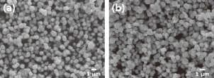
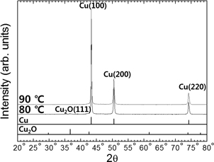
The SEM images in Fig. 1 show Cu particles that were synthesized for 20 min at different temperatures using 0.136 M of sodium tripolyphosphate, thus giving 50 ml of hydrazine hydrate and ammonium hydroxide in Solution II. Note that the particles in both samples have a uniform polygonal shape, but the average size of the particles is slightly different between the two; i.e., the particles synthesized at 80℃ were 0.82 (σ = 0.20) μm in size, while those produced at 90℃ were 0.75 (σ = 0.24) μm. In Fig. 2, we see that the sample synthesized at 80℃ shows some evidence of there still being a small amount of Cu2O phase present, whereas the 90℃ sample shows no indication of any phase other than Cu. This confirms that an increase in process temperature increases the rate of chemical reduction, meaning that the concentration of reduced Cu atoms increases with temperature to a critical super saturation level at which burst nucleation is initiated.17–20) Heating to a higher temperature results in an increase in the number of initial nuclei and a decrease in atoms available for the growth of formed particles, which ultimately means that particles with a smaller average size are obtained when synthesis is conducted at elevated temperatures. Consequently, 90℃ was chosen as most suitable reaction temperature for synthesizing core particles of Cu.
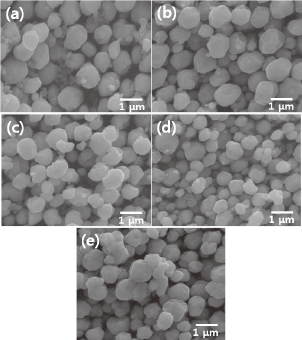
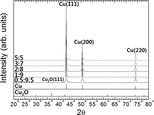
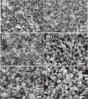
Figures 3 and 4 present SEM images and XRD results, respectively, of particles synthesized at 90℃ for 20 min using different volume ratios of hydrazine hydrate and ammonium hydroxide in Solution II. It is evident in Fig. 3 that the mean size of the particles slightly decreases from 0.83 μm to 0.56 μm with an increase in the hydrazine hydrate to ammonium hydroxide ratio from 0.5:9.5 to 3:7. However, the particle size increased to 0.75 μm when using a ratio of 5:5. The XRD results in Fig. 4 show that the sample produced with a ratio of 0.5:9.5 contains trace amounts of Cu2O phase, whereas only Cu exists in the other samples. A comparison of Figs. 3 and 4 indicates that this trace amount of Cu2O phase exists in aggregates of small particles (~0.2 μm), as shown in Fig. 3(a). This suggests that an increase in the amount of hydrazine hydrate reductant can accelerate the reduction process and can induce more burst nucleation, thereby increasing the number of nuclei17–20) and reducing the final size of the particles. The increase in size observed in the sample with a ratio of 5:5 is attributed to an increase in agglomeration due to collision between primary Cu particles that are explosively formed during synthesis in the absence of a surfactant.21–23)
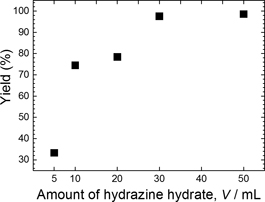
The yield of Cu particles obtained through synthesis at 90℃ for 20 min with different volume ratios of hydrazine hydrate to ammonium hydroxide, as shown in Fig. 5, was calculated by dividing the weight of Cu particles obtained by the weight of Cu in the precursor. This reveals that with an increase in the amount of hydrazine hydrate, the yield of Cu particles is gradually increased. Thus, although 5 ml of hydrazine hydrate in 100 ml of Solution II (hydrazine hydrate:ammonium hydroxide = 0.5:9.5) produces a minimum yield of 33.32%, this increases to 97.56% when the added amount of hydrazine hydrate in Solution II is increased to 30 ml. Beyond this point the yield is saturated, increasing to just 98.57% with the addition of 50 ml of hydrazine hydrate. The optimal ratio of hydrazine hydrate to ammonium hydroxide to use in the synthesis process was therefore determined to be 3:7 based on the purity of the Cu phase, the dispersion of the synthesized particles (Figs. 3 and 4), and the yield (Fig. 5).
Following the synthesis of Cu particles with an optimal ratio of hydrazine hydrate to ammonium hydroxide (3:7) and replacement of the solvent with clean ammonium hydroxide, Ag plating was performed. Given the positive difference in the standard redox potentials of Ag+/Ag0 (+0.799 V) and Cu2+/Cu0 (+0.34 V), galvanic displacement between Ag ions and Cu atoms can be considered spontaneous.5) However, the actual difference in standard redox potential between Ag+/Ag0 and Cu2+/Cu0 will be 0.42 V rather than 0.46 V, as [Ag(NH3)2]+ complex ions (+0.38 V) are also formed during the preparation of the Ag precursor solution.11,24,25) This decrease can improve the stability of the complex and reduces the likelihood of free Ag particles forming in the solution.5,11)
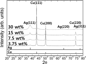
The SEM images and XRD results in Figs. 6 and 7, respectively, show the Cu particles after immersion plating with different Ag contents. It is apparent from this that increasing the amount of Ag in the plating solution increases the intensity of the XRD peaks for Ag, particularly the Ag(111) peak. The particle size, as measured from the SEM images, also generally increases; however, when the Ag content is increased beyond 15 mass% the increased intensity of agglomeration between particles caused by high-speed plating results in an abrupt increase in particle size. For example, the average particle size increased from 0.55 (σ = 0.21) to 0.61 (0.19), 0.62 (0.18), 0.86 (0.40), 0.93 (0.39), and 1.20 (0.30) μm when the Ag concentration of the precursor solution was increased from 3.75 to 7.5, 15, 20, 25, and 30 mass% Ag. Many of the Cu particles plated with the 3.75 mass% Ag solution exhibited holes in their surface coating, which are considered to be the result of repetitive formation and removal of Cu2O or Cu(OH)2 from non-plated areas of the Cu surface.26,27) This incomplete plating of Ag can be explained by inadequate galvanic displacement caused by using an insufficient amount of Ag in the solution. Increasing the Ag content of the precursor solution reduces the non-plated area on the surface of the Cu particles, which is why holes were scarcely observed on particles plated with solutions containing more than 3.75 mass% Ag.
Copper particles plated with a 20 mass% Ag solution [Fig. 6(d)] were found to rupture occasionally. Spherical particles with smooth surfaces were also observed in the samples, with their size gradually increasing with the Ag content of the precursor solution. The composition of these spherical particles can be determined from the cross-sectional back-scattered electron (BSE) images in Fig. 8, which when combined with the XRD results in Fig. 7, reveals that that the white and grey regions are Ag and Cu phases, respectively. Hence, the cross-sectional images of the spherical particles in Fig. 8 reveal them to be a pure Ag phase. These pure Ag particles were readily observed in the sample prepared from a precursor solution of 20 mass% Ag, but grew larger in size when using precursor solutions with 25 and 30 mass% Ag. It is evident from this that an excess of Ag in the precursor induces the creation and growth of free Ag particles during plating. The cross-sectional BSE images of the sample produced from a 20 mass% Ag precursor showed evidence of cavities in the interior of the ruptured particles that are assumed to be formed through an excessive galvanic displacement reaction between [Ag(NH3)2]+ complex ions and Cu atoms due to the high Ag concentration. Thus, an Ag concentration of less than 20 mass% is optimal for preventing the formation of free Ag particles and ruptured particles. The thinness of the Ag plating layer meant that it was not clearly observed, as only some Cu particles exhibited a thick Ag plating layer.
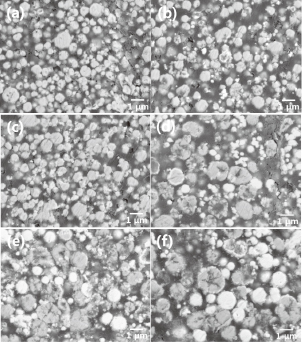
Figure 9 presents cross-sectional element mapping images of Cu particles plated with precursor solutions containing different amounts of Ag. This mapping was not performed in the core of the particle due its size (several hundreds of micrometers), but rather only the surface of the particle was examined. Nevertheless, these images clearly show the existence of the Ag layer on the Cu surface, something that was not easily observed by BSE. We see from this that plating with a 3.75 mass% Ag solution produces an intermittent Ag layer on all of the Cu particles, which is indicative of discontinuous plating. The continuity of the Ag plating layer was enhanced by increasing the solution concentration to 7.5 mass% Ag, but the layer continuity was still deficient. Only when plating with a 15 mass% Ag solution was a near-continuous layer of Ag achieved, as shown in Fig. 9(c); however, this continuity will not be perfect in practice given that the lack of any further reductant addition means that the ionization/dissolution sites of Cu donating electrons will remain. This slight incompleteness to the plating layer could have an effect on the oxidation resistance of the Ag-coated Cu particles, thus having a significant influence on the formation of conduction paths through contacts between filler particles. Full-coverage Ag plating of the Cu particles was approached with an increase in the Ag content in the precursor solution, but this also produced abnormal growth of the Ag layer and the formation of free Ag particles (Figs. 6 and 8). When a reductant is not used, this abnormal process can proceed only through the continuous donation of electrons at sites not plated with Ag. However, this electron donation invariably requires the proportional ionization/dissolution of Cu atoms, which in turn results in the formation of cavities in the interior of the ruptured particles (Figs. 6 and 8).
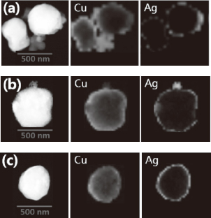
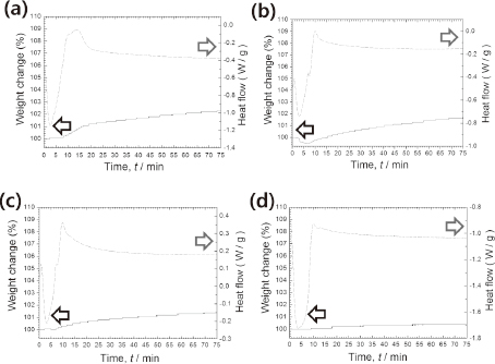
Figure 10 presents a TG-DSC graph for pure Cu particles and Ag-coated Cu particles plated with different Ag precursor solutions in air at 150℃. Interestingly, all samples exhibit an exothermal peak and a gradual increase in weight with oxidation, but the oxidation rate differed between samples. For example, the weight increase of the pure Cu sample was 2.3% after 75 min, whereas the weight increase of the Cu samples plated with 3.75 and 7.5 mass% Ag solutions was much less at 1.6 and 1.4%, respectively. Only a very slight weight increase of 0.4% was measured in the case of the Cu sample plated with a 15 mass% Ag solution, indicating that it has excellent oxidation resistance. However, the slight oxidation that was observed does indicate there are still limitations to the immersion plating process used in this study, in that oxidation can still occur at non-plated areas of the Cu particle's surface. That oxidation will induce a high resistivity in the resultant printed patterns after curing at 150℃. Given that the above-mentioned mechanism of Ag plating, Ag plating methods using a reductant will be more effective in forming full-coverage of Ag shell than present Ag plating only using galvanic displacement.
4. Conclusions
The SEM and XRD analysis has demonstrated that an increase in the volume ratio of hydrazine hydrate to ammonium hydroxide in Solution II from 0.5:9.5 to 3:7 results in a decrease in the average size of particles from 0.83 μm to 0.56 μm, eliminating any trace of the Cu2O phase by accelerating the reduction process. The yield of Cu particles from this optimal solution ratio of 3:7 approached 97.56%, with all particles exhibiting excellent dispersion. The intensity of the Ag peaks in the XRD spectra of Cu particles plated with Ag increased along with the overall particle size as the amount of Ag in the precursor solution was increased to 15 mass%, which indicates the formation of a more developed Ag shell. This was subsequently confirmed through cross-sectional TEM element mapping images. Using a precursor solution containing 15 mass% Ag for plating produced Ag-coated Cu particles with an average diameter of 0.62 μm that had a near-continuous Ag shell. These experienced a weight increase of just 0.4% after oxidation in air at 150℃ for 75 min, which when compared to the 2.3% increase of pure Cu particles, represents an excellent oxidation resistance.
Acknowledgments
This work was supported by Nano-Convergence Foundation (www.nanotech2020.org) funded by the Ministry of Science, ICT and Future Planning (MSIP, Korea) & the Ministry of Trade, Industry and Energy (MOTIE, Korea) [Project Name: Commercialization of 100 Gbps optical receiver and transmitter modules based on nano Ag-coated Cu paste]. The authors also thank Korean Basic Science Institute (KBSI) for the XRD, STEM, and TG-DSC analyses.
REFERENCES
- 1) X. Xu, X. Luo and H. Zhang: Mater. Lett. 57 (2003) 3987–3991. 10.1016/S0167-577X(03)00252-0
- 2) D.S. Jung, H.M. Lee, Y.C. Kang and S.B. Park: J. Colloid Interface Sci. 364 (2011) 574–581. 10.1016/j.jcis.2011.08.033
- 3) J. Zhao, D.M. Zhang and J. Zhao: J. Solid State Chem. 184 (2011) 2339–2344. 10.1016/j.jssc.2011.06.032
- 4) H.T. Hai, J.G. Ahn, D.J. Kim, J.R. Lee, H.S. Chung and C.O. Kim: Surf. Coat. Tech. 201 (2006) 3788–3792. 10.1016/j.surfcoat.2006.03.025
- 5) M. Grouchko, A. Kamyshny and S. Magdassi: J. Mater. Chem. 19 (2009) 3057–3062. 10.1039/b821327e
- 6) Y. Peng, C. Yang, K. Chen, S.R. Popuri, C.-H. Lee and B.-S. Tang: Appl. Surf. Sci. 263 (2012) 38–44. 10.1016/j.apsusc.2012.08.066
- 7) A. Muzikansky, P. Nanikashvili, J. Grinblat and D. Zitoun: J. Phys. Chem. C 117 (2013) 3093–3100. 10.1021/jp3109545
- 8) R. Zhang, W. Lin, K. Lawrence and C.P. Wong: Int. J. Adhes. Adhes. 30 (2010) 403–407. 10.1016/j.ijadhadh.2010.01.004
- 9) H.T. Hai, H. Takamura and J. Koike: J. Alloy. Compd. 564 (2013) 71–77. 10.1016/j.jallcom.2013.02.048
- 10) H.-W. Cui, J.-T. Jiu, T. Sugahara, S. Nagao, K. Suganuma and H. Uchida: Electron. Mater. Lett. 11 (2015) 315–322. 10.1007/s13391-014-4292-2
- 11) D.V. Goia and E. Matijević: New J. Chem. 22 (1998) 1203–1215. 10.1039/a709236i
- 12) W. Songping and M. Shuyuan: Mater. Lett. 60 (2006) 2438–2442. 10.1016/j.matlet.2004.08.051
- 13) P.K. Khanna, S. Gaikwad, P.V. Adhyapak, N. Singh and R. Marimuthu: Mater. Lett. 61 (2007) 4711–4714. 10.1016/j.matlet.2007.03.014
- 14) J.L.C. Huaman, K. Sato, S. Kurita, T. Matsumoto and B. Jeyadevan: J. Mater. Chem. 21 (2011) 7062–7069. 10.1039/c0jm04470a
- 15) M. Blosi, S. Albonetti, M. Dondi, C. Martelli and G. Baldi: J. Nanopart. Res. 13 (2011) 127–138. 10.1007/s11051-010-0010-7
- 16) S.-S. Chee and J.-H. Lee: J. Mater. Chem. C 2 (2014) 5372–5381. 10.1039/c4tc00509k
- 17) V.K. LaMer and R.H. Dinegar: J. Am. Chem. Soc. 72 (1950) 4847–4854. 10.1021/ja01167a001
- 18) V.K. Lamer: Ind. Eng. Chem. 44 (1952) 1270–1277. 10.1021/ie50510a027
- 19) B.K. Park, S. Jeong, D. Kim, J. Moon, S. Lim and J.S. Kim: J. Colloid Interface Sci. 311 (2007) 417–424. 10.1016/j.jcis.2007.03.039
- 20) S.I. Cha, C.B. Mo, K.T. Kim, Y.J. Jeong and S.H. Hong: J. Mater. Res. 21 (2006) 2371–2378. 10.1557/jmr.2006.0285
- 21) C.Y. Lin, U.S. Mohanty and J.H. Chou: J. Alloy. Compd. 501 (2010) 204–210. 10.1016/j.jallcom.2010.04.111
- 22) C. Wang, R. Lv, Z. Huang, F. Kang and J. Gu: J. Alloy. Compd. 509 (2011) 494–498. 10.1016/j.jallcom.2010.09.078
- 23) S.-S. Chee and J.-H. Lee: Electron. Mater. Lett. 8 (2012) 53–58. 10.1007/s13391-011-0510-3
- 24) M.J. Dignam and D.B. Gibbs: Can. J. Chem. 48 (1970) 1242–1250. 10.1139/v70-205
- 25) N.S. McIntyre, S. Sunder, D.W. Shoesmith and F.W. Stanchell: J. Vac. Sci. Technol. 18 (1981) 714–721. 10.1116/1.570934
- 26) D.W. Shoesmith, S. Sunder, M.G. Bailey, G.J. Wallace and F.W. Stanchell: J. Electroanal. Chem. 143 (1983) 153–165. 10.1016/S0022-0728(83)80261-7
- 27) J.H. Kim and J.-H. Lee: Kor. J. Mater. Res. 24 (2014) 617–624. 10.3740/MRSK.2014.24.11.617
