Accurate Evaluation of Copper Alloy Fluidity Using Automatic Pouring Equipment with Improved Pouring Cup Heat Insulation
2017 Volume 58 Issue 4 Pages 629-634
Details
2017 Volume 58 Issue 4 Pages 629-634
New pouring equipment was developed for the measurement of copper alloy fluidity. The fundamental characteristics of the developed equipment are the pouring cup system, which has high heat-retention, a stopper system without preheating, and a pouring temperature determination system. In the evaluation of the developed device, the temperature of the molten copper alloy was decreased by 30 K from pouring to the stability of the measurement of the molten alloy temperature in the pouring cup. The rate of temperature decrease of the molten copper alloy in the pouring cup until the pouring temperature was 3.5 K/s. Experimentally obtained results demonstrated that the linearity between the superheat above liquidus temperature and flow length improved compared with that reported from earlier studies. The standard deviation of flow length in the equipment was 20 mm. These results indicate that the effect of the casting conditions on flow length of the copper alloys will be evaluated accurately with the developed equipment.
This Paper was Originally Published in Japanese in J. JFS 87 (2015) 855–860.
For production of high-quality castings, molten metal should be filled without causing a short run. In this regard, various influential factors of casting conditions upon fluidity of the molten metal have been investigated to date. Fluidity evaluation methods of two types have been used. One method is the MIT method1), by which a quartz tube is inserted into the molten metal to extract it under reduced pressure and to measure the distance along which the molten metal flows. One example of the other method is spiral-type fluidity testing2–8), by which molten metal is poured into a sand mold or die having a spiral-shape cavity. Then the flow length is measured. We used spiral-type fluidity testing in a sand mold, which is closer to actual casting conditions of the copper alloys compared with the MIT method.
For the evaluation of fluidity of casting aluminum alloy, Isobe et al.2) used a shell mold having a spiral-shape cavity and a device with stopper made of Isolite having high heat insulation property and pouring cup. With this device, aluminum alloy is poured into a pouring cup installed directly above the pouring gate of shell mold, a stopper is drawn out at the point at which the molten metal temperature reached a target temperature while visually checking the indication of thermocouple fixed in the pouring cup. Pouring into the mold is performed. Then the flow length is measured. Additionally, some researcher tried to produce a device that provides good reproducibility for the evaluation of the aluminum alloy flow length. Sabatino et al.5) developed an automatic pouring device by which a stopper will open automatically when the molten metal temperature in the pouring cup reaches a predetermined pouring temperature. Using this device, they evaluated the fluidity of ASTM A356.0 alloy and obtained results with good reproducibility. Bouska6) also developed a fluidity testing device equipped with an automatic pouring mechanism and investigated the influences of casting conditions upon the fluidity of Al-Si alloy. In these studies, a device with an automatic pouring mechanism is used. Therefore, opening of the stopper is unaffected by the skill of individual worker, thereby providing results with good reproducibility.
For copper alloy, a spiral-type fluidity testing device identical to that used by Isobe et al. has been used7–9). Japan Non-Ferrous Alloy Casting Association used the spiral-type fluidity testing device in the development of lead-free copper alloy and evaluated the influences of the degree of superheat upon fluidity of various copper alloys9). Influences of the degree of superheat upon fluidity have been investigated empirically and theoretically. Those investigations have revealed that the degree of superheat and flow length can be represented as the following Equation10).
| \[L_f = \frac{\rho [c(\theta_c - \theta_L) + f_c H_f] wS}{h(\theta_L - \theta_0) C}\] | (1) |
However, results of tests performed by Japan Non-Ferrous Alloy Casting Association included a considerable degree of scattering and showed poor correlation between the flow length and superheat (Correlation coefficient R = 0.638–0.994). Their results indicates that if the fluidity evaluation testing device used for aluminum alloy were used with no modification for the evaluation of fluidity of copper alloy, then the fluidity might not be evaluated correctly. A possible cause for scattering in the results obtained using the fluidity testing device is that the timing of pouring is determined by visual confirmation of the digital display of the thermocouple output. Therefore, pouring into a spiral-cavity shell mold at the predetermined target temperature is difficult if the molten metal temperature is reduced rapidly, thereby reducing the accuracy of the experimentally determined pouring temperature. Furthermore, if opening of the stopper is attempted manually, then the stopper should be held by human hands. For that reason, molten metal might leak before opening, resulting in less flow length in some cases.
As difficulties specific to copper alloys, the evaporation amount of zinc, a constituent of many copper alloys, becomes greater if the degree of superheating is high. That difficulty suggests that an upper limit exists for the superheating from a target temperature. Fluidity tests are normally performed varying a degree of superheat from the liquidus temperature as a parameter. Therefore, the range of temperatures at which experiments can be conducted becomes narrower if temperature reduction is excessive when pouring the molten metal in the pouring cup. In addition, the experimental temperature itself is high compared with that of aluminum alloys. Therefore, the temperature of molten metal in the pouring cup decreases rapidly. The heat insulation performance of the pouring cup must be increased. Another problem is that the copper alloy melting temperature is higher than that of aluminum alloy. Therefore, anti-thermal shock properties of the pouring cup and stopper must be improved.
To overcome these difficulties, Ozasa et al.11) developed a new spiral-type fluidity device for copper alloy. They improved the anti-thermal shock properties of the device and the heat insulation performance of the pouring cup that consisted of a steel shell, a heat-insulate sleeve, and a heat-insulate board. However, the Japanese Industrial Standard (JIS) CAC406 alloy flow length measured using this spiral-type fluidity testing device under the same experimental conditions is 236–485 mm, which suggests considerable scattering. For that reason, accurate results were not obtained. A shortcoming of the device developed by Ozasa et al. is that the accurate pouring temperature is not obtained when the molten alloy temperature in the pouring cup is reduced rapidly because the worker visually checks an indication of the thermocouple output to ascertain the pouring temperature. The degree of worker proficiency for manual opening by lifting up the stopper is also considered to be responsible. The graphite bar without pre-heating was used as the stopper before each experiment. This might lead to produce irregularities of the molten alloy temperature in the pouring cup, thereby affecting the results. However, preheating of the stopper is not preferred from the perspective of experimental efficiency and reproducibility. In addition, they did not discuss the issue of the extent to which the degree of superheat can be suppressed for pouring temperatures to the mold. This issue is extremely important for fluidity testing device for copper alloy from the perspective of the vaporization of zinc. However, no mention of this evaluation item is made in their report.
The discussion presented above has revealed the following requirements, which must be met for fluidity evaluation testing devices for copper alloy: The pouring cup must retain heat and be resistant to thermal shock during pouring the molten alloy into the cup. Some mechanism must secure the stopper by other than manual means and must allow opening. Some mechanism must be provided to allow molten alloy temperature measurements in the pouring cup and to allow recording of temperatures when the molten metal is poured into the spiral-cavity shell mold. Experiments should be conducted without stopper preheating. However, no copper alloy testing device that satisfies all of these requirements has been reported in the relevant literature.
For this study, we attempted development of a device that satisfies all of these requirements. For assessment of the heat insulation performance of the device to be developed, we evaluate the temperature reduction of the molten copper alloy from pouring the molten copper alloy into the pouring cup to exhibiting the maximum temperature of thermocouples mounted in the pouring cup. Temperature reduction rate of the molten alloy retained is also evaluated until it is poured into the mold. To determine the pouring temperature correctly, we evaluate the pouring temperature determination mechanism when the stopper is lifted up. Moreover, scattering of the flow length under identical conditions is evaluated. Then influences of the degree of superheating above liquidus temperature on flow length are evaluated. We then demonstrate that the developed device is suitable for evaluation of the fluidity of copper alloy.
Regarding difficulties that arise when the fluidity evaluation testing device for aluminum alloy described above is applied to copper alloy, anti-thermal shock properties and durability of the pouring cup are improved by the heat insulation sleeve, heat insulation board, and steel shell. Moreover, heat retaining performance is improved by the use of a large capacity pouring cup. An air cylinder is used for stopper fixing and lifting up to minimize scattering of the measurement results attributable to differences in the degree of proficiency of different workers. A signal of the piston rod working timing detected by a sensor (auto-switch) is output. Simultaneously, the melting temperature in the pouring cup is recorded to prevent errors in molten alloy temperature determination attributable to visual confirmation of the thermocouple output by a worker.
Figure 1 depicts the device we developed, consisting primarily of a pouring cup, stopper and air cylinder, and a shell mold having a spiral-cavity. Figure 2 presents details of the pouring cup, which consists of a heat-insulation sleeve (Isolite sleeve #1260; Isolite Insulating Products Co. Ltd.), heat-insulation board (Isolite board #1260; Isolite Insulating Products Co. Ltd.) having the ϕ18 mm penetration hole for molten metal flowing from the pouring cup to the shell mold, and a steel shell. A jig is also provided for insertion and fixing of two thermocouples from above the molten metal surface. Averages of temperatures measured by two grounding type sheath thermocouples (K-type, T35051; Sakaguchi EH VOC Corp.) having ϕ0.5 mm sheath diameter and 100 mm length are used as the molten alloy temperature in the pouring cup. The pouring cup is moved by sliding on the guide of stand and proper to allow easy fixing and removal. A lever for lifting up and down the pouring cup is provided to the stand, which is used for setting of the pouring cup and for removal of the remaining molten metal in the pouring cup after flowing of the molten metal ceases.
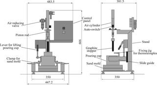
Schematic illustration of the equipment developed for fluidity measurement.

Interior dimensions of the pouring cup and shell mold.
The graphite stopper is fixed to the piston rod. In the mechanism, the stopper is moved upward by manipulating the switch on the operation panel. The molten metal in the pouring cup is poured into the shell mold. A sensor is provided for the air cylinder to output a voltage signal while the piston rod is moving. This voltage signal is read simultaneously with measurement by the thermocouple (sampling time: 100 ms) so that reading of molten alloy temperature at opening of the stopper can be read out from the measurement record after completion of the experiment. As presented in Fig. 2, the graphite stopper must be set in advance at the predetermined location in the pouring cup, and preheating is difficult because of the structure. Therefore, reduction in the molten alloy temperature at pouring the molten alloy into the pouring cup presents a concern. In fact, experimentally obtained results that will be discussed later show that reduction in the molten alloy temperature are significant. Then, for the improvement of molten alloy temperature reduction rate, we attempted to reduce heat transfer from the molten metal to the stopper by winding heat-insulation wool (5 mm thickness, IBI wool blanket #1260, Isolite Insulating Products Co. Ltd.) around the stopper in advance, as depicted in Fig. 3.

(a) Original stopper and (b) improved stopper with insulation.
Figure 4 portrays a shell mold, with a spiral-cavity, used in the test. It has flow length of 1,850 mm. The upper face of the upper mold has a server-like configuration to prevent dropping of molten metal removed from the pouring cup from the upper surface of the mold when it is discharged after flowing ceases. Although back pressure is generated during pouring, which might affect measurement of the flow length, the gas vent hole is not provided specifically to the shell mold considering that gas will be vented from the partition to some degree. Figure 5 presents the external appearance of actual device.

Spiral shell mold used for fluidity tests.

Equipment developed for fluidity tests.
A Cu-26~31%Zn-0.5~0.8% system alloy (liquidus line temperature: 1,197 K) was used for measurements of the molten alloy temperature drop when poured into the pouring cup. The cooling rate of the molten alloy temperature in the pouring cup was measured until pouring into the mold, along with verification of the molten alloy temperature measurement mechanism and verification of the reproducibility of flow length measurement results. An ingot (1 kg) was melted in graphite crucible using a high-frequency melting furnace. The melting temperature was set to 1,400 K. After the melting temperature was reached, the crucible was removed using a tongs. Then pouring into the pouring cup was performed promptly. According to the calculations, the molten metal surface is 19 mm above the inner bottom of the pouring cup at this instance. At the point where the maximum temperature is reached after the thermocouple started to show temperature rising, it was judged that measurements of molten alloy temperature are stabilized. The difference between the maximum temperature and the pouring temperature measured by the thermocouple was regarded as the temperature drop at pouring the molten metal into the pouring cup. Regarding measurements of the cooling rate of molten metal after the temperature of the molten metal in the pouring cup stabilized, the temperature drop up to 1,298 K (liquidus temperature + 101 K), which has the lowest degree of superheat in this experiment, was divided by the time needed for its drop. Regarding the reproducibility of flow length measurement results, experiments were conducted six times under liquidus temperature + 120 K to check the reproducibility. Thermocouples were installed at several locations in the spiral cavity in the form of a touch sensor. The flow rate was measured using these sensor data. The average flow rate of 559 mm/s was obtained. It is considered from this result that about 0.7–1.5 s elapses after the stopper moved up until the flowing ceases.
An evaluation of the influences of the degree of superheat upon flow length was performed using JIS CAC804 alloy (1,153 K liquidus temperature) and JIS CAC406 alloy (1,283 K liquidus temperature). The amount of melt was set to 1 kg. Pouring into the pouring cup was performed at a liquidus temperature +200–240 K. Pouring to the shell mold was applied at three levels in the range of liquidus temperatures +100–200 K. For deoxidizing with CAC406, 0.2 mass% of Cu-15%P was added immediately before pouring into the pouring cup. Correlation between the obtained flow length and the degree of superheat was evaluated.
Figure 6 presents results of molten alloy temperature measurements in the pouring cup when Cu-26~31%Zn-0.5~0.8%Bi system alloy was poured into the cup where heat-insulating wool was not wound around the graphite stopper. Before the molten alloy temperature stabilized after pouring, reduction of 45 K from the melting temperature was noted. Although the molten metal is maintained from stabilization until pouring to the shell mold, the rate of cooling of the molten alloy temperature was 11.5 K/s: a high rate of cooling. Therefore, starting pouring at the target temperature by pressing the switch on the operation panel while checking thermocouple measurements visually was difficult.

Temperature drop of the melt in the pouring cup without stopper insulation and the sensor signal of the auto-switch.
As causes of molten metal temperature reduction, “Heat transfer from molten metal to pouring cup,” “Heat transfer from molten metal surface to atmosphere,” and “Heat transfer from molten metal to graphite stopper” are considered primarily. A temperature rise checked by touching the steel shell with the bare hands was slight. Therefore, heat transfer from the molten metal to the pouring cup was excluded as a possible primary cause. Regarding heat transfer from the molten metal surface to the atmosphere, separate tests were conducted while wool was wound around the graphite bar to take temperature measurements of the molten metal being retained in the pouring cup by sheath thermocouples provided at 2 mm, 9 mm, and 18 mm height from the bottom of the pouring cup.
Results showed that the temperature at 18 mm height is lower than that of 2 mm from the bottom by, at most, 3 K, which is a gentle gradient compared with the temperature gradient in the internal radius direction of the pouring cup, as addressed later. Therefore, heat transfer from molten metal surface to the atmosphere was judged as not a primary cause. For discussion of the heat transfer from the molten metal to the graphite stopper, Table 1(a) presents the molten alloy temperature detected by thermocouple 1 immediately before pouring into the shell mold (17 mm distance from the graphite stopper) and thermocouple 2 (25 mm distance from the graphite stopper). The temperature sensed by thermocouple 2 is about 10 K lower than that of thermocouple 1, which is located closer to the graphite stopper. This result suggests that a large temperature gradient is generated to the molten metal around the stopper because of heat transfer from molten metal to graphite stopper. In addition, observations conducted after the experiment revealed that copper alloy solidified along with the stopper circumference and bonded, suggesting that heat transfer from the molten metal to the graphite stopper is generated.
| Thermocouple 1 (K) | Thermocouple 2 (K) | |
|---|---|---|
| (a) Without insulation | 1290.6 | 1300.4 |
| (b) With insulation | 1298.1 | 1298.6 |
Figure 7 presents results of the molten alloy temperature measurement when pouring was performed with heat-insulating wool wound around the stopper. A 30 K temperature reduction from pouring into the cup was observed before the molten alloy temperature stabilized. Improvement of the temperature drop by about 15 K was achieved in comparison with a case in which no insulating wool is wound. That result indicates the possibility of pouring the molten alloy to the pouring cup with a lower degree of superheat with regard to the target temperature. The cooling rate from stabilization of measurements of the molten alloy temperature to the temperature of pouring into the mold is 3.5 K/s, which is about one-third of that of a case in which no insulation wool is wound, suggesting improved heat retention. As a result, pouring at the target temperature was accomplished with comparative ease. Temperature measurements by thermocouple 1 and thermocouple 2 immediately before pouring into the mold are presented in Table 1(b). Differences of the measurements are around 0.5 K which demonstrates that molten alloy temperature in the pouring cup are more uniform than they are when no wool is wound.

Temperature drop of the melt in the pouring cup with stopper insulation and the sensor signal of the auto-switch.
The results described above revealed that if insulating wool is wound around the stopper, then the copper alloy fluidity can be evaluated without pre-heating while preventing the temperature drop of molten metal in the pouring cup. In general, conditions of alloy and pouring temperature are varied in the fluidity test. This means that experiments are conducted several times. Therefore, the fact that tests are possible without pre-heating of the stopper is meaningful from the perspective of the repeatability of experiments. The following experiments were performed with insulating wool wound around the stopper.
4.2 Verification of the pouring temperature measuring mechanismFigure 8 portrays changes of the molten alloy temperature in the pouring cup and in the sensor voltage signal over time. As the figure shows, voltage rose suddenly from 0 V at a certain time. This voltage signal indicates the opening of stopper. If the molten alloy temperature in the pouring cup at the voltage signal rise is checked after the experiment, then the pouring temperature at which the molten metal is poured into the shell mold can be ascertained. Results show that, using this mechanism, determination of the pouring temperature by visual confirmation of reading of the thermocouple output during experimentation is unnecessary. Errors that might be caused at pouring temperature determination might be reduced. In Fig. 8, a molten alloy temperature rise of about 0.5 K is noticed when the stopper moved up, presumably because of the existence of slight temperature distribution of the molten metal in the pouring cup described previously. The temperature field is disturbed by convection of molten metal that occurred with the stopper rising.

Determination of pouring temperature using an auto-switch signal.
Using Cu-26~31%Zn-0.5~0.8%Bi system alloys, the flow length at 120 K of superheat was measured six times. Table 2 presents the results as averages and standard deviations. Results of the study performed with the automatic pouring mechanism using aluminum alloy described previously are also shown here5,6). The standard deviation of flow length obtained with this device is either equivalent to or less than that. This results indicate that the flow length can be evaluated also with copper alloy with similar reproducibility to that obtained using a device equipped with an automatic pouring device used for aluminum alloy.
Figure 9 depicts the influences of the degree of superheat above liquidus on the flow lengths of CAC406 and CAC804. This figure shows specifically that CAC804 has better fluidity than that of CAC406. The test was performed only once for each degree of superheat. Therefore, direct comparison with conventional studies is difficult. However, correlation as high as R = 0.998 was obtained in terms of the fluid length and the degree of superheat of each alloy in this study. The correlation coefficient obtained in the experiment by the above-mentioned Japan Non-Ferrous Alloy Casting Association is R = 0.638–0.994. This fact indicates that the developed device evaluated the influences of the degree of superheat upon fluidity more accurately than the conventional fluidity testing device for the copper alloy. It is expected from this fact that this device can produce more accurate evaluation of the influences of each factor of casting upon the fluidity for copper alloys.

Superheating effects on CAC804 and CAC406 flow lengths.
Several difficulties arise when a conventional fluidity evaluation device designed for aluminum alloy is used for copper alloys. In our development of a device for copper alloy fluidity evaluation, we addressed these difficulties. The device provides the following features.
Evaluation of this currently developed device suggests the following possibilities.
Experiment results and the discussion presented above indicate that copper alloy fluidity can be evaluated more efficiently and accurately using this device than when using a conventional device for copper alloy fluidity evaluation.
The authors wish to thank Mr. M. Ebata, National Institute of Advanced Industrial Science and Technology (AIST), who cooperated with us in conducting the experiments.