2. Experimental Material and Methods
2.1 Material
Pure crystal chalcopyrite (Miyatamata mine, Japan) and molybdenite (Hirase mine, Japan) were used as specimens in this study. Result of XRD pattern indicated that chalcopyrite sample contains chalcopyrite peak and silica small peaks. Molybdenite sample contains only molybdenite peak. Chemical composition of these minerals are as follows: for chalcopyrite, Cu 34.6%, Fe 29.0%, S 33.7%, Si 7.9%. For molybdenite, Mo 60.0%, S 39.5%. For XPS analysis, contact angle measurements, and electrochemical measurements, a large electrode sample was prepared as follows: a flat sample was cut and cemented with epoxy resin (Technovit 3040, Heraeus Kulzer, Germany). One side of the surface was used as the electrode surface and the other was connected to copper wire and conductive silver paste (Silver Paste DGP80 TESM8020, Sigma-Aldrich, Germany) as an electrode connector. Because molybdenite is a layered cleavage-sheet-structure mineral, two types of electrodes were prepared such that the electrode surface direction is (i) parallel and (ii) perpendicular to the layered structure. The corresponding electrodes are referred to as “surface” and “edge” electrodes, respectively. In preparation for each experiment, the mineral surface was exposed by polishing with #800 to #4000 emery paper, Texmet (Buehler, USA) perforated non-woven pat, and DP-Nap (Struers, Germany) fine polishing cloth (mounted on a plate), using 3-µm and 1-µm diamond spray as an abrasive. Electrode surface area is as follows: chalcopyrite electrode 0.86 cm2, molybdenite edge electrode 0.28 cm2, molybdenite surface electrode 0.88 cm2. All chemicals used in this report to prepare electrolyte (KCl, H2SO4, KOH) is analytical grade and water is used as de-ionized and double distilled water.
2.2 Electrochemical measurement and treatment
A conventional three-electrode electrolytic cell was used for electrochemical analysis with a potentiostat (1205B, ALS Co., Ltd.). The prepared mineral electrode, a platinum electrode, and an Ag/AgCl electrode were used as the working, counter, and reference electrodes, respectively. All electrode potentials in this study are reported with respect to the SHE. In addition, the pH of the electrolyte, i.e., 10−3 M KCl, was adjusted by using H2SO4 or KOH. The potentiodynamic polarization experiments were conducted at a potential sweep rate of 10 mV/s and the potential was swept from the open circuit potential to 1.4 V, at electrolyte pH values of 4, 9, and 11. During these experiments, a constant potential of 1.0, 1.2, and 1.4 V was applied for 800 s.
2.3 Contact angle measurement
The contact angle of the mineral was measured using a Goniometer (Dropmaster 300, Kyowa Interface Science Co., Ltd.), after potentiostatic polarization in an electrolyte solution (pH of 9). A micro syringe was used to attach 0.1 µL of air bubbles to the mineral surface and the contact angle was measured directly, via microscopic observation, for 50 s. This process was repeated three times at different spots on the mineral surface. The average value of the readings is reported here.
2.4 X-ray photoelectron spectroscopy (XPS)
The untreated and treated mineral samples were analyzed via X-ray photoelectron spectroscopy (XPS; AXIS 165, Shimadzu-Kratos Co., Ltd.) using an Al Kα X-ray source (1486.6 eV) operated at 105 W. A charge neutralizer was used for the measurements and a 1 mm × 1 mm analysis area was obtained. The pressure in the analyzer chamber was maintained at 10−8 Pa during analysis. The samples were first examined via wide scanning (80 W of the analyzer pass energy) to identify the elements present. Various elemental regions were then scanned (40 W of the analyzer pass energy) to extract information on chemical bonding and the oxidation stage. The collected data were analyzed with the Casa XPS software (Ver, 2.3.16), and background corrections were performed by using the Shirley method10) for the C1s, O1s, Fe2p, Cu2p, S2p, and Mo3d spectra. Furthermore, the peak shapes were defined and the binding energy (EB) was calibrated using a Gaussian-Lorentzian function and C1s at EB[C1s] = 284.8 eV as the reference, respectively.
3. Results and Discussion
3.1 Potential polarization experiment
The surface-oxidation susceptibility of chalcopyrite and molybdenite was investigated, via electrolysis, by subjecting chalcopyrite and molybdenite electrodes to polarization in 10−3 M KCl (at pH of 4, 9, and 11). During polarization, the potential was varied at a rate of 10 mV/s, from the open circuit potential, along the anodic direction. Figure 1 (A), (B), and (C) show the results obtained at pH values of 4, 9, and 11, respectively. As the figure shows, the current density increases with increasing potential and pH, especially in the case of the chalcopyrite electrode. At high potentials, the current density of the chalcopyrite electrode and the molybdenite edge electrode is significantly higher and moderately higher than that of the molybdenite electrode and molybdenite surface electrode, respectively. Therefore, at high potentials, the oxidation rate on chalcopyrite is considerably higher than that of molybdenite. The resistance of chalcopyrite, molybdenite edge, and molybdenite surface electrodes was measured with a multimeter and values of 234 Ω, 1.2 MΩ, and 1.5 MΩ, respectively, were obtained. The difference in the current density of chalcopyrite and molybdenite results from the resistance of these minerals. In addition, the current density of the molybdenite edge electrode is always significantly higher than that of the molybdenite surface electrode. Previous studies11) have shown that molybdenite is a layered cleavage mineral where the mineral-cleavage surface structure and mineral edge structure consist of sulfur atoms, and molybdenum atoms with partly broken bonds, respectively. In other words, the molybdenite surface is more stable than the molybdenum edge and, hence, the edge is more easily oxidized than the surface. This anisotropic property also reported by previous studies11). This is confirmed by the aforementioned results, i.e., the current density of the chalcopyrite electrode increases with increasing potential and pH, indicative of the respective oxidation and acid-production characteristics of the reaction. For chalcopyrite, Hackl et al.12) indicated that chalcopyrite shows passivation at the potential 0.6–0.9 V whereas at high potential it is oxidized as following reaction13):
| \[
{\rm CuFeS}_{2} + 8{\rm H}_{2}{\rm O} ={\rm Cu}^{2+}
+ {\rm Fe}^{2+} + {2{\rm SO}_{4}}^{2-} + 16{\rm H}^{+} + 16{\rm e}^{-}
\] | (1) |
At this weak alkali pH condition, copper and iron ions precipitates since precipitation form is the stable species according to pH-Eh diagram8,9). These reaction can be expressed as following reaction.
| \[
{\rm Fe}^{3+} + 3{\rm OH}^{-} = {\rm Fe} ({\rm OH})_{3}
\] | (2) |
| \[
{\rm Fe}^{3+} + 3{\rm OH}^{-} = {\rm FeOOH} + {\rm H}_{2}{\rm O}
\] | (3) |
| \[
2{\rm Fe}^{3+} + {3{\rm SO}_{4}}^{2-} = {\rm Fe}_{2} ({\rm SO}_{4})_{3}
\] | (4) |
| \[
2{\rm Cu}^{2+} + {\rm O}_{2} = 2{\rm CuO}
\] | (5) |
For molybdenite, it is difficult to oxidize because of its high resistance but Chander and Fuersteuau14) indicated following oxidation reaction:
| \[
{\rm MoS}_{2} + 8{\rm OH}^{-} = {{\rm MoO}_{4}}^{2-} + {2{\rm SO}_{4}}^{2-} + 4{\rm H}_{2}{\rm O} + 6{\rm e}^{-}
\] | (6) |
If solution contains dissolved oxygen, following reaction might occur from the pH-Eh diagram8,9).
| \[
2{\rm MoS}_{2} + 7{\rm O}_{2} = 2{\rm MoO}_{3} + {4{\rm SO}_{4}}^{2-}
\] | (7) |
Electrolysis oxidation was investigated by performing 800-s potential static experiments, at 1.0–1.4 V, on chalcopyrite and molybdenite (surface, edge) electrodes in 10−3 M KCl solution (pH of 9). Figure 2 (A), (B), and (C) show the results obtained at static potentials of 1.0 V, 1.2 V, and 1.4 V, respectively. As in the case of potential polarization, the current density of chalcopyrite is significantly higher than that of molybdenite. Similarly, the current density of the molybdenite edge is higher than that of the molybdenite surface electrode. These results, like those of the potential polarization experiments, are attributed to the oxidation susceptibility. However, the current density of chalcopyrite at 1.4 V is considerably lower than the values obtained at 1.0 V and 1.2 V. This results possibly from increased precipitation (such as copper and iron hydroxide and/or oxyhydroxide) that occurs on the surface of chalcopyrite when the potential is increased.

Electrolysis-treated or untreated chalcopyrite and molybdenite surface electrodes were observed, at 200× magnification, by using a laser microscope (Model VK-X-200, Keyence Co., Ltd.). Micrographs of the untreated and electrolysis-oxidized chalcopyrite, molybdenite surface, and edge electrodes are shown in Fig. 3. As the figure shows, the color of the chalcopyrite surface changed from yellow (in the untreated state) to blue after electrolysis oxidation. The color of the molybdenite surface electrode appears unchanged with oxidation, whereas the molybdenite edge electrode becomes darkened. These results show that the surface oxidation results from electrolysis oxidation.

After 800 s of electrolysis, the electrode was left for a specified time and then the contact angle was measured. Floatability is influenced by the contact angle, and low floatability in aqueous solutions is indicative of high wettability and low contact angle. Figure 4 shows the result of contact angle measurements performed on the chalcopyrite (A) and molybdenite (B) surfaces. The figure also shows the transition of the contact angle after 800 s of electrolysis at 1.0, 1.2, and 1.4 V and after being left in the electrolyte for 5–120 min. Assessment of the molybdenite edge electrode was impossible because, owing to its layered structure, bubbles were absorbed by the electrode during the measurement. The dashed line in the figure corresponds to the contact angle of the untreated chalcopyrite and molybdenite. Although measurement error is quite high since oxidation state is different with the place of electrode surface, as the figure shows, we can see the trend that the contact angle of the treated chalcopyrite electrode decreases, in general, with increasing applied potential and is significantly lower than that of the untreated chalcopyrite. In contrast, the contact angle on the molybdenite electrode appeared to be relatively independent of the applied potential. This indicates that electrolysis oxidation selectively changes the wettability of chalcopyrite and, hence, may be employed for selective flotation of chalcopyrite and molybdenite.

Selective conversion of mineral wettability by electrolysis oxidation may be explained by previous studies. Electrochemical experiments have revealed that the conductivity and oxidation rate of chalcopyrite is considerably higher than those of molybdenite. Although the chalcopyrite surface is oxidized, molybdenite is only slightly influenced by the electrolysis treatment. Furthermore, according to thermodynamic calculations8,9), copper and iron released from the chalcopyrite surface can be deposited as oxides or oxyhydroxides, whereas, under this condition, molybdenite-oxide species can exist stably as ions. This indicates that the chalcopyrite surface is covered by iron and/or copper oxides, whereas the molybdenite surface remains uncovered.
3.3 XPS surface analysis for electrolysis oxidation treatment
The electrolysis-induced changes in the surface were confirmed by performing XPS surface analysis of molybdenite and chalcopyrite before and after electrolysis. Figure 5 shows the XP spectra of chalcopyrite: Cu 2p (A), Fe 2p (B), O 1s (C), and S 2p (D). The O 1s spectra show that the sulfate and oxyhydroxide (goethite, FeOOH) peak intensities increased after the electrolysis oxidation treatment. The sulfate peak intensity decreased with increasing retention time after electrolysis, whereas the goethite peak intensity remained high even after 120 min. However, the Fe 2p spectra indicate that goethite was formed on the oxidation-treated chalcopyrite surface and its peak intensity remained high even after prolonged periods. The peak intensity decreased significantly after electrolysis, owing possibly to goethite coverage of the surface. This is confirmed by the Cu 2p spectra (Fig. 5(A)), where the chalcopyrite peak intensity decreased after electrolysis. Moreover, the S 2p spectra reveal that the decrease in chalcopyrite peak intensity is followed by the occurrence of sulfur and sulfate at high binding energies. The sulfate peak intensity decreased gradually with increasing retention time. These results suggest that electrolysis oxidation produces iron oxyhydroxide and sulfate, which is considered equivalent to iron sulfate. When the retention time is increased, iron sulfate decomposes into sulfate and iron ions. From pH-Eh diagram, this dissolved iron might be precipitated as iron oxyhydroxide. On the other hand, iron oxyhydroxide remains stable on the chalcopyrite surface, even after prolonged retention, or precipitates as iron oxyhydroxide.

Figure 6 shows the XP spectra of molybdenite: Mo 3d (A), O 1s (B), and S 2p (C). The binding energy (533.3 eV) of oxygen/molybdenum disulfide in the O 1s spectra indicates that oxygen is attached to the surface of the molybdenum layer15). As the O 1s peaks (Fig. 6(B)) show, the peak intensities of the oxide and oxygen/molybdenum increased after the electrolysis oxidation treatment. However, these intensities decreased gradually after prolonged retention. The Mo 3d and S 2p spectra obtained before and after electrolysis oxidation differ only slightly, as shown in Fig. 6(A) and (C).
Therefore, electrolysis oxidation oxidizes the molybdenite surface slightly and oxygen becomes attached to the surface of the molybdenite layer. With prolonged retention after electrolysis oxidation, molybdenum oxide can dissolve as molybdenum oxide ions, such as MoO42−, as indicated by the pH-Eh diagram8,9). As a result, the molybdenite surface becomes hydrophobic with prolonged retention.
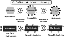
From these results, possible phenomenon with electrolysis oxidation can be summarized in Fig. 7. Both untreated chalcopyrite and molybdenite are hydrophobic. With electrolysis oxidation, chalcopyrite became hydrophilic since hydrophilic iron sulfate and iron oxyhydroxide covered on the surface. With retention in electrolyte after electrolysis, iron sulfate dissolved and replaced with iron oxyhydroxide because of re-precipitation then surface keep hydrophilic. On the other hand for molybdenite, with electrolysis oxidation, molybdenum oxide produced but surface keep weak hydrophobic since molybdenum oxide is soluble. With retention in electrolyte after electrolysis, surface keep weak hydrophobic since still small amount of molybdenum oxide stayed on the surface.
3.4 Comparison of oxidation treatment method
Electrolysis oxidation was achieved in this work. The authors performed plasma and ozone oxidation treatments in previous work7,8). The results of these oxidation treatments are shown in Table 1, which compares the contact angles measured on untreated and treated chalcopyrite and molybdenite surface electrodes. The following treatments were performed: 800-s electrolysis at 1.2 V, 30-min ozone treatment, 1-min plasma treatment, and 120 min of washing after the plasma treatment. The data corresponding to the plasma and ozone treatment were taken from a previous paper7,8) and oxidation procedure and condition is as follows. For ozone oxidation, massive mineral sample was suspended in 10−3 M KCl at pH 9 then dispersed with ultrasonic for 1 min followed by stirred at 700 rpm with bubbling ozone for 30 min. Ozone was produced from 2 L min−1 pure oxygen and ozone generation rate was about 2.4 g h−1. Ozone concentration in this gas is 20 g m−3. For plasma treatment, plasma treatment was carried out for massive mineral sample with plasma generator (Model PA 1504, Kyoto Denshi-Keisoku Co., Ltd.) at 10 W for 10 min by oxygen plasma at 100 Pa using a frequency of 13.56 MHz. After plasma treatment, sample washing was achieved as following procedure: plasma treated massive sample was suspended in a beaker with a solution of pH 9 adjusted with potassium hydroxide (hereafter; pH 9 solution) and magnetic stirred with bubbling oxygen for sample washing for 120 min. The difference in the contact angle before and after oxidation in brackets in table. Also the difference in the contact angle between chalcopyrite and molybdenite is shown. As the table shows, high contact angles occur for both the untreated chalcopyrite and molybdenite. The contact angles differ only slightly and are therefore difficult to distinguish via flotation. However, the contact angles of the plasma-treated surfaces are considerably lower than those of the untreated surfaces. After washing, the contact angle of molybdenite recovered, but the contact angle of chalcopyrite was still lower than that of the untreated surface. The contact angle of both electrodes decreased with electrolysis and ozone oxidation, and the contact angle of oxidized chalcopyrite is lower than that of molybdenite. More importantly, the difference in the contact angles of the treated electrodes indicates that different floatability can be achieved with these treatments.
Table 1
Contact angle (degrees, °) of the chalcopyrite and molybdenite oxidized via various oxidation methods.
| |
Untreated |
Electrolysis at 1.2 V |
Ozone for 30 min |
Plasma treated |
Washed for 120 min after Plasma |
| Chalcopyrite |
71.7 |
42.4 (29.3) |
30.2 (41.5) |
26.0 (45.7) |
63.1 (8.6) |
| Molybdenite |
68.6 |
67.0 (1.6) |
40.8 (27.8) |
25.1 (43.5) |
81.8 (13.2) |
| Difference |
3.1 |
24.6 |
10.6 |
0.9 |
18.7 |
These results suggested following phenomenon: for untreated chalcopyrite and molybdenite, contact angle are high because of both hydrophobic property. After plasma treatment, both chalcopyrite and molybdenite contact angle became low since both were covered with hydrophilic oxidation products on the surface. Followed by water washing makes only molybdenite contact angle recovered since molybdenite oxide dissolution. with ozone oxidation treatment, both chalcopyrite and molybdenite contact angle became low since ozone is strong oxidants then both are oxidized. But molybdenite contact angle is higher than that of chalcopyrite since dissolution of molybdenite oxide. With electrolysis oxidation, it seems similar with ozone treatment but contact angle difference between chalcopyrite and molybdenite is higher than that of ozone treatment. It seems that chalcopyrite oxidation is preference more than molybdenite because of its resistivity difference.
The XPS results suggest that the surface of molybdenite is oxidized during plasma and ozone oxidation, i.e., oxygen is attached to the surface of the molybdenite layer. With washing after plasma treatment, molybdenum oxide is dissolved, probably as oxide ions such as MoO42−, as indicated by the pH-Eh diagram8,9). As a result, the surface of molybdenite is preserved with washing.
These results indicate that oxyhydroxide and molybdenite oxide are deposited, through various oxidation methods, on the surface of chalcopyrite and molybdenite, respectively. A comparison of the XPS results and the oxide-coverage product on the surface of chalcopyrite revealed that greater levels of oxidation occur during ozone and electrolysis treatments than during plasma oxidation. In contrast, compared with ozone and electrolysis, the plasma treatment yields greater oxide-product coverage of the molybdenite surface. In other words, although plasma oxidation is weaker than ozone and electrolysis oxidation, molybdenum oxide persists on the surface of plasma-treated molybdenite because this oxidation is performed under dry conditions. Because molybdenum oxide is soluble in water, subsequent washing resulted in a decrease in the amount of molybdenum oxide on the surface. Ozone and electrolysis oxidation strongly oxidize chalcopyrite and molybdenite and depress flotation on both surfaces. Applying electrolysis oxidation to powder samples is difficult and improvements are required to realize selective flotation. Plasma oxidation is considered complex, because dry conditions are required for plasma application. The ozone treatment is applicable to selective flotation, but excessive oxidation ability and high cost hinder the realization of selective flotation. The knowledge provided by this work may be useful in developing new and efficient oxidation techniques for achieving selective flotation.