Abstract
A dismantling process for separating electric and electronic components (EECs) from printed circuit board (PCB) was developed by using hydrochloric acid (HCl) leaching with stannic ions (Sn4+). The use of HCl solution with Sn4+ ions dissolves tin (Sn)-alloy solder that holds EECs on bare board, which allows the EECs to be detached from PCB. The feasibility of the new dismantling process was investigated by examining the effects of temperature, initial Sn4+ concentration and agitation speed on the dismantling of PCB. The effect of agitation speed was negligible and the dismantling-completion time was reduced rapidly with increasing temperature and initial Sn4+ concentration. The dismantling of PCB was completed within 30 min under the leaching conditions; HCl concentration, 1 mol/L; initial Sn4+ concentration, 13,000 mg/L; temperature, 90℃; and agitation speed, 300 rpm. Each metal was enriched after dismantling process; e.g. the content of Ag increased from 0.016% in PCB to 3.118% in registor. It was expected that efficient PCB recycling process could be designed to recover metals from EECs with higher concentrated metals.
1. Introduction
A printed circuit board (PCB) is a fundamental part of electrical equipment and consists of a bare board and various kinds of electric/electronic components (EECs) such as integrated circuits (IC), relays, resistors, and capacitors1,2). Generally, it has been known that PCB contains about 40% of metallic materials, 30% of organic resin materials, and 30% of glass materials used as resin reinforcing fibers3,4). Among the various kinds of nonmetallic components, bromine flame retardant is especially considered as a major toxic material which can cause crucial environmental problems and damage the human body due to the generation of dioxin or furan when incinerated5–8). The metallic components consist of valuable but harmful metals such as Au, Ag, Pd, Ni, Cu, Al, Pb, Cd and Sn9), so improper discharge of PCBs could not only cause the loss of valuable resources but also result in serious contamination of air, soil, and streams3,10). Therefore, pyrometallurgical and hydrometallurgical PCB recycling processes have been developed for recovering valuable metals as well as for preventing any potential environmental problems caused by PCB waste.
Recycling processes have employed hydrometallurgical ways due to no gas emission and lower capital costs11,12). The hydrometallurgical recycling processes require liberation processes such as comminution to facilitate contact between leach solution and metal components from PCB prior to hydrometallurgical processes13), but the loss of precious metals such as gold, silver, and palladium during extensive comminution was reported in the conventional processes14). Even though the amount of precious metals in PCB is less than 1%, they account for more than 80% of the total intrinsic values, as shown in Table 115), which means that the loss of precious metals during conventional recycling processes reduces the economic feasibility of PCB recycling.
Table 1
Compositions and the intrinsic values of metals in PCB.
| Component |
Wt.%10) |
Valuea ($/kg) |
| Gold |
0.025 |
44201.06 |
| Palladium |
0.010 |
22574.96 |
| Silver |
0.100 |
613.40 |
| Copper |
16.0 |
4.67 |
| Aluminium |
5.0 |
1.69 |
| Iron |
5.0 |
0.33 |
| Tin |
3.0 |
19.58 |
| Lead |
2.0 |
1.99 |
| Nickel |
1.0 |
1.04 |
| Zinc |
1.0 |
2.23 |
aMetal values are based on October 2016 London Metal Exchange (LME) levels.
PCB dismantling process, where bare board and each EEC could be separated, has been recognized as an alternative recycling technology. The precious metals could be enriched by the dismantling processes since each EEC contains different precious metals16,17). Therefore, the EEC containing precious metals could be selectively treated by suitable hydrometallurgical methods; and therefore, it is expected to make the recycling processes more efficient and simpler12). Studies on the dismantling have attempted to remove the solder, which joins EECs on bare board, by thermal18–20) or mechanical processes21). Various heating sources have been employed to melt the solder components such as industrial waste heat18) and infrared heating19,20). Lee at al.21) have shown PCB dismantling with automatic mechanical dismantling apparatus by employing diamond grinders. Because these thermal and mechanical separation processes have disadvantages such as consumption of high energy and loss of solder components, respectively, chemical dissolution processes have been investigated as an alternative method using a water-soluble ionic liquid22), methanesulfonic acid with hydrogen peroxide23), and fluoroboric acid with hydrogen peroxide24). However, the high cost of ionic liquid and the instability of hydrogen peroxide are significant drawbacks that hinder their use in commercial plants25,26). Nitric acid could also be considered in terms of leaching Sn9,27), but it is unsuitable for use as a strong oxidizing power to dissolve copper and silver and to generate NOx gas.
In the present study, a new PCB dismantling process was developed by employing HCl leaching with stannic chloride. It is expected that Sn4+ ions play a role as an oxidant to accelerate the dissolution of the tin-alloy solder. The effects of temperature, initial Sn4+ concentration and agitation speed on the PCB dismantling process were investigated to establish the recycling process. Finally, enrichment of metal components was evaluated by comparing the metallic contents in PCB and dismantled parts.
2. Experimental Procedure
Waste memory-typed PCBs were collected from a recycling company in Korea. The width and height of the PCB are 50 mm and 160 mm, respectively, and it contains around 250 parts of EECs such as IC chips, capacitors, and resistors. The contents of metal in the PCB are given in Table 2. All reagents used in this study were of reagent grade.
Table 2
The results of ICP analysis on the content of major elements in the PCB.
| Elements |
Cu |
Fe |
Ni |
Sn |
Pb |
Ag |
Au |
| Contents (%) |
17.1 |
2.8 |
2.4 |
2.2 |
0.8 |
0.0162 |
0.0967 |
As illustrated in Fig. 1, dismantling tests of the PCB were conducted in a water-jacketed reactor, which was connected to a heating bath circulator, to maintain temperature of leach solution. The reactor was capped with silicone stopper, equipped with reflux condenser to prevent evaporation of the solution. A PCB sample, cut in two pieces, was hung with a thread to guarantee contacting between both sides of PCB and leach solution because all components are mounted on both sides of the board by surface mounted device technology. The concentration of HCl and Sn4+ in leach solution were adjusted to 1 mol/L and 7,000 to 13,000 mg/L, respectively. The weight of PCB and the volume of leach solution were 41.1 g (one PCB sample) and 550 ml, respectively. An agitation speed was set at 100 rpm to 300 rpm with a magnetic stirrer.

During the tests, EECs parts detached from PCB were removed from the solution and the number of parts were counted to calculate dismantling ratio, which was calculated as the following equation.
| \[{\rm Dismantling}\ {\rm ratio}\ (\%) = \frac{{\rm N}_{\rm c}}{{\rm N}_{\rm t}} \times 100\] | (1) |
where Nc indicates the number of EECs detached from the PCB and Nt is the whole number of EECs on the PCB. At designated time, 2 cm
3 of the solution was withdrawn and filtered with 0.45 µm membrane filter. After diluting the filtrate with HNO
3 for Pb, Cu, Ni, and Fe and HCl for Sn, the solution was analyzed using inductively coupled plasma-optical emission spectrometry (ICP-OES, OPTIMA 8300, PerkinElmer Inc., USA).
Finally, disassembled components were sorted manually into IC, registor, and capacitor. Each group of component was ground with a mixer mill (MM400, Retsch GmbH & Co, Germany), while bare board was shredded with a cutting mill (SM100, Retsch GmbH & Co, Germany) followed by being ground with the mixer mill. The metal contents of ground products were measured with ICP-OES after chemical digestion.
3. Results and Discussions
During the tests, EECs parts detached from PCB were removed from the solution and the number of parts were counted to calculate dismantling ratio, which was calculated as the following equation.
Metallic solder consists of mainly tin alloy combined with lead, copper, bismuth, zinc, indium, antimony and silver26,28,29). Kim et al.29) reported that Sn4+ ions can oxidize tin metal in chloride solution and make two stannous (Sn2+) ions as given in eq. (2).
| \[{\rm Sn}^{4+} + {\rm Sn} = 2{\rm Sn}^{2+}\] | (2) |
where the standard electrode potential of Sn
4+/Sn
2+ couple was reported to be 0.151 V
30) and 0.384 V
31), which indicates the reaction in eq. (1) is spontaneous. Furthermore, since the standard electrode potentials of Ag and Cu are 0.80 V and 0.34 V, respectively
32), the selective dissolution of Sn could be expected, which enables EECs detachment while suppressing dissolution of Ag or Cu.
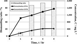
Dismantling tests were performed to examine the detachment of EECs by dissolving solder in 1 mol/L HCl solution with 10,000 mg/L Sn4+ at 50℃ and 300 rpm. Figure 2 shows the concentrations of tin and lead and the dismantling ratio of EECs, where EECs began to be detached from the board within 1 hour and the concentration of tin increased to more than 1,000 mg/L. When the dismantling was completed within 4 hours, the concentration of tin and lead were 1,550 mg/L and 432 mg/L, respectively. These results indicate that the dissolution of solder play an important role in the detachment of EECs. Figure 3 shows the photo of PCB before dismantling test (Fig. 3(a)) and bare board (Fig. 3(b)) and EECs (Fig. 3(c)) after the test, which shows the dismantling of PCB was achieved successfully.
The leaching behavior of Cu, Ni, and Fe were also investigated, and results were shown in Fig. 4. The concentrations of Cu, Ni, Fe increased gradually to 163 mg/L, 64 mg/L, 26 mg/L, respectively, within 4 hours. Although Cu is not oxidized by Sn4+ as discussed above, Cu could dissolve by forming complex ion with Cl−33,34). The lower concentrations of Cu, Ni, and Fe than those of Sn and Pb would result from the fact that Cu, Ni, and Fe were not exposed to the leach solution, and that Sn4+ has a mild oxidizing power.

The effects of agitation speeds on the dismantling of EECs were investigated in 1 mol/L HCl solution with 10,000 mg/L Sn4+ at 100 to 300 rpm and 50℃. The results presented in Fig. 5 indicate that the effect of agitation speed on the detachment time is negligible in this agitation-speed range. Therefore, agitation speed of 300 rpm was selected in all the subsequent dismantling processes. Controlling temperature is one of most effective ways to accelerate the chemical reaction. The effect of temperature on the dismantling process were investigated in 1 mol/L HCl with 10,000 mg/L Sn4+ at 300 rpm and 30–90℃. As shown in Fig. 6, the EECs dismantling time decreased rapidly with increasing temperature. All EECs were detached from the PCB within 7 hours at 30℃ but it was achieved within 45 minutes at 90℃ with 10,000 mg/L Sn4+.


In this study, Sn4+ ions act as an oxidant to oxidize Sn metal of the solder. The effect of initial Sn4+ concentration was investigated in 1 mol/L HCl with 7,000 to 13,000 mg/L at 50℃ and 300 rpm. When the detachment of EECs was completed, the concentration of tin increased to around 1,500 mg/L. The initial concentration of added tin was adjusted to 7,000 to 10,000 mg/L which are more 4~8 times than the required stoichiometric concentration. As shown in Fig. 7, dismantling time decreased with increasing the initial concentration of Sn4+. The dismantling time of EECs decreased from 5 hours with 7,000 mg/L Sn4+ to 2 hours with 13,000 mg/L. Consequently, the result showed that increasing the concentration of oxidants can accelerate the dissolution of tin solder. Moreover, it was found that adding Sn4+ more than stoichiometric ratio has noticeable effects on accelerating the reaction.

Figure 8 shows the effects of initial concentration of Sn4+ and temperature simultaneously on the dismantling-completion time, where the concentration of HCl and agitation speed were fixed at 1 mol/L and 300 rpm, respectively. The results show that the dismantling-completion time decreased from 8 hours to 30 minutes with increasing temperature and concentration from 30℃ and 7000 mg/L to 90℃ and 13000 mg/L.

The metal contents of EEC after dismantling test were summarized in Table 3. Each metal was concentrated in each EEC; Au in IC, Ag in resistor, Cu in bare board, Ni in IC and Capacitor, and Fe in IC. Especially, the content of Ag was about 200 times more than in resistor than in PCB. Furthermore, some metal species were not detected; e.g. Sn and Pb are not in bare board, and capacitor contains only Cu, Ni, Fe, Ag and Ti, not Au, Sn and Pb. These results indicate that more efficient metallurgical processes could be designed to recover metals from each EEC, which could improve the economic efficiency of the PCB recycling processes.
Table 3
Metal composition of each component after dismantling test (%).
| Elements |
PCB |
Bare board |
IC |
Resistor |
Capacitor** |
| Au |
0.096 |
0.048 |
0.164 |
nd* |
nd* |
| Ag |
0.016 |
0.012 |
0.085 |
3.118 |
0.599 |
| Cu |
17.5 |
31.7 |
2.9 |
nd* |
2.9 |
| Ni |
2.9 |
0.5 |
7.5 |
1.2 |
14.8 |
| Fe |
2.9 |
0.1 |
11.0 |
0.7 |
0.1 |
| Sn |
1.5 |
nd* |
0.4 |
0.4 |
nd* |
| Pb |
1.3 |
nd* |
0.9 |
0.4 |
nd* |
* nd: not detected
** The capacitor is found to contain 15.4% of Ti.
4. Conclusion
A dismantling process of PCB was investigated as a pretreatment method for PCB recycling to reduce the loss of precious metals, and leaching process using HCl solution with Sn4+ ions was used to achieve the dismantling of EECs from PCB by dissolving Sn-alloy solder.
The effects of agitation speed on PCB dismantling test was negligible in a range of 100 to 300 rpm, while the dismantling-completion time decreased rapidly with increasing temperature and the initial concentration of Sn4+. The dismantling of EECs from PCB was completed within 30 min under the leaching conditions; HCl concentration, 1 mol/L; initial Sn4+ concentration, 13,000 mg/L; temperature 90℃; and agitation speed, 300 rpm. The contents of metal were investigated in PCB (before dismantling) and each EEC (after dismantling), and each metal was concentrated significantly in each EEC; e.g. the content of Ag increased from 0.016% in PCB to 3.118% in registor. These results indicate that the dismantling process could contribute the enhancement of metal-recovery efficiency in subsequent metallurgical processes.
Acknowledgments
This study was supported by the National Research Foundation of Korea (NRF) grant funded by the Korea government (MSIP) (No. 2017R1A2B1008174).
REFERENCES
- 1) J. Guo, R. Zhang and Z. Xu: Environ. Sci. Technol. 49 (2015) 2716–2723. 10.1021/es5053599
- 2) P. Zhu, Y. Chen, L.Y. Wang, M. Zhou and J. Zhou: Waste Manag. 33 (2013) 484–488. 10.1016/j.wasman.2012.10.003
- 3) H. Duan, K. Hou, J. Li and X. Zhu: J. Environ. Manage. 92 (2011) 392–399. 10.1016/j.jenvman.2010.10.057
- 4) T. Hino, R. Agawa, Y. Moriya, M. Nishida, Y. Tsugita and T. Araki: J. Mater. Cycles Waste 11 (2009) 42–54. 10.1007/s10163-008-0218-0
- 5) J.B. Legarth: Resour. Conserv. Recycling 19 (1997) 109–135. 10.1016/S0921-3449(96)01186-X
- 6) X.H. Bi, B. Simoneit, Z.Z. Wang, X.M. Wang, G.Y. Sheng and J.M. Fu: Atmos. Environ. 44 (2010) 4440–4445. 10.1016/j.atmosenv.2010.07.040
- 7) H. Li, L. Yu, G. Sheng, J. Fu and P. Peng: Environ. Sci. Technol. 41 (2007) 5641–5646. 10.1021/es0702925
- 8) X.H. Bi, G. Thomas, K. Jones, W.Y. Qu, G.Y. Sheng, F. Martin and J.M. Fu: Environ. Sci. Technol. 41 (2007) 5647–5653. 10.1021/es070346a
- 9) S. Jeon, I. Park, K. Yoo and H. Ryu: Geosystem Eng. 18 (2015) 213–218. 10.1080/12269328.2015.1048836
- 10) M. Habib, Q. Sohaib, A. Ullah, U. Habib and A. Khan: Particul. Sci. Technol. 34 (2016) 301–307. 10.1080/02726351.2015.1075638
- 11) E. Bae and K. Yoo: Geosystem Eng. 19 (2016) 312–316. 10.1080/12269328.2016.1247754
- 12) J.M. Yoo, J. Jeong, K. Yoo, J.C. Lee and W. Kim: Waste Manag. 29 (2009) 1132–1137. 10.1016/j.wasman.2008.06.035
- 13) J. Cui and L. Zhang: J. Hazard. Mater. 158 (2008) 228–256. 10.1016/j.jhazmat.2008.02.001
- 14) P. Chancerel, C.E.M. Mesker, C. Hagelüken and V.S. Rotter: J. Ind. Ecol. 13 (2009) 791–810. 10.1111/j.1530-9290.2009.00171.x
- 15) Y.J. Park and D.J. Fray: J. Hazard. Mater. 164 (2009) 1152–1158. 10.1016/j.jhazmat.2008.09.043
- 16) Y. Kim, J. Lee, J.C. Lee and J. Lee: J. Korean Soc. Geosystem Eng. 49 (2012) 728–735.
- 17) P. Mońka, W. Szczepaniak and M. Zabłocka-Malicka: Czasopismo Techniczne z. 1-Ch (2011) 119–126.
- 18) M. Chen, J. Wang, H. Chen, O.A. Ogunseitan, M. Zhang, H. Zang and J. Hu: Environ. Sci. Technol. 47 (2013) 12409–12416. 10.1021/es402102t
- 19) S. Park, S. Kim, Y. Han and J. Park: Int. J. Miner. Process. 144 (2015) 11–15. 10.1016/j.minpro.2015.09.013
- 20) S. Yokoyama and M. Iji: Proc. IEEE Int. Symp. Electronics and the Environment (San Francisco, California, 1997) pp. 109–114.
- 21) J. Lee, Y. Kim and J.C. Lee: J. Hazard. Mater. 241–242 (2012) 387–394. 10.1016/j.jhazmat.2012.09.053
- 22) X. Zheng, J. Li, H. Xie and L. Liu: Chemosphere 93 (2013) 1288–1294. 10.1016/j.chemosphere.2013.06.063
- 23) X. Zhang, J. Guan, Y. Guo, Y. Cao, J. Guo, H. Yan, R. Su, B. Liang, G. Gao, Y. Zhou, J. Xu and Z. Guo: Environ. Prog. Sustain. Energy (2017). 10.1002/ep.12527
- 24) X. Zhang, J. Guan, Y. Guo, X. Yan, H. Yuan, J. Xu, J. Guo, Y. Zhou, R. Su and Z. Guo: ACS Sustain. Chem. & Eng. 3 (2015) 1696–1700. 10.1021/acssuschemeng.5b00136
- 25) H. Cui and C.G. Anderson: J. Adv. Chem. Eng. 6 (2016) 142–153. 10.4172/2090-4568.1000142
- 26) S.H. Lee, K. Yoo, M.K. Jha and J.C. Lee: Hydrometallurgy 157 (2015) 184–187. 10.1016/j.hydromet.2015.08.016
- 27) K. Yoo, J.C. Lee, K. Lee, B. Kim, M. Kim, S. Kim and B.D. Pandey: Mater. Trans. 53 (2012) 2175–2180. 10.2320/matertrans.M2012268
- 28) S. Kim, J.C. Lee, K.S. Lee, K. Yoo and R.D. Alorro: Mater. Trans. 55 (2014) 1885–1889. 10.2320/matertrans.M2014289
- 29) S.K. Kim, J.C. Lee and K. Yoo: Hydrometallurgy 165 (2015) 142–147.
- 30) M. Pourbaix: Atlas of electrochemical equilibria in aqueous solutions, NACE (National Association of Corrosion Engineers) International, Houston, (1974) p. 476.
- 31) T. Gajda, P. Sipos and H. Gamsjäger: Monatsh. Chem. 140 (2009) 1293–1303. 10.1007/s00706-009-0188-5
- 32) C.M.A. Brett and A.M.O. Brett: Electrochemistry, (Oxford University Press Inc., New York, 1993) pp. 416–419.
- 33) H.K. Lin, X.J. Wu and P.D. Rao: JOM 43 (1991) 60–65. 10.1007/BF03221107
- 34) K. Yoo, S.K. Kim, J.C. Lee, M. Ito, M. Tsunekawa and N. Hiroyoshi: Miner. Eng. 23 (2010) 471–477. 10.1016/j.mineng.2009.11.007
