Lifetime in Steel Cord Wire Drawing Dies of WC–Co Cemented Carbide Containing TaNbC or Cr3C2
2018 Volume 59 Issue 5 Pages 754-759
Details
2018 Volume 59 Issue 5 Pages 754-759
Wire-drawing dies and specimens of WC–Co cemented carbides containing TaNbC or Cr3C2 were fabricated by hot isostatic pressing (HIP) at 1633 K in 40 MPa Ar and by annealing at 1593 K in vacuum. The lifetimes of steel cord wire-drawing dies were evaluated and their mechanical properties such as hardness, transverse rupture strength, and fracture toughness were examined. The lifetime of the drawing die was noted to have remarkably improved by annealing for WC–Co cemented carbides containing both TaNbC and Cr3C2. The alloys containing TaNbC had longer lifetimes than those containing Cr3C2. The lifetime of a drawing die was weakly related to its hardness but appeared to have no correlation with its strength or toughness. The remarkable improvement in the drawing die lifetime resulting from annealing treatment after HIP and the longer lifetime of TaNbC-containing alloys can be understood in terms of the adhesion strength between the WC and Co phases being affected by the alloy content and heat treatment of cemented carbides.
This Paper was Originally Published in Japanese in J. Jpn. Soc. Powder Powder Metallurgy 64 (2017) 17–22.
Tungsten carbide–cobalt (WC–Co) cemented carbide has been widely used as steel cord wire-drawing dies to strengthen automotive tires. The authors have described the wear of WC-based cemented carbide dies for steel cord wire drawings in a previous paper.1) Drawing dies of WC–Co cemented carbides containing added TaNbC, Cr3C2, and VC and Ni as a binder phase instead of Co were fabricated and their lifetimes as steel cord wire drawings were investigated. The WC–Co cemented carbide with added TaNbC was found to exhibit the best wire-drawing lifetime, followed by Cr3C2 containing cemented carbide, and the VC containing alloy and Ni binder phase alloy were found to exhibit shorter lifetimes. The wear mechanism of the cemented carbide used for wire drawing of a steel cord is discussed, considering the relationships between wire-drawing lifetime, microstructure, and properties of alloys. When the authors considered the wear mechanism of wire-drawing dies, they argued that the wear mechanism of WC particles that were maintained by the Co binder phase was dominant, and they also believed that the refinement of WC particles without degradation of adhesion at the WC/Co interface was the most important material design principle. In the previous report,1) the effects of composition and WC grain size were studied under unified conditions for a synthetic process in which hot isostatic pressing (HIP) was performed after liquid-phase sintering. However, HIP is not always necessarily an optimum synthetic process in terms of the wire-drawing die lifetimes. Therefore, to clarify the material design principle for improving the lifetime of dies, evaluating this consideration, including the effects of the composition and WC grain size, is essential.
In this study, notably, WC–Co cemented carbide with added TaNbC or Cr3C2, which had a longer wire-drawing lifetime, formed alloys (materials) with different WC grain sizes after liquid-phase sintering and resintering (annealing) following HIP. The steel cord wire-drawing lifetime, microstructure, and material properties (hardness, transverse rupture strength, and fracture toughness) of these alloys were examined in detail. Moreover, the material design principles of cemented carbide dies for steel cord wire drawings were analyzed from the viewpoint of their microstructure and synthetic process.
Commercial WC powders (mean particle size 1.0–2.0 µm, Japan New Metals), Ta0.8Nb0.2C (1.0 µm, Japan New Metals), Cr3C2 (1.5 µm, H.C. Starck), and Co (1.2 µm, Umicore) were used as raw materials. These powders were mixed in an attritor (time: 28.8 ks), dried, pressed, and sintered. Sintering was performed under vacuum at 1653–1723 K for 3.6 ks, and HIP was performed in Ar at 40 MPa and 1633 K for 3.6 ks to eliminate the influence of residual pores after sintering. In this study, the specimen was heat-treated again at 1593 K for 3.6 ks in vacuum after HIP. This treatment could be described as “resintering” because the sample was heated to the liquid-phase appearance temperature2) (approx. 1573 K). However, since this treatment can be adequately called “annealing” considering the microstructural changes described later, it is hereafter referred to as “annealing treatment”, and an annealed sample is hereafter referred to as an “annealed alloy”.
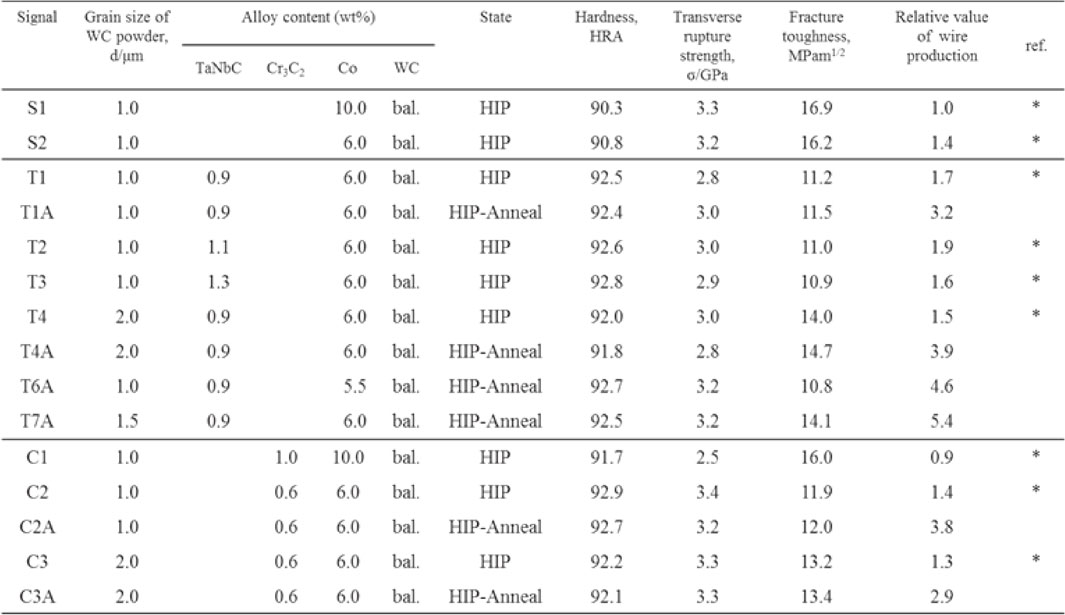
Table 1 shows the material compositions of the cemented carbide samples fabricated in this study (their material properties are described later). WC–Co cemented carbide without additive (straight) is designated S alloy, and the cemented carbide with added TaNbC or Cr3C2 is designated T or C alloy, respectively. WC powder with a grain size of 1 µm was mainly used, in addition to WC powder with a coarse grain size of 1.5–2.0 µm. In the table, the samples described in the previous report1) are marked with “*” in the reference column (ref.). The samples were firstly observed via SEM, and then a Rockwell hardness (HRA) test was performed. The samples for testing transverse rupture strength had sizes of 4 × 8 × 25 mm, and a three-point bending test (span 20 mm) was performed. The fracture toughness was obtained by the IF method with a load of 10 kgf, using Niihara’s equation3) for Palmqvist type cracks.
The experimental method for wire drawing was the same as that described in our previous report.1) The steel cord material was 0.82% C with a brass coating on its surface, and the starting wire diameter was 1.17 mm. The wire was drawn 21 times (the number of dies), the final wire diameter was 0.220 mm, and the wire-drawing speed during the final stage was 800 m/min. All dies used were immersed in lubricating liquid. The wet type lubricating liquid was an emulsion containing an extreme pressure agent, a deforming agent, and antiseptics. The cemented carbide shown in Table 1 was used in the last three dies of the 21 dies used for the wire-drawing experiment. Other dies were cemented carbide dies that were used for normal production. When the above three dies for these studies reached the end of their lifetime, all dies were replaced with new ones. To evaluate the wire-drawing lifetime, the wire diameter was measured using a micrometer after wire drawing, and the dies were judged to reach the end of their lifetimes when the wire diameter became 0.225 mm. The average amount of wire drawn (kg) was obtained for wire drawing n times, where n = 3–5, and the lifetime was evaluated as the relative amount of wire drawn. The relative amount of wire drawn was obtained by dividing the average amount of wire drawn for each cemented carbide by that drawn with Material S1, which is the base cemented carbide.
To examine gas contained in the HIP-treated and annealed specimens, a bending test was performed in an ultra-high vacuum of approximately 10−9 Pa, and the gas released was analyzed using a mass spectrometer.4)
Figure 1 shows the SEM microstructures of nine main samples of T and C alloys. Firstly, a comparison of T4 and T1 revealed that the WC grain size in the alloys decreases with the size of WC powder used. A comparison of T1 and T1A, T4 and T4A, and C2 and C2A revealed that annealing treatment slightly increased the WC grain size. As for the T and C alloys, almost no difference existed in the WC grain size when the same WC powder size was used. We observed that T and C alloys had smaller WC grain sizes than the S alloy (photos omitted).
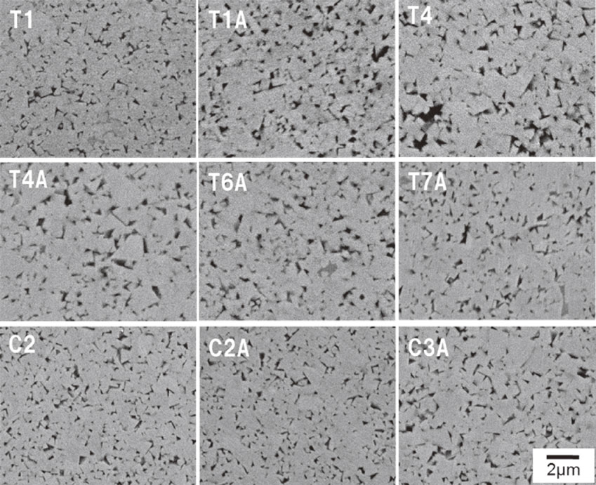
SEM microstructures of cemented carbide specimens.
The hardness, transverse rupture strength, and fracture toughness of the T, C, and S alloys were examined as shown in Table 1. The hardness of the T alloy is higher than that of the S alloy. The hardness tended to decrease as the WC grain size increased, and it increased as the Co content decreased. The hardness tended to decrease to some extent after annealing treatment. The transverse rupture strength of the T alloy tended to be equal to or slightly inferior to that of the S alloy. The fracture toughness of the T alloy was lower than that of the S alloy. The fracture toughness increased with an increase of WC grain size and decreased with a decrease of Co content. A comparison of HIP-treated and annealed alloys in an identical sample revealed that the fracture toughness was higher in annealed alloys. The fracture toughness was reduced in T1 and T1A.
The C alloy was harder than the S alloy, and the hardness tended to decrease as the WC grain size increased and also tended to decrease slightly after annealing. The C alloy was harder than the T alloy for the same grain size, Co content, and sintering conditions. The C alloy had the same transverse rupture strength as the S alloy and a lower fracture toughness than the S alloy. The fracture toughness increased with the WC grain size. Compared with the T alloy, there was no significant difference in fracture toughness for the same hardness. However, the fracture toughness was higher for both cemented carbides than for T1 and T1A.
The wire-drawing results are shown in Fig. 2 and Table 1. The relative amounts of wire drawn (lifetime) with S1 denoted as 1 are shown. The bar chart in Fig. 2 shows the mean and relative value of wire-drawing lifetimes. White and black bars indicate HIP-treated and annealed alloys, respectively. Here, the important result is that annealed alloys had significantly longer wire-drawing lifetimes than HIP-treated alloys. For the annealed alloys, the wire-drawing lifetime decreased in the order T7A > T6A > T4A > C2A, and T7A was the most superior. The wire-drawing lifetime of the C alloy varied widely, from 0.41 to 6.22 (n = 5) for C2A with an average of 3.8. In many cases, the C alloy had a smaller wire-drawing lifetime that was below 1. As shown above, alloys with wire-drawing lifetimes below 1 are considered to be impractical from the viewpoint of die replacement. The T1A alloy, which had the smallest wire-drawing lifetime among the annealed T alloys with 6% Co, exhibited wire-drawing lifetimes from 2.1 to 4.7 (n = 5) with an average of 3.2. The T7A alloy, which had the longest wire-drawing lifetime among the 6% Co alloys, showed a wire-drawing lifetime that approximately varied from 3.2 to 9.1 (n = 5) with an average of 5.4. These T alloys are considered suitable for die replacement and management because of their larger wire-drawing lifetime than C alloys.
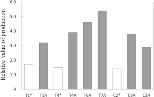
Relative value of wire production.
Figure 3 shows plots of the wire-drawing lifetime as a function of hardness. Here, the white and black points indicate HIP-treated and annealed alloys, respectively. Points for the annealed alloys are plotted in the upper area. Overall, a longer wire-drawing lifetime is obtained for a higher hardness (HRA92.0–93.0), although the wire-drawing lifetime varies even for the same hardness. Abrasion is considered to progress more easily with lower hardness, and as described in the previous report,1) macroscopic abrasion (chipping of material) occurs more easily when the hardness is extremely high, which shortens the wire-drawing lifetime.

Relative value of wire production for each die (specimen) as a function of hardness.
Figure 4 depicts plots of the wire-drawing lifetime as a function of the transverse rupture strength. In this case, we also found that the points for the annealed alloys were plotted in the upper area. The wire-drawing lifetime appears to peak at a strength of around 3.2 GPa. However, overall a strong correlation does not appear between wire-drawing lifetime and strength.
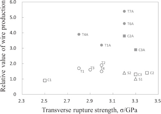
Relative value of wire production for each die (specimen) as a function of the TRS.
Figure 5 shows plots of the wire-drawing lifetime as a function of fracture toughness. We found that some alloys showed a poor wire-drawing lifetime in spite of a high fracture toughness. Compared with hardness and strength, the correlation between fracture toughness and the wire-drawing lifetime is the lowest.
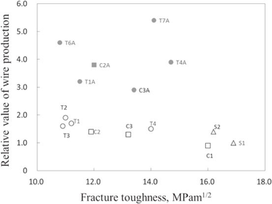
Relative value of wire production for each die (specimen) as a function of fracture toughness.
Figure 6 shows the analysis results for the gas that was emitted during the bending test under ultra-high vacuum for T1 and T1A. Various gases were detected, which differed only slightly between T1 and T1A, except for Ar. With the exception of Ar, these gases are considered to have been generated by friction between the test piece surface and jig as well as to have been emitted inside the test piece during the bending test. Regarding Ar, an electric current of approximately 10 × E−10 A was detected from the HIP-treated alloy, though this decreased to one third of its original value in the annealed alloy. This is an important result, which indicates that Ar permeates in cemented carbides during HIP and is removed by annealing treatment after HIP.
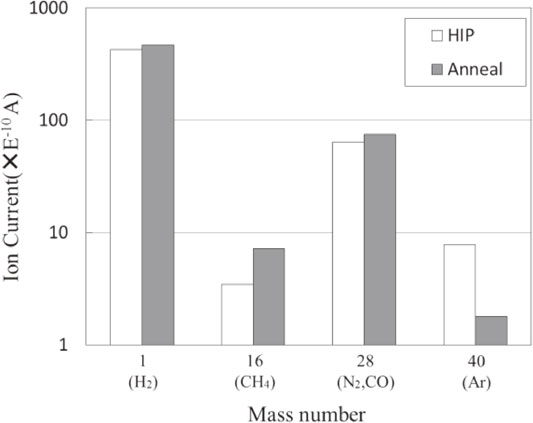
Gas released from the material during the bending test under ultra-high vacuum. The test was performed on T1 and T1A.
Fifteen types of cemented carbide dies were fabricated from T alloy with TaNbC, C alloy with Cr3C2, and S alloy without additive, including samples that were treated with HIP and those that were annealed after HIP, and their steel cord wire-drawing lifetimes were evaluated. The most important result obtained in this study is that the wire-drawing lifetime drastically improved after annealing following HIP. It is also important that the T alloy had a longer wire-drawing lifetime than the C alloy.
In our previous report,1) we proposed two wear mechanisms for cemented carbide wire-drawing dies, which were microscopic and macroscopic wear. They argued that microscopic wear was the dominant mechanism for steel cord wire-drawing dies, and that the interface strength (similar to adhesive strength) of WC/Co and the holding power of the Co phase with respect to WC grains were important factors for wear mechanisms. Moreover, the effects of microstructural properties of cemented carbides, such as WC grain size or additives, were considered as follows.
The reason why wire drawing lifetime was better with smaller WC grain sizes was because the holding power by the Co phase of WC grain became stronger. The effect of additives for WC grain growth inhibitor on wire drawing lifetime was that TaNbC-added cemented carbide was the most superior in the order of VC < Cr3C2 < TaNbC. The reason for this was considered to be that these additives, which dissolved in the Co liquid phase during sintering, were precipitated at the WC/Co boundary surface during cooling with degrees of precipitation in the order VC > Cr3C2 > TaNbC.
Firstly, more quantitative arguments will be presented for precipitation at the WC/Co interface. Assuming that the WC grain size (diameter of sphere) was 0.5 µm, and the volume fraction of the Co binder phase (or a liquid phase) was 20%, we calculated the volume of one grain (0.07 µm3), the surface area of one grain (0.8 µm2), the number of WC grains per 1 µm3 (12 grains), and the total area of the WC/Co interface (9.6 µm2). Furthermore, assuming the width of the precipitate layers of the boundary surface to be 0.1 nm, the volume of the precipitate was calculated to be 0.001 µm3, which was 0.5% of the volume fraction of the Co binder phase (0.2 µm3). Therefore, the additive dissolved in the liquid phase during sintering was precipitated during cooling after sintering, covering the whole WC/Co interface when the volume of the precipitate was above 0.5%. This implies that the WC/Co interface is likely to deteriorate when precipitation of the additive from the liquid phase is above 0.5%.
From past reports5–7) on the amounts of VC, Cr3C2, and TaC dissolved in liquid or solid Co phases, the solubility limits of the liquid and solid phases are estimated to be 16% and 2% for VC, 36% and 9% for Cr3C2, and 6% and 2% for TaC. Therefore, the solubility in the liquid phase is highest for Cr3C2 and decreases from VC to TaC; while the solubility in the solid phase (solid solution) is the highest for Cr3C2, it is equally small for VC and TaC. In the cemented carbides described in the previous report1) and this study, the additive contents of the Co phase were 6, 12, and 8 volume% for VC, Cr3C2, and TaC, respectively, suggesting that the VC and Cr3C2 contents are less than the solubility limit of the liquid phase and the TaC content is more than the solubility limit of the liquid phase. The volume% of the additive precipitated during solidification from the liquid is estimated to be 4%, 3%, and 6% for VC, Cr3C2, and TaC, respectively. All of these values are larger than the 0.5% calculated above, so they are sufficient for the additive to cover the whole WC/Co interface. Among the three additives, it is known that VC precipitates most conspicuously at the WC/Co interface,5–7) which reduces the holding power of the WC grains as mentioned above. In contrast, the decrease in holding power of Cr3C2 and TaC was lesser than that of VC because of a small amount of precipitation for Cr3C2; however, other reasons need to be considered because of a large amount of precipitation for TaC. A possible interpretation is that TaC hardly precipitates at the WC/Co interface because its content is more than the solubility limit of the liquid phase, and therefore, precipitation during solidification occurs on residual TaC particles. An additional factor is that the number of residual particles and the surface area increase because TaC (NbC) forms a solid solution with WC.8)
We now consider the reasons for the dramatic improvement of the wire-drawing lifetime due to annealing treatment after HIP from the point of view of precipitation to the WC/Co interface. From previous studies about cemented carbides, quantitatively discussing the solubility of Ar gas used for HIP of the liquid or solid Co phase is not possible. Ar was detected in HIP-treated alloys but not in annealed alloys when analyzing gases emitted during the bending test at ultra-high vacuum. Considering that the liquid phase is generated at 1633 K during HIP and samples are held for 3.6 ks in Ar at 40 MPa, some of the Ar probably dissolves (permeates) in the liquid phase. The solubility (vol%) of nitrogen gas at 0.1 MPa in pure iron is 0.05% and 0.01% in the liquid and solid phases, respectively.9) If the relation between solubility and pressure follows Sievert’s law (proportionality to the square root of pressure), it increases by 20 times from 0.1 to 40 MPa. From these data, the condition that precipitation from the liquid phase must be more than 0.5% is likely to be satisfied in the case of Ar. While HIP is effective in removing pores remaining in the first sintering state, Ar dissolves (permeates) in the liquid phase and precipitates at the WC/Co interface on cooling and lowering the pressure, possibly reducing the holding power of the WC grains. The reason for the wire-drawing lifetime dramatically improving after annealing treatment is presumed to be that Ar precipitated on the WC/Co interface was released outside the material, increasing the holding power of the WC grains.
The authors attempted to observe micropores10) or spaces caused by precipitation of Ar on the WC/Co interface of HIP-treated alloys via high-resolution SEM, but it was not possible to distinguish these from the abrasive grains embedded in the WC/Co interface during polishing (mirror finish) with diamond abrasive grains (which look like micropores). TEM or other observations are necessary to achieve this; however, it appears to be difficult to obtain direct evidence because the amount of precipitation (content) was small. Since destructive gas analysis allows the detection of Ar contained in the materials, the authors will study its relationship with HIP conditions and alloy compositions (Co content, WC grain size) in the future. The introduction (permeation) of Ar into the material by HIP has a significant influence on the material properties (performance) such as wear resistance and is important with respect to future research and development concerning cemented carbides.
WC–Co cemented carbide dies that contained TaNbC or Cr3C2 and were subjected to HIP and annealing treatments were fabricated, and steel cord wire-drawing experiments were conducted. The results were obtained as follows.