Selective Nickel Leaching from Nickel and Cobalt Mixed Sulfide Using Sulfuric Acid
2018 Volume 59 Issue 9 Pages 1458-1464

Details
2018 Volume 59 Issue 9 Pages 1458-1464
Sumitomo Metal Mining Co., Ltd. (SMM) has gradually increased the mixed sulfide (MS: mixture of nickel and cobalt sulfides) production from nickel laterite ore as raw material for the SMM’s unique Matte Chlorine Leach and Electro-winning (MCLE) process over the past decade. This process has significant cost advantages because it is capable of selectively and effectively leaching nickel from MS; however, chlorine leaching requires expensive corrosion-resistant facilities. A new process that could be operated using lower-cost facilities has therefore been desired. To meet its development needs, this study evaluated a process for nickel-selective leaching from MS, which is similar to the existing process for refining of ZnS. The process uses sulfuric acid, which does not require high-cost facilities.
However, selective nickel leaching from MS, which was the process development goal, could not be achieved. This result is quite different from the case of selective Zn leaching from ZnS.
The mechanism of nickel leaching from MS using sulfuric acid was identified. It was shown that nickel-selective leaching using sulfuric acid is difficult because of the formation of elemental sulfur and NiS2 precipitates on the MS surface that interfere with the leaching reaction.
This Paper was Originally Published in Japanese in J. Japan Inst. Met. Mater. 81 (2017) 320–326.
Nickel matte and mixed sulfide (MS, i.e., a mixture of nickel and cobalt sulfide) are made by rough refining from nickel sulfide ore or nickel oxide ore. These intermediate products are used as raw materials for commercial nickel production. In particular, production from MS has become increasingly popular because MS is made by hydrometallurgical processes, which are lower in cost than pyrometallurgical processes used to produce nickel matte. As a raw material, MS is used for various kinds of oxidative nickel leaching processes, including: 1) chlorine leaching by chlorine gas; and 2) pressure leaching by oxygen gas.
On the basis of these issues, the development of new refining processes, which have lower costs and lower environmental impact, is highly desired. Hence, we investigated processes that could reduce the costs of excess neutralization of sulfate ions from selective nickel leaching from MS. We examined the possibility of applying a proven selective zinc leaching process2,3,4) from sphalerite (name of ore where the main component is ZnS) by sulfuric acid. We then examined selective nickel leaching from MS using sulfuric acid. As shown in the leaching eq. (1), zinc is leached selectively from sphalerite by sulfuric acid and sulfide ions are simultaneously oxidized, mainly up to elemental sulfur, by potential control.
| \begin{equation} \text{ZnS}+\text{H$_{2}$SO$_{4}$}+\text{1/2O$_{2}$} = \text{ZnSO$_{4}$}+\text{H$_{2}$O}+\text{S$^{0}$} \end{equation} | (1) |
However, the reaction in eq. (1) is very slow because of the reactivity of the redox pair (O2/H2O). To promote this reaction it is necessary to substitute the redox pair (O2/H2O) with another pair, which has higher reactivity.4) We define the substitutable redox pair as an oxidation medium.
As an oxidation medium, the redox pair (Fe3+/Fe2+) is generally used for reaction promotion because Fe ions are easily removed from sulfate solution. Equation (2) and eq. (3) show the break down reaction of selective zinc leaching from sphalerite in sulfate solutions.
| \begin{equation} \text{ZnS}+\text{Fe$_{2}$(SO$_{4}$)$_{3}$} = \text{ZnSO$_{4}$}+\text{2FeSO$_{4}$}+\text{S$^{0}$} \end{equation} | (2) |
| \begin{equation} \text{2FeSO$_{4}$}+\text{H$_{2}$SO$_{4}$}+\text{1/2O$_{2}$} = \text{Fe$_{2}$(SO$_{4}$)$_{3}$}+\text{H$_{2}$O} \end{equation} | (3) |
Some of the sphalerite reacts with sulfuric acid as shown in eq. (4), as a result, zinc is leached to yield hydrogen sulfide.
| \begin{equation} \text{ZnS}+\text{H$_{2}$SO$_{4}$} = \text{ZnSO$_{4}$}+\text{H$_{2}$S} \end{equation} | (4) |
On the sulfur side, sulfate ions are yielded from sphalerite and elemental sulfur as shown in eqs. (5), (6), and (7).
| \begin{equation} \text{ZnS}+\text{2O$_{2}$} = \text{ZnSO$_{4}$} \end{equation} | (5) |
| \begin{equation} \text{S$^{0}$}+\text{H$_{2}$O}+\text{3/2O$_{2}$} = \text{H$_{2}$SO$_{4}$} \end{equation} | (6) |
| \begin{equation} \text{S$^{0}$}+\text{4H$_{2}$O}+\text{3Fe$_{2}$(SO$_{4}$)$_{3}$} = \text{6FeSO$_{4}$}+\text{4H$_{2}$SO$_{4}$} \end{equation} | (7) |
When sulfate ions are generated from sulfide or elemental sulfur in the leaching reactions shown as eqs. (5), (6), and (7), the leaching cost of these reactions increases because large amounts of oxidant is necessary for leaching and neutralizing of sulfate ions. Thus, it is industrially very important to control these reactions to achieve the lowest ratio. If nickel is selectively leached from the MS according to leaching reaction shown in eqs. (8), (9), and (3), which are the same as zinc in the eqs. (1), (2), and (3), it will be possible to produce nickel cathode material from MS cheaply, as shown in Fig. 1.
| \begin{equation} \text{NiS}+\text{H$_{2}$SO$_{4}$}+\text{1/2O$_{2}$} = \text{NiSO$_{4}$}+\text{H$_{2}$O}+\text{S$^{0}$} \end{equation} | (8) |
| \begin{equation} \text{NiS}+\text{Fe$_{2}$(SO$_{4}$)$_{3}$} = \text{NiSO$_{4}$}+\text{2FeSO$_{4}$}+\text{S$^{0}$} \end{equation} | (9) |
| \begin{equation} \text{2FeSO$_{4}$}+\text{H$_{2}$SO$_{4}$}+\text{1/2O$_{2}$} = \text{Fe$_{2}$(SO$_{4}$)$_{3}$}+\text{H$_{2}$O} \end{equation} | (3) |

Concept of nickel electro-winning process from nickel sulfate solution.
Furthermore, eqs. (6), (7), and (10) for MS leaching reactions proceed in the same manner as those for sphalerite. The promotion of these reactions also requires large amounts of oxidant and neutralizing reagents, necessitating their control.
| \begin{equation} \text{NiS}+\text{2O$_{2}$} = \text{NiSO$_{4}$} \end{equation} | (10) |
As for sphalerite, hydrogen sulfide is generated in the MS leaching reaction, as shown in eq. (11).
| \begin{equation} \text{NiS}+\text{H$_{2}$SO$_{4}$} = \text{NiSO$_{4}$}+\text{H$_{2}$S} \end{equation} | (11) |
In this report, we defined the sulfate ion ratio yielded in the MS leaching versus sulfur content in the MS source as a sulfur oxidation ratio in the leaching reaction. We also defined the reactions, in which nickel is selectively leached and sulfide ions are oxidized up to elemental sulfur, as shown in eqs. (1), (2), and (3), as selective nickel leaching reactions. For example, if the nickel leaching rate from MS or the zinc leaching rate from sphalerite is higher than the sulfur oxidation ratio, nickel or zinc is selectively leached versus sulfur. Thus, we define the value of the nickel leaching rate from MS or the zinc leaching rate from sphalerite divided by the sulfur oxidation ratio as an index of selective leaching. An index of selective leaching greater than 1 indicates higher selectivity of the leaching reaction. We define reactions with higher index values as reactions with high selectivity. To develop the above nickel cathode production process, we aimed to clarify the nickel leaching mechanism of MS in sulfuric acid leaching. Incidentally, in studies of selective nickel leaching from nickel sulfide by sulfuric acid, there has been a report on electrolytic oxidation of a nickel sulfide anode5); however, there have been no reports on control of the leaching parameters.
MS produced by Coral Bay Nickel Corporation6) was used for the sulfuric acid leaching tests. The MS was ground in a planetary ball mill to a D90 value of less than 20 µm before use. D90 is the diameter at which the cumulative distribution accounts for 90% in the particle size distribution. High purity sphalerite produced from Osarizawa mine in Akita prefecture was also used for comparison. The sphalerite was ground by hand to a D90 value of less than 20 µm. The compositions of MS and sphalerite are shown in Table 1. These compositions were determined by inductively coupled plasma mass spectrometry (ICP-MS) analysis and x-ray diffraction (XRD) measurements. Furthermore, Fig. 2 shows the particle size distributions of the two samples.


Particle size distribution curve of MS and Sphalerite (ZnS) samples.
Iron(III) sulfate heptahydrate (reagent grade 1) and nickel(II) sulfate hexahydrate (special grade reagent) produced by Wako Pure Chemical Industries Ltd. were used. These reagents were used as the oxidation medium and as a synthetic solution source for leaching, respectively.
2.2 Leaching reaction and its evaluation 2.2.1 Comparative tests of sulfide leachingFirst, we performed tests to simulate the reactions shown in eqs. (2) and (8) to confirm the difference between the leaching behavior of MS and sphalerite. As a starting solution, iron(III) sulfate was dissolved so that its concentration in the aqueous solution was 0.26 kmol/m3. This iron(III) sulfate concentration was determined to be 1.5% of the dissolved solution as an oxidation medium, considering its removal from the leaching solution after the reaction. The starting solution was poured in a hastelloy autoclave, as shown in Fig. 3 together with MS or sphalerite for the reaction. The autoclave was produced by Nitto Kouatsu Co., Ltd. (Volume: 3.4 L, Inductive stirrer: IST-12, Stirring blade: a two-stage, 6-Flat Turbine and 4-Paddle Peller).

Schematic diagram of an autoclave for sulfuric acid leaching.
After the chamber was filled with samples and air was replaced with nitrogen, the autoclave was heated and maintained at 105°C, which is below the melting point of the elemental sulfur formed by leaching. The sulfide slurry concentration was varied between 0.1 and 0.6 kmol/m3. The reaction time was set to be a maximum of 10.8 ks after reaching 105°C. The heating time from normal temperature to 105°C was 2.7 ks and the cooling time was 1.2 ks. The stirring speed was 500 rpm.
2.2.2 Sulfuric acid leaching tests under a low over-pressure of oxygenUsing the autoclave in Fig. 3, we performed sulfuric acid leaching under a low over-pressure of oxygen. The leaching reaction involves complete oxidative leaching of sulfide under an excess oxygen over-pressure, as shown in eq. (6). Hence, we investigated the selective nickel leaching behavior in MS sulfuric acid leaching under a low over-pressure of oxygen. Under these conditions the reaction in eq. (6) could be suppressed. The starting solution contained iron(III) sulfate as the oxidation medium, and nickel(II) sulfate dissolved in sulfuric acid solution. The reason for the use of a synthetic nickel sulfate solution at the start of the nickel selective leaching behavior investigation is that a nickel(II) sulfate solution containing sulfuric acid is yielded as an electrolyte from the nickel electro-winning process. We aimed to confirm the feasibility of the current process, hence, we intended to confirm that the decrease in nickel content by electrowinning could be compensated by selective nickel extraction from MS.
Iron(III) sulfate is an oxidation medium that promotes leaching. Thus, to confirm the oxidation, two iron(III) sulfate concentrations of 0.04 and 0.26 kmol/m3 were selected. The nickel(II) sulfate concentration was 0.85 kmol/m3 and the sulfuric acid concentration was set to be in the range of 0.5–0.92 kmol/m3.
These nickel(II) sulfate and sulfuric acid concentrations were set based on the electrowinning conditions of the Norilsk Harjavalta refinery7) in Finland. The synthetic solution was enclosed in the autoclave of Fig. 3 with sulfide, and heated to 105°C and maintained at that temperature after replacing air in the autoclave with nitrogen. To promote oxidation, oxygen was injected into the autoclave with a mass flow controller and the oxygen partial pressure was maintained at an excess of 0.15 to 0.5 MPa against water vapor pressure. The reaction time was set to be a maximum of 10.8 ks after reaching 105°C, as for the testing of 2.2.1. The heating time from normal temperature to 105°C was 2.7 ks (0.75 h) and the cooing time was 1.2 ks (0.33 h). The mass flow controller used for maintaining oxygen partial pressure was a Brooks Mass Flow Controller 5850i Series made by IWT Japan Co., Ltd. The oxygen flow rate of the controller was fixed at 0.5 L/min. Under these operating parameters the pressure variation could be limited. After cooling, the sample was filtrated and the residue and solution were both analyzed.
2.2.3 Sulfuric acid leaching testsTo confirm the reactivity of the sulfide and sulfuric acid, the material balance of sulfur was examined in the leaching reaction, based on the sulfides with adjusted particle sizes and various sulfuric acid concentrations. Figure 4 shows a schematic diagram of the sulfuric acid leaching reactor with an H2S absorber. A 1-L separable flask was used as the reactor and was heated to 80°C and maintained at that temperature. The reactor was filled with nitrogen and H2S gas generated by the leaching reaction was absorbed in a copper sulfate solution, forming copper sulfide. The weight of the obtained copper sulfide was measured and the H2S generated was calculated. From the H2S weight and leaching weight of sulfide, the sulfur balance was calculated. The sulfuric acid concentration was 0.2 kmol/m3 and the concentration of the sulfide slurry was 0.09 kmol/m3. The reaction temperature was controlled at 80°C, and reaction time was 7.2 ks (2 h).

Schematic diagram of a sulfuric acid leaching reactor with H2S absorber.
The leaching slurry after the reaction was filtrated with No. 5C quantitative filters papers made by Toyo Roshi Kaisha Ltd., and the residue and solution were separated. The solution was chemically analyzed. The residue was completely washed with pure water and dried for 12 h in a vacuum oven AVO-310N made by AS ONE corporation. The components of the residue were quantitatively analyzed, and the leaching rate of the elements were determined from the analysis data. For these chemical analyses, an ICP-AES apparatus ARCOS FHS12 made by Seiko Instruments Inc. was used. The crystal structure of the outermost surface was confirmed with an X-ray photoelectron spectrometer (XPS) Versa Probe II made by ULVAC-PHI, Inc. A focused monochrome Al Kα beam (100 µm φ, 25 W) was used as the excitation sources for photoelectrons. The vacuum was 7.3 × 10⁻⁷ Pa and the analysis area was set to be 500 µm × 500 µm to enable observations of the average surface. The C1s line of adventitious carbon was used as an energy reference, and the reference binding energy value of C1s was 284.6 eV.
Differences in the leaching behavior between the oxidizing agent iron(III) sulfate and sphalerite and MS, based on eqs. (2) and (9), are shown in Fig. 5. Comparing the zinc and nickel leaching ratio with the sulfur oxidation ratio (OS: X axis), over 90% of zinc was leached from sphalerite when the sulfur oxidation ratio was 10%. This result indicates that zinc is selectively leached against sulfur oxidation as has been previously reported.2,3,4) However, only 40% of nickel was leached from MS when the sulfur oxidation ratio was 10%, which indicates that the selective leaching rate of nickel is less than half as high as that of zinc. On the basis of these results, the reaction mechanisms of sphalerite and MS leaching are likely to be different. In the case of MS leaching, the selective leaching index, which is the gradient of the line shown in Fig. 5, became a small value. This result suggests that there was a change in the mechanism of MS leaching.

Reactivity comparison of MS and Sphalerite (ZnS) in Iron(III) sulfate leaching tests. Sulfate ion/total S in sulfides vs extraction ratio.
Owing to the differences between the zinc leaching rate from sphalerite and the nickel leaching rate from MS, the leaching test of MS with a lower selective leaching rate was performed with a synthesized electrolyte solution of nickel(II) sulfate and sulfuric acid, and iron(III) sulfate.
For the MS leaching test conditions, the iron(III) sulfate concentration and sulfuric acid concentration in the synthesized electrolyte solution were changed. Figure 6 shows the MS leaching test results for a range of iron(III) sulfate concentrations. In this test, by decreasing the concentration of iron(III) sulfate (i.e., the oxidizing agent) from 0.26 to 0.04 kmol/m3, the oxidation reaction of sulfur by the oxidant (as shown in eq. (7)) should be suppressed and the promotion of selective nickel leaching from MS was expected. However, we observed the opposite effect to our expectations. Selective nickel leaching from MS was slightly promoted with a high iron(III) sulfate concentration. We considered that the nickel leaching reaction shown in eq. (9) was not promoted because of the lack of an oxidizing agent. Thus, the sulfur oxidation ratio and nickel leaching ratio from MS showed a linear relationship with a high correlation coefficient, regardless of the concentration of iron(III) sulfate. This result indicates that the reaction shown in eq. (6) was not promoted by the conditions tested, even if the oxygen partial pressure was increased. This result agrees with a previous report4) that the direct leaching reaction of sulfide and oxygen is slower than the leaching reaction with an oxidative medium.

Effect of Iron (III) sulfate concentration on MS sulfuric acid leaching tests. Sulfate ion/total S in MS vs extraction ratio.
Figure 7 shows MS leaching test results as the sulfuric acid concentration was changed. Under these conditions, increasing the sulfuric acid concentration from 0.50 to 0.92 kmol/m3 was expected to result in iron(III) sulfate generation shown in eq. (3) and nickel leaching from MS shown in eq. (9). However, even when the sulfuric acid concentration was doubled, the improvement of nickel selective leaching from MS was slight. This result indicates that through the reaction mechanism change over the course of the reaction, the sulfide leaching behavior showed differences from the expected behavior, even at high sulfuric acid conditions.
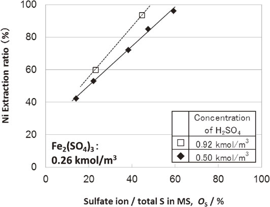
Effect of sulfuric acid concentration on MS sulfuric acid leaching tests. Sulfate ion/total S in MS vs extraction ratio.
As shown in Fig. 6, Fig. 7, although the nickel leaching ratio from MS increased to over 95%, the index of a selective leaching remained low; hence, selective nickel leaching from MS could not be achieved.
The results of the previous tests are summarized as follows.
Our findings suggest that leaching of nickel from MS has different inhibitory factors to those of selective leaching from sphalerite. There has been a report8) that zinc selective leaching from sphalerite by sulfuric acid is accompanied by considerable hydrogen sulfide generation. We hypothesized that substances formed on the reaction surface in the nickel leaching from MS were different from those yielded from zinc leaching of sphalerite. Thus, we performed sulfuric acid leaching of MS and sphalerite to confirm our hypothesis.
3.3 Sulfuric acid leaching of sulfidesThe reactions of accelerated acid leaching can be estimated from the sulfur balance of the MS and sphalerite leaching reactions with sulfuric acid. Table 2 shows the sulfur balance of MS and sphalerite leaching results. The sulfur balance was calculated by the following procedure. The reactions contributing to leaching are eqs. (11), (10), and (8). According to eq. (11), nickel is leached from MS by sulfuric acid and equal molar amounts of nickel sulfate and hydrogen sulfide are generated as a result. The generated hydrogen sulfide reacts with copper sulfate in solution and precipitates as solid copper sulfide. The sulfur content, which is generated as hydrogen sulfide in the reaction, can be confirmed by calculation of the copper sulfide weight. According to eq. (10), sulfuric acid ions, which contain an equimolar amount of leached nickel, are generated and their concentration increases in the solution. The amounts of sulfuric acid ions show no increase in eqs. (11) and (8); hence, the sulfur content, which is oxidized according to eq. (10), can be calculated from the sulfuric acid increase in the reaction.

In eq. (8), equimolar amounts of sulfur with leached nickel are generated. The generation of sulfur, based on eqs. (11) and (10) was confirmed; hence, the sulfur content generated in eq. (8) can be calculated by subtracting the sulfur content generated in eqs. (11) and (10) from the total sulfur content calculated based on the total amount of leached nickel.
The generation of zinc and other elements can be calculated in the same way. In the case of sphalerite leaching, as shown in Table 2, the breakdown of the sulfur balance in sphalerite is calculated to arise from 65% hydrogen sulfide generation, 22% as fixed residue, and 13% as sulfate ions from oxidization. However, In the case of MS leaching, the breakdown of the sulfur balance in MS is different from that of sphalerite leaching. Namely, hydrogen sulfide generation was calculated to be 5%, and 87% was fixed as residue, and 8% formed sulfuric acid ions through oxidization. The difference in the reactivity represented by hydrogen sulfide gas generation is thought to contribute to this difference of the selective leaching behavior. The morphology of the outermost surfaces of both samples and their leaching residues were examined by XPS analysis, which can identify the surface composition of the samples.
The XPS results are shown in Fig. 8 and Fig. 9(a)(b). Figure 8 shows the Zn LMM spectra of sphalerite and its leaching residue. Figure 9(a) and (b) respectively show the Ni 2p3/2 and S 2p spectra of MS, together with those of their leaching residues. The XPS database of the National Institute of Standards and Technology (NIST)9) was used to identify compounds present on the surfaces of the samples. The results in Fig. 8 indicate that zinc sulfide leached to the outmost surfaces of the raw sphalerite and the presence of its residues was confirmed. In the case of MS leaching, Fig. 9(a) and (b) were compared to confirm the outmost surface components. It is thought that nickel oxide, nickel sulfate, and nickel sulfide exist on the surfaces of the raw MS. Nickel sulfide, nickel oxide and nickel disulfide are thought to exist on the surfaces of its residue. On the basis of the results from Fig. 9(a), peaks at 860 to 863 eV in Fig. 9(a) are satellite peaks reflecting charge transfer. The results shown in Fig. 9(b) suggest that nickel sulfate and nickel sulfide were present on the outmost surface of the raw MS and nickel disulfide and nickel sulfide were present on the outmost surface of its residue. Sulfur generated in leaching was likely vaporized inside the measurement chamber, which was evacuated to high vacuum. The peaks at 168 eV in Fig. 9(b) are assigned to sulfate peaks of compounds formed in MS formation, such as sodium sulfate. By comparing Fig. 9(a) and (b), we confirmed that nickel sulfide, nickel oxide, and nickel sulfate were present on the outmost surface of the raw MS and that in addition to nickel sulfide and nickel oxide, nickel disulfide was also present on the outmost surface of the MS leaching residue. Among these compounds, nickel sulfate is thought to be an adherence compound in MS production or generated by oxidation in storage. Nickel oxide is thought to be formed by oxidation during sample drying because it is not generated by MS production or by sulfuric acid leaching. The sulfur balance in the sulfuric acid leaching and the surface analysis result by XPS, of both sphalerite and MS confirmed the following points:

XPS measurement result of Sphalerite (ZnS) and sulfuric acid leach residue.

XPS measurement result of MS and sulfuric acid leach residue. (a) Qualitative spectrum of nickel, (b) Qualitative spectrum of sulfur. 21.
The nickel disulfide on the outmost surface of the MS leaching residue is metastable and known to be a slightly soluble compound generated in sulfuric acid solution,10,11) the formation of this compound on the MS leaching residue is considered to be the main factor of preventing selective nickel leaching from MS. This assessment is also consistent with the amounts of sulfur fixed in the MS leaching residue and the balance of sulfur in the reaction.
3.4 Leaching mechanismThe reaction mechanisms of sphalerite and MS leaching by sulfuric acid solution containing iron(III) sulfate are shown in Fig. 10(a) and (b), respectively. In the case of sphalerite leaching, hydrogen sulfide was generated in the acidic solution according to eq. (4) and leaves the residue surface rapidly owing to the solution flow. The hydrogen sulfide is oxidized by iron(III) sulfate and fixed as sulfur precipitate. The absence of an inactive phase at the surface of the leaching reaction residue enables selective leaching of zinc.

Leaching reaction model of (a) Sphalerite (ZnS) and (b) MS with iron(III) sulfate in sulfuric acid solution.
Conversely, in the case of MS leaching, little hydrogen sulfide is generated by sulfuric acid and the sulfur layer formation on the MS leaching residue surface mainly proceeds simultaneously with nickel leaching by oxidation, as shown in eq. (9). As shown in eq. (12), when nickel sulfide surrounds MS and a slightly soluble NiS2 layer is generated, selective nickel leaching from MS is suppressed.
| \begin{equation} \text{S}+\text{NiS} = \text{NiS$_{2}$} \end{equation} | (12) |
The reason for the difference in the leaching reaction mechanism is discussed thermodynamically. Calculating the standard free energy change of the zinc selective reaching (eq. (1)) from sphalerite and nickel selective leaching from MS (eq. (8)) at 25°C,12,13) the calculated values are −181 and −197 kJ/mol, respectively. The difference of this value is so small, that it is impossible to explain the difference in the extraction rate between zinc and nickel. As mentioned above, the standard free energy change of hydrogen sulfide generation from sphalerite (eq. (4)) and the MS leaching (eq. (11)) at 25°C were calculated to be 29 and 13 kJ/mol. Although both standard free energies are positive, it is empirically known that hydrogen sulfide generation from sphalerite (eq. (4)) is accelerated as the sulfuric acid concentration increases. Thus, selective nickel leaching from MS likely proceeds because of the small difference of their standard free energy change. However, the standard free energy change at 25°C for NiS2 formation on the surface of the MS leaching residue (eq. (12)), as confirmed by XPS, was calculated to be −67 kJ/mol. Thus, we found that NiS2 formation proceeds more easily than hydrogen sulfide generation in equilibrium MS leaching by sulfuric acid. Hence, it is thermodynamically assumed that the formation of NiS2 layer on the MS leaching residue decreases the selective nickel leaching from MS. For the case of sphalerite leaching, a pyrite type ZnS2 layer is not formed on its residue.
Once the NiS2 layer forms on the surface of the MS leaching residue surface, partial oxidation, as shown in eq. (13), or complete oxidation as shown in eq. (14), of NiS2 is necessary to promote nickel leaching from MS.
| \begin{equation} \text{NiS$_{2}$}+\text{3/2O$_{2}$}+\text{H$_{2}$O} = \text{NiS}+\text{H$_{2}$SO$_{4}$} \end{equation} | (13) |
| \begin{equation} \text{NiS$_{2}$}+\text{7/2O$_{2}$}+\text{H$_{2}$O} = \text{NiSO$_{4}$}+\text{H$_{2}$SO$_{4}$} \end{equation} | (14) |
The MS leaching residue surface reactions shown in eqs. (13) and (14) are promoted by oxygen and new nickel sulfide surfaces become exposed; however, because the formation of NiS2 is promoted at the same time, selective nickel leaching from MS does not proceed above a certain selective leaching index. This proposed leaching mechanism is consistent with the fact that the selective leaching indexes, with the gradients shown in Fig. 6 and Fig. 7, show a constant and low value according to the reaction conditions.
It is well known that selective leaching of zinc from sphalerite by sulfuric acid is possible and is performed commercially. The applicability of this process to selective nickel leaching from MS was verified by elucidating its reaction mechanism.
The following conclusions on the selective nickel leaching mechanism from MS can be drawn:
We would like to express our appreciation to Professor Hiroyuki Fukuyama and Associate Professor Makoto Ohtsuka of Institute of Multidisciplinary Research for Advanced Materials (IMRAM) Tohoku University for their advice in reporting this study.