Abstract
In order to clarify the influence of sigma phase and hydrogen embrittlement on the mechanical properties of newly developed super duplex stainless steel F55, SSRT was conducted while performing cathodic charge. The installation potential of the constant potential SSRT was determined by polarization curve measurement. Based on the results obtained from polarization curve measurements, SSRT’s were conducted in the air, in corrosive solution, at +0.5 V constant potential, and at −0.5 V (vs. Ag/AgCl) constant potential. In order to observe the relationship between the test environment and the fracture mode, the fracture surface was observed with a scanning electron microscope and the influence of the σ phase on hydrogen embrittlement was examined. Hydrogen embrittlement was observed regardless of the amount of σ phase. As specimen having a σ phase area ratio of 30% showed larger embrittlement caused by the σ phase in air, it was suggested that σ phase embrittlement controls an embrittlement behavior. Enhancement of hydrogen embrittlement by σ phase precipitations was not observed in a cathodic charge condition used in this experiment.

1. Introduction
Duplex stainless steel is composed of austenitic phase and ferritic phase. Pitting corrosion resistance and stress corrosion cracking resistance of duplex stainless steel in chloride environment outperform those of austenitic steel and deterioration of weldability or ductility, which is a disadvantage of ferritic steel, is also improved.1) Hence, application of duplex stainless steel is extended in high chloride-containing environments such as chemical plants or seawater environments and in severe corrosion environments such as oil or gas fields where Type 304 steel or Type 316 steel cannot withstand.2) However, it was reported that sigma (σ) phase is easily precipitated in the duplex stainless steel during heating in a short period of time at around 1173 K.3,4) The σ phase is a hard and brittle intermetallic compound composed of Fe, Cr and Mo as main components and it is known that the precipitation of σ phase causes deterioration of ductility.3) Super duplex stainless steel has been reinforced its corrosion resistance in seawater environments by increasing Cr, Mo and N contents, which facilitates precipitation of σ phase and enhancement of the harmful influence on the corrosion resistance is concerned in the presence of the precipitation. As the σ phase has a high sensitivity to the hydrogen embrittlement, enhancement of hydrogen embrittlement is also concerned.5) It is generally known that duplex stainless steel is susceptible to hydrogen embrittlement. However, there are few literatures reporting-effects of the cathodic charge on mechanical properties of super duplex stainless steel. Characteristics of hydrogen embrittlement in stainless steels have been studied by performing various kinds of tensile tests after introduction of hydrogen by cathodic charges.6–11) It is generally known that the hydrogen embrittlement is strain dependent and fracture strain decreases with reduction in the strain rate.12,13) When plastic deformation takes place slowly as in the case of Slow Strain Rate Test (expressed as SSRT in short hereafter), diffusion of hydrogen can follow up dislocation movements and hydrogen atoms are trapped due to the strong interaction between dislocations and hydrogen atoms. In the case of conventional tensile test (CSRT: Conventional Strain Rate Test), plastic deformation takes place rapidly, i.e. dislocations move rapidly and hydrogen atoms cannot catch up dislocations. As interaction between them becomes weak, it is assumed that susceptibility to hydrogen embrittlement becomes lower.12,14)
In this paper, effects of σ phase and hydrogen embrittlement on mechanical properties of F55 super duplex stainless were investigated by evaluating tensile properties in the air, under natural immersion and at constant potentials using SSRT. Initially, the installation potential of the constant potential SSRT test was determined by polarization curve measurement. Based on these measurements, SSRT’s were conducted in the air, under natural immersion and at constant potentials (+0.5 V and −0.5 V vs. Ag/AgCl). Observations on fracture surfaces using a Scanning Electron Microscope (expressed as SEM in short hereafter) were also carried out to correlate the test environment to the morphology of fracture surface and influence of the σ phase on the hydrogen embrittlement was examined.
2. Experimental Method
2.1 Specimens
Newly developed F55 super duplex stainless steel was prepared and used as the specimen. Table 1 shows its chemical composition. It is comprised of 25.0%Cr, 6.6%Ni, and lower contents of Mo, W, N and others. Pitting Resistance Equivalent (PRE, PRE = mass%Cr + 3.3 × mass%Mo + 0.5 × mass%W + 16 × mass%N) shown in the lower part of Table 1 is an index indicating corrosion resistance of stainless steel. Super duplex stainless steel is defined as a one whose PRE is between 40 and 45.15) PRE of the F55 is 42.

Table 1 Chemical composition of super stainless steels F55 (mass%).
Three kinds of specimens having different σ phase area ratios were prepared to clarify the influence of σ phase and hydrogen embrittlement on mechanical properties. Amount of precipitate of σ phase was controlled by changing heat treatment temperature in a simulated manner. Temperatures of the heat treatment were 1173 K corresponding to easy precipitation zone and additional 1273 K and 1373 K.3,16) Each test piece with different area ratio of σ phase is wet-polished using water-resistant emery paper having a grit size of 80–2000 sequentially until a glossy surface appears, then buffed and then in acetone solution Ultrasonic cleaning for 300 seconds was performed. Etching was performed in a 5 mol·dm−3 NaOH solution using a Pt cathode at 6 V for 10 seconds. The observation was performed using an optical microscope. Figure 1 shows a surface texture for each specimen. Brown phases indicated by α are ferritic phases and white phases indicated by γ is austenitic phases. Black granular phases shown within the ferritic phases are σ phases. No σ phase precipitate was observed in the specimen treated at 1373 K. The σ phase precipitates were observed at the grain boundary between a ferritic phase and an austenitic phase in the specimen treated at 1273 K. The σ phase precipitated within the ferritic phase as well as in the grain boundary in a specimen treated at 1173 K. The σ phase area ratios were 30.0%, 8.9% and 0% for the specimens treated at 1173 K, 1273 K and 1373 K respectively. The lower the treatment temperature, the more the amount of precipitate.

Polarization curves were measured to fix potentials for constant potential SSRT. Figure 2 shows an experimental apparatus schematically. Test solution was a mixture of 2.5 mol·dm−3 H2SO4 + 0.2 mol·dm−3 NaCl to induce Stress Corrosion Cracking (expressed as SCC in short hereafter).17) It was prepared precisely at room temperature adjusted to 289 K using an electronic balance and a hydrometer. Residual oxygen in a test solution was purged using pure nitrogen gas. A H-shaped glass cell filled with the solution was kept in a constant-temperature bath kept at 298 K. Each specimen having a different area ratio of σ phase was wet polished until glossy surface was revealed using water resistant emery papers with grit sizes of 80 to 2000 in sequential order and 300 s ultrasound cleaning in an acetone solution was applied to obtain a final specimen. Specimen coated with a silicon rubber leaving an area of 1.0 × 10⁻⁴ m2 as an activation area was used as a working electrode. A Pt electrode was used as a counter electrode. A working electrode measured potential of the surface boundary by a Luggin capillary attached to the vicinity of an exposed surface and was collated to the referential electrode via double junction being connected to a potentiostat controlled by a computer for potential sweeping. It should be noted that potentials described in this paper were referred to an Ag/AgCl (3.33 mol·m−3 KCl) electrode. Electrode potential of the Ag/AgCl is +0.206 V at 298 K with respect to a standard hydrogen electrode (SHE). Potential was swept with sweeping rate of 0.5 mV/s between −0.5 V and +0.5 V (vs. Ag/AgCl). Surface boundary potential and current density were measured and recorded logarithmically.

Figure 3 shows a dimension of the specimen used for the tensile test. Sample size was small enough not to cause significant difference in cooling rate between bulk surface and inside of the specimen, having a parallel part of 20 mm in length, 4 mm in width and 2 mm in thickness. Specimens for tensile tests were wet polished until glossy surfaces were revealed using water resistant emery papers with grit sizes of 80 to 2000 in sequential order and 300 s ultrasound cleaning in an acetone solution was applied. Coating with a silicon rubber except a parallel part was applied to prevent influence of the solution outsides of a parallel parts. Figure 4 shows an experimental apparatus of SSRT in air and in corrosive solution. It was intended to clarify the influence of σ phase and hydrogen embrittlement on mechanical properties of the super duplex stainless steel in an environment where SCC tends to take place. In this experiment, a test solution of 2.5 mol·dm−3 H2SO4 + 0.2 mol·dm−3 NaCl mixture was kept at 298 K to facilitate SCC and degassed during 1.8 ks using high pure N2 gas. The specimen was installed in an apparatus and tensile-tested with a strain rate of 1.25 × 10⁻⁶/s. Tensile tests using a SSRT tester in the air under the same condition were also performed for comparison.

Figure 5 shows an apparatus of SSRT in constant potential schematically. This apparatus consists of a SSRT system described previously with a potential control system by a potentiostat. Mechanical properties of specimens having passivation films and those under hydrogen generation environments were investigated. Specimens were set up in an apparatus as in the case of the tensile test. As the constant potential SSRT was conducted in an immersion solution, a specimen was coated with a silicon rubber except a parallel part to prevent influence of the solution on outsides of a parallel parts and used as a working electrode. A Pt electrode was used as a counter electrode. The specimen was collated to the referential electrode of Ag/AgCl (3.33 mol·m−3 KCl) via double junction and was connected to a potentiostat to regulate the potential. Set potential was determined −0.5 V and +0.5 V (vs. Ag/AgCl) by results obtained in polarization curve measurements as described later. It was considered that absorbed hydrogen concentration in this experiment was less than 10 ppm as the potential was set at −0.5 V (vs. Ag/AgCl).18,19) After SSRT’s, fracture surfaces of specimens were observed by a SEM to evaluate morphological features of corrosion.

3. Experimental Results
3.1 Polarization curve measurements
Figure 6 shows results of polarization curve measurements for F55 super duplex stainless steel in a 2.5 mol·dm−3 H2SO4 + 0.2 mol·dm−3 NaCl solution. All curves show additional two active state peaks which are duplex stainless steel specific as well as characteristic polarization behaviors of stainless steel such as active and inactive state regions.20) Once a passivation film was formed, each specimen traced a similar curve. However, there were differences in current density among specimens in an active state region between a corrosion potential Ecorr and an inactive state potential (around −0.2 V). Larger the amount of σ phase, current density became larger. It is consistent with a previous report that precipitation of σ phase reduces surrounding Cr or Mo concentration and causing deterioration of corrosion resistance.3) According to measured polarization curves, set potentials were fixed for constant potential tests. To investigate mechanical properties in hydrogen embrittlement in this study, a potential of −0.5 V (vs. Ag/AgCl) was applied only to the parallel part of the specimen in constant potential tensile test. This potential represents the region where current density became large in polarization curve in a cathodic region. Constant potential tensile tests were also performed at +0.5 V (vs. Ag/AgCl) corresponding to an inactive state to compare mechanical properties.

Figure 7 shows stress-strain curves in the air for the specimens having σ phase area ratios of 0%, 8.9% and 30.0%. With the increased σ phase area ratio, both the ultimate tensile strength and the maximum strain decreased. Figure 8 shows those under natural immersion. As in the case in the air, both the ultimate tensile strength and the maximum strain decreased with increased σ phase area ratio. As natural immersion enhances SCC of the specimen, larger drops in both the ultimate tensile strength and the maximum strain were observed under the natural immersion environment compared to those in the air. Figure 9 shows influence of the σ phase area ratio on the ultimate tensile strength for each specimen. The ultimate tensile strengths in the air were 678 MPa, 604 Mpa and 460 MPa for the specimens with σ phase area ratios of 0%, 8.9% and 30.0% respectively. Those under natural immersion were 529 MPa, 473 MPa and 338 MPa for the specimens with σ phase area ratios of 0%, 8.9% and 30.0% respectively. Comparing the maximus stresses in the air to those under natural immersion, reductions were 22%, 22% and 27% for the σ phase area ratios of 0%, 8.9% and 30% respectively. Reduction of the ultimate tensile strength around 20% was observed in each σ phase area ratio. On the other hand, Fig. 10 shows influence of the σ phase area ratio on the maximum strain. The maximum strains in the air were 0.81, 0.48 and 0.08 for the specimens with σ phase area ratios of 0%, 8.9% and 30.0% respectively. Those under natural immersion were 0.8, 0.26 and 0.05 for the specimens with σ phase area ratios of 0%, 8.9% and 30.0% respectively. Comparing the maximum strains in the air to those under natural immersion, reductions were 0.01%, 46% and 0.4% for the specimens with the σ phase area ratios of 0%, 8.9% and 30.0% respectively. Adding a small amount of σ phase caused a significant effect on the maximum strain. Maximum strain under natural immersion was smaller than that in the air. When a σ phase area ratio reached to around 30%, the maximum strain reduced to less than 0.1 irrespective of test environments.

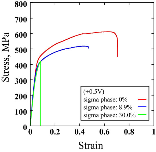
Figure 11 shows stress-strain curves of the specimens having σ phase area ratios of 0%, 8.9% and 30% in an anodic region of +0.5 V (vs. Ag/AgCl). With increase in a σ phase area ratio, reductions in both the ultimate tensile strength and the maximum strain were observed. Figure 12 shows stress-strain curves of the specimens having σ phase area ratios of 0%, 8.9% and 30% in a cathodic region of −0.5 V (vs. Ag/AgCl). It was observed that both the ultimate tensile strength and the maximum strain dropped significantly irrespective of a σ phase area ratio. Figure 13 shows an influence of the σ phase area ratio on the ultimate tensile strength of each specimen. The ultimate tensile strengths at a constant potential of +0.5 V (vs. Ag/AgCl) were 611 MPa, 512 MPa and 412 MPa for the specimens with σ phase area ratios of 0%, 8.9% and 30.0% respectively. Those at a constant potential of −0.5 V (vs. Ag/AgCl) were 393 MPa, 418 MPa and 360 MPa for the specimens with σ phase area ratios of 0%, 8.9% and 30.0% respectively. Comparing the ultimate tensile strengths at a constant potential of +0.5 V to those at a constant potential of −0.5 V (vs. Ag/AgCl), reductions were 36%, 18% and 13% for the specimens with σ phase area ratios of 0%, 8.9% and 30.0% respectively. In any σ phase area ratio, the ultimate tensile strength was higher at a constant potential of +0.5 V than that at a constant potential of −0.5 V (vs. Ag/AgCl). According to results of polarization curve measurements, a passivation film formation was enhanced by keeping potential at +0.5 V (vs. Ag/AgCl) compared to the case of natural immersion. In consequence, susceptibility to SCC caused by the existence of Cl− was reduced and this would be attributable to higher tensile strengths. On the other hand, influence of the σ phase area ratio on the maximum strain of each specimen is shown in Fig. 14. The maximum strains at a constant potential of +0.5 V (vs. Ag/AgCl) were 0.7, 0.47 and 0.09 for the specimens with σ phase area ratios of 0%, 8.9% and 30.0% respectively. Those at a constant potential of −0.5 V (vs. Ag/AgCl) were 0.07, 0.08 and 0.05 for the specimens with σ phase area ratios of 0%, 8.9% and 30.0% respectively. Comparing the maximum strains at a constant potential of +0.5 V to those at a constant potential of −0.5 V (vs. Ag/AgCl), reductions were 90%, 83% and 44% for the specimens with σ phase area ratios of 0%, 8.9% and 30.0% respectively. Influence of the σ phase area ratio on the strain was not significant at a constant potential of −0.5 V (vs. Ag/AgCl) but strain itself decreased significantly regardless of the σ phase ratio compared to that evaluated in any other test environment. This suggests that ferritic phase is influenced significantly by hydrogen embrittlement when there is no σ phase. When a σ phase area ratio reached to around 30%, ductility will be deteriorated by the σ phase embrittlement.
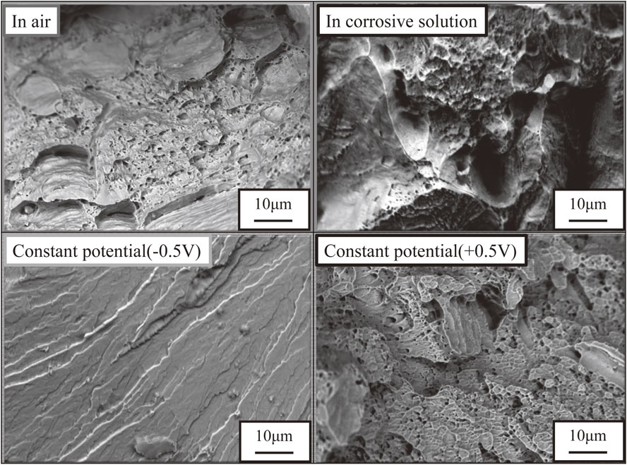
After the completion of SSRT, fracture surfaces were observed using a SEM to investigate relationships between significant decreases of strain at a constant potential of −0.5 V (vs. Ag/AgCl) and morphologies. Figure 15 shows fracture surfaces of the specimen having a σ phase area ratio of 0%. All specimens tested in the air, under natural immersion and at a constant potential of +0.5 V (vs. Ag/AgCl) showed dimples indicating that a fracture morphology is ductile fracture. On the other hand, no dimple was observed only in specimens at a constant potential of −0.5 V (vs. Ag/AgCl) and a fracture morphology was confirmed to be a brittle fracture where transgranular fractures were dominant.21) Among four environments examined in this experiment, only this environment showed transgranular fractures. A change in a fracture morphology from ductile to brittle as well as results of tensile test indicates that the ferritic phase was influenced by hydrogen embrittlement to some extent. The phase in which transgranular fractures occurred was not identified. However, it would be assumed that hydrogen atoms introduced by a cathodic charge diffused to inside of the specimen and interacted with dislocations to cause hydrogen embrittlement. Figure 16 shows fracture surfaces of specimen having a σ phase area ratio of 8.9%. No dimple was observed among specimens tested in the air, under natural immersion or at a constant potential of +0.5 V (vs. Ag/AgCl). As a fracture morphology of the specimens having a σ phase area ratio of 0% in these conditions was a ductile fracture, it was confirmed that a fracture morphology changed to a brille fracture. Precipitation of the σ phase commonly known as a hard and brille phase is assumed to cause deterioration of toughness of the duplex stainless steel. Figure 17 shows fracture surfaces of a specimen having a σ phase area ratio of 30%. As in the case of a specimen having a σ phase area ratios of 8.9%, fracture morphologies were brittle fractures in all test environments and the embrittlement of the duplex stainless steel was confirmed. In test environments in this study, influence of hydrogen embrittlement was partially observed in a fracture surface as transgranular fractures after a cathodic charge at a constant potential of −0.5 V (vs. Ag/AgCl). However, precipitation of the σ phase is assumed to be dominant. Indication of susceptibility of the σ phase to hydrogen embrittlement was not observed. It was suggested that hydrogen is not so influential in spite of some contributions to grain boundary embrittlement in each phase boundary or transgranular embrittlement.
4. Discussion
A previous study reported tensile test results of duplex stainless steel after cathodic charges. Specimens they used had a pseudo-duplex structure composed of austenitic phase and σ phase induced by heat treatments.19) They concluded that σ phase is highly susceptible to hydrogen embrittlement.19) However, tensile tests of F55 super duplex stainless steel in conjunction with cathodic charges in this experiment did not support them. Nearly same ultimate tensile strengths and maximum strains were observed in all specimens having σ phase area ratios of 0%, 8.9% and 30%, showing no correlation between the σ phase area ratio and hydrogen embrittlement. Elongation was not observed in the specimen with a σ phase area ratio of 30% and hydrogen embrittlement would not be recognized even after a few ppm of hydrogen was charged. In duplex stainless steel, σ phase is formed in the ferritic phase region and hydrogen embrittlement takes place mainly in the ferritic phase. Therefore, influence of hydrogen embrittlement would be hidden by a larger effect of the σ phase embrittlement. Figure 13 shows the ultimate tensile strength curves obtained in SSRT tests. Ultimate tensile strengths at a constant potential of −0.5 V were 394 MPa corresponding to 26% reduction compared to that under natural immersion and 360 MPa corresponding to 6% increase compared to that under natural immersion for the specimens with phase area ratios of 0% and 30.0% respectively. Figure 14 shows the maximum strain curves. The maximum strains at a constant potential of −0.5 V were 0.07 corresponding to 91% reduction compared to that under natural immersion and same 0.05 to that under natural immersion for the specimens with σ phase area ratios of 0% and 30.0% respectively. Reduction ratios of both the ultimate tensile strength and the maximum strain of the specimen with a σ phase area ratio of 30% were smaller than those of the specimen with a σ phase area ratio of 0% in the air and at a constant potential of −0.5 V (vs. Ag/AgCl). Therefore, it cannot be said that a susceptibility to hydrogen embrittlement is significantly high when the σ phase area ratio is high. Specimen with a σ phase area ratio of 30.0% showed σ phase embrittlement around 200 MPa in the air. Comparison of specimens with a σ phase area ratio of 0% in an anodic environment and after a cathodic charge, hydrogen embrittlement around 200 MPa was also observed. It is considered that all these deteriorations take place in the ferritic phase and deterioration of the ferritic phase would be mainly controlled by the σ phase embrittlement.
In the case of Nakade’s study, they used the pseudo-duplex specimens, which consist of austenite and sigma phase by heat treatment at 1023 K. Under the heat treatment, most of ferrite transformed to secondary austenite. Therefore, it is thought that the regions of original ferrite grains have large residual stress in the regions. Nakade et al. assumed that the significant hydrogen embrittlement depends on their sensibility of the embrittlement of sigma phase or strength of sigma/austenite phase boundary from the result of fracture surface observation. However, we assume that the residual stress induced by phase transformation of secondary austenite enhance the hydrogen embrittlement in the conditions.
5. Conclusions
Influence of σ phase and hydrogen embrittlement environments on mechanical properties of duplex stainless steel was investigated. Experimental findings were as follows:
-
(1)
Measurements of polarization curve showed that each specimen traced a similar curve once a passivation film was formed. However, some specimens showed difference in current density in an active region between a corrosion potential Ecorr and an inactive region (around −0.2 V). In these specimens, an anodic reaction was enhanced with increased σ phase area ratio and a corrosion resistance consequently deteriorated with increased amount of σ phase.
-
(2)
Results of tensile tests and constant potential tests showed that some amount of hydrogen embrittlement was introduced with small amounts of hydrogen. As specimen having a σ phase area ratio of 30% showed larger embrittlement caused by the σ phase, it was suggested that σ phase embrittlement controls an embrittlement behavior. Enhancement of hydrogen embrittlement by σ phase precipitations was not observed in a cathodic charge condition used in this experiment.
-
(3)
SEM observations on fracture surfaces showed that a fracture morphology was a ductile fracture in F55 super duplex stainless steel specimens having a σ phase area ratio of 0% tested in the air, under natural immersion and at a constant potential of +0.5 V (vs. Ag/AgCl). Once a small amount of σ phase was introduced, fracture surfaces showed brittle fractures irrespective of test environment and ductility decreased significantly compared to that of specimens without σ phase. However, in a hydrogen generating environment at a constant potential of −0.5 V (vs. Ag/AgCl), a brittle fracture was observed where transgranular cracks were dominant. Despite non-existence of σ phase in a fracture surface, reduction in ductility was confirmed. Then, influence of hydrogen embrittlement was suggested.
REFERENCES
- 1) M. Murata, J. Wang and Y. Mukai: Zairyo-to-Kankyo 40 (1991) 461–469.
- 2) S. Aoki: Zairyo-to-Kankyo 65 (2016) 45–50.
- 3) K. Nakade, K. Ohe and T. Kuroda: Q. J. Jpn. Weld. Soc. 19 (2001) 92–99.
- 4) K. Nakade and T. Kuroda: J. High Temp. Soc. 33 (2007) 95–100.
- 5) K. Nakade and T. Kuroda: Zairyo 54 (2005) 215–220.
- 6) P. Craidy, L. Briottet and D. Santos: Int. J. Hydrogen Energ. 40 (2015) 17084–17090.
- 7) T. Omura and J. Nakamura: Zairyo-to-Kankyo 60 (2011) 241–247.
- 8) T. Omura, K. Tomatsu, Y. Sakiyama, K. Sugita, M. Mizuno, H. Araki and Y. Shirai: Tetsu-to-Hagané 104 (2018) 655–663.
- 9) K. Koide, T. Minami, T. Anraku, A. Iwase and H. Inoue: Zairyo-to-Kankyo 63 (2014) 523–527.
- 10) Y.-S. Kim and J.-G. Kim: Int. J. Hydrogen Energ. 42 (2017) 27428–27437.
- 11) W. Wu, Z. Liu, S. Hu, X. Li and C. Du: Ocean Eng. 146 (2017) 311–323.
- 12) G. Kitahara, A. Tsuji, T. Sada, T. Suzuki, K. Horikawa and H. Kobayashi: Zairyo-to-Kankyo 68 (2019) 46–52.
- 13) A. Yousefi and G. Itoh: ISIJ Int. 58 (2018) 561–565.
- 14) T. Chida, Y. Hagihara, E. Akiyama, K. Iwanaga, S. Takagi, H. Ohishi, M. Hayakawa, D. Hirakami and T. Tarui: Tetsu-to-Hagané 100 (2014) 1298–1305.
- 15) J.-S. Lee, K. Fushima, T. Nakanishi, Y. Hasegawa and Y.-S. Park: Corros. Sci. 89 (2014) 111–117.
- 16) K. Ogawa and T. Osuki: Q. J. Jpn. Weld. Soc. 33 (2015) 55–61.
- 17) S. Sunada, M. Kariba, K. Majima and K. Sugimoto: Mater. Trans. 47 (2006) 364–370.
- 18) T. Omura et al. Tetsu-to-Hagané 100 (2014) 1289–1297.
- 19) K. Nakade and T. Kuroda: Zairyo 54 (2005) 239–244.
- 20) S. Aoki, K. Ito, H. Yakuwa, M. Miyasaka and S. Jun’ichi: Zairyo-to-Kankyo 60 (2011) 363–367.
- 21) C. Roberto de Farias Azevedo, H. Boschetti Pereira, S. Wolynec and A. Fernando Padilha: Eng. Fail. Anal. 97 (2019) 161–188.


