2. Experimental Procedures
2.1 Hydrogen permeation experiments using electrogalvanized steel
The amount of hydrogen absorbed into the electrogalvanized steel was measured by electrochemical hydrogen permeation tests, which were conducted using a Devanathan-Stachurski cell.10,11) Figure 1 illustrates the schematic drawing of the cell. The cell consisted of an electrolytic vessel made of a transparent vinyl chloride-based resin with two chambers. Each chamber contained a reference electrode and platinum foil counter electrode connected to a potentiostat/galvanostat (HA-151B, Hokuto Denko). An Hg/HgO electrode in 1 mol/L NaOH and an Ag/AgCl electrode in saturated KCl were respectively used as reference electrodes for the hydrogen detection and the hydrogen entry chambers. The exposed surface areas of both sides were maintained at 0.67 cm2.

A commercial electrogalvanized steel sheet, with a thickness of 0.6 mm (SECC defined in JIS, purchased from Toho Kogyo), was used for the hydrogen permeation experiments. The zinc coating on one or both sides was removed by dipping the samples in a solution containing 7% HCl and 0.5% hexamethylenetetramine until the spontaneous potential of the sample was −0.35 V vs. Ag/AgCl. When the zinc coating on one side of the sample removed, the other side was covered with a rubber sealant. After the zinc coating was dissolved completely, a thin nickel layer, 100 nm thick, was deposited on the zinc-stripped side of the samples using RF magnetron sputtering (EB1000, Canon Anelva) at 25°C. All samples were washed with ultra-pure water and acetone before further testing.
The prepared sample was clamped between the two chambers for testing. The hydrogen detection side chamber was filled with a 0.1 mol/L NaOH solution and a potential of +0.15 V vs. Hg/HgO was applied. The Ni-coated surface of the sample was placed in 0.1 mol/L NaOH solution for over 12 h to attain the background current density. When a background current density in the range of +0.02–+0.03 µA·cm−2 was detected, the hydrogen entry side chamber was filled with 3% NaCl or a solution with pH 2, containing 3 mass% NaCl adjusted with HCl, to measure the hydrogen permeation current density (jH) and corrosion potential (Ecorr) during the immersion corrosion tests. The hydrogen detection side of the sample was potentiostatically maintained at +0.15 V vs. Hg/HgO during the permeation tests. All immersion corrosion tests were continued for over 80 ks at 25°C.
2.2 Hydrogen permeation measurements of a zinc–iron galvanic couple
Hydrogen permeation tests were conducted using the cell described in Fig. 1 to evaluate the amount of the hydrogen absorbed during the sacrificial dissolution of the zinc coating i.e., the formation of a zinc–iron galvanic couple. Figure 2 shows the schematic of the experimental system. The hydrogen detection side chamber was similar to the setup in Fig. 1. The hydrogen entry side chamber contained an Ag/AgCl reference electrode in saturated KCl and zinc sheets of thickness 0.6 mm and purity 99% (purchased from Nilaco) or electrogalvanized steel (purchased from Toho Kogyo) counter electrode. The counter electrode forming the galvanic couple was placed 10 mm from the sample. One side of the counter electrode was covered with rubber sealant, while the other side of the counter electrode, which had an exposed surface area of 6.7 cm2, was placed facing the sample. The hydrogen detection side chamber was connected to a potentiostat/galvanostat (HA-151B, Hokuto Denko) and a zero shunt ammeter (HB-102A, Hokuto Denko).
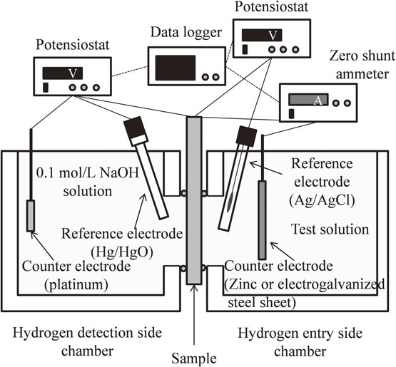
Commercial iron sheets of thickness 0.2 mm and purity 99.5% (purchased from Nilaco) were used in this test. A thin nickel layer, 100 nm in thickness, was deposited on the hydrogen detection side of the samples using RF magnetron sputtering at 25°C. All samples were washed with ultra-pure water and acetone before further testing. The potential applied during the permeation tests was the same as described in section 2.1.
The hydrogen entry side chamber was filled with the test solution, which was 3% NaCl solution adjusted to pH 2–14 with HCl or NaOH. The sample was connected to the reference electrode via a potentiostat/galvanostat and the counter electrode via a zero shunt ammeter to measure Ecorr, jH and jgal (galvanic current density) during the sacrificial dissolution of zinc. All immersion corrosion tests were performed for over 30 ks at 25°C.
2.3 Hydrogen permeation experiments to evaluate the influence of zinc ion on hydrogen absorption
Hydrogen permeation experiments were conducted using the cell shown in Fig. 1 to evaluate the influence of zinc ions in the solution on the amount of absorbed hydrogen. Sample preparation and pretreatment were similar to those described in section 2.2. The test solution in the hydrogen entry side chamber contained 3% NaCl and 10 mM ZnCl2, and was adjusted to pH 2, 7, or 14 using HCl or NaOH. Potentials equal to Ecorr obtained in section 2.2, which were −1.0 V vs. Ag/AgCl for pH 2 or pH 7 solutions and −1.45 V vs. Ag/AgCl for pH 14 solution, were applied on the hydrogen detection side. The cathodic potential (Ec), cathodic current density (jc), and jH were measured during cathodic charging in the zinc ions solutions. All experiments were performed for over 80 ks at 25°C.
3. Results and Discussions
3.1 Hydrogen permeation measurements for electrogalvanized steel
Figure 3 shows the transients of jH and Ecorr of the galvanized steel during the immersion experiment conducted in the 3% NaCl solution. During the immersion corrosion test, Ecorr exhibited a negative potential of about −1.0 V and did not change considerably, while jH started to increase at about 15 ks after the immersion. This indicates that the diffusion rate of hydrogen in the zinc coating was low21,22) when the coating was intact. Subsequently, jH fluctuated from 20 ks to 45 ks, and t remained steady at a value of about 2 µA·cm−2. It is supposed that the hydrogen evolution reaction was suppressed by the formation of corrosion products on the zinc coating or in defects; thus, jH was decreased. When the corrosion products were desorbed, the hydrogen generation reaction occurred again in areas occupied by the corrosion products, and resulted in an increase in jH. Therefore, the fluctuation in jH can be attributed to the repetition of the above phenomena.

Figure 4 illustrates the transients of jH and Ecorr of the galvanized steel without zinc coating on the hydrogen entry side, during the immersion test conducted in 3% NaCl solution adjusted to pH 2. The initial part of Fig. 4(a) is amplified and displayed in Fig. 4(b). Ecorr varied slightly at the beginning and remained constant at about −0.52 V during the rest of the immersion corrosion test. However, jH began to increase 200 s after immersion and stayed at 2.5 µA·cm−2. The diffusion coefficient was calculated using eq. (1):23)
| \begin{equation}
T_{\text{B}} = 0.5L^{2}/\pi^{2}D
\end{equation}
| (1) |
where,
L is the thickness of the steel sheet,
D is the diffusion coefficient in steel, and
TB is the breakthrough time shown in
Fig. 4(b). The diffusion coefficient of hydrogen in steel was calculated as 9.1 × 10
−7 cm
2·s
−1 by substituting
TB of this study (200 s) in
eq. (1).
Figure 5 illustrates the transients of jH and Ecorr of the galvanized steel during the immersion test conducted in a 3% NaCl solution adjusted to pH 2. The surface appearances of the sample at time A, B, C, and D are also shown in the same figure. The changes in Ecorr and jH are divided into four regions, (i) to (iv). Ecorr was nearly constant at about −1.0 V in regions (i) and (ii) until 33 ks. jH was not detected in region (i); thus, the zinc coating was intact and the steel sheet was almost entirely covered by the zinc coating (photo A).

In region (ii), at about 8 ks, jH started increasing gradually. The time required for jH to start increasing was longer for galvanized steel than for steel without the zinc coating (Fig. 4) because the hydrogen diffusion coefficient of zinc is lower in zinc than in steel.21,22) In a previous work, the hydrogen diffusion coefficient in a 2.2 µm-thick zinc coating was 5 × 10⁻¹² cm2·s−1.22) This value is significantly smaller than the value in steel, obtained using eq. (1) in this study. The slope of the hydrogen permeation curve in region (ii) was smaller than that of galvanized steel without the zinc coating. In addition, slight pitting was observed in region (ii) (photo B). It is supposed that the through-thickness pits, which exposed the substrate, formed following the partial dissolution of zinc coating. However, red rust originating from the steel substrate was not observed in this region. Therefore, the zinc coating probably provided the sacrificial protection for the steel, because hydrogen evolution occurred in the exposed areas of the substrate and jH was detected. Furthermore, as the exposed substrate area was small and increased only slightly, jH was also small and increased only slightly. Hence, the slope of the hydrogen permeation curve in this region was probably caused by the gradual increase in hydrogen evolution with time due to the pitting corrosion.
Ecorr increased rapidly to a large value in region (iii); jH also increased rapidly to its maximum value shortly after the rapid increase in Ecorr. Then, jH decreased with a slight increase in Ecorr. The peak current density during hydrogen permeation was about 16 µA·cm−2. In region (iii), as Ecorr increased rapidly to a large value, the steel substrate was almost exposed entirely, and only some zinc coating remained (Fig. 5(C) and Fig. A1). This is because zinc is less noble than iron. The hydrogen diffusion coefficient of zinc is lower than that of steel and suppresses hydrogen permeation, while iron, which has a low overvoltage for hydrogen evolution, supports higher hydrogen evolution and absorption. Moreover, the hydrogen evolution reaction occurred on the exposed steel substrate instead of the zinc dissolution reaction. Thus, jH increased quickly. When Ecorr reached −0.53 V, no zinc coating remained and the entire steel substrate was exposed. As the hydrogen evolution due to zinc dissolution reaction finished and the hydrogen evolution occurred only due to iron corrosion, jH began to decrease. Consequently, both Ecorr and jH changed drastically in this region.
In region (iv), jH decreased and Ecorr remained stable at −0.53 V. In this region, sacrificial protection no longer functioned as the zinc coating had dissolved completely and rust was observed in some spots. jH decreased as hydrogen evolution occurred only from iron corrosion and remained at 2.5 µA·cm−2 eventually.
3.2 Hydrogen permeation measurements during the formation of zinc–iron galvanic couple
The results in section 3.1 revealed that the sacrificial dissolution of the zinc coating increased the jH. If the value of jH in the steady state of a zinc–iron galvanic couple is known, the amount of absorbed hydrogen can be calculated from the hydrogen concentration at the surface using the following equation:23,24,25)
| \begin{equation}
C_{\text{ab}} = 1.318\times j_{\text{H},\,\infty}\times L/D
\end{equation}
| (2) |
where,
jH, ∞ is the value of
jH at the steady state,
L is the thickness of the iron sheet,
Cab is the hydrogen concentration at the surface, and
D is the diffusion coefficient of hydrogen. Here,
D is constant, whereas
L is constant as long as iron is not corroded after the loss of its sacrificial corrosion protection.
However, it is difficult to obtain the value of jH in the steady state of a zinc–iron galvanic couple using the standard hydrogen permeation test on galvanized steel as the sample surface changes drastically when the coating is dissolving.
Therefore, further experiments were performed using the methods described in section 2.2 to evaluate the amount of hydrogen absorbed during the formation of the iron and zinc galvanic couple.
Figure 6 illustrates the transients of jH, Ecorr and jgal of the galvanic couple formed by an iron sheet and zinc sheet in a 3% NaCl solution adjusted to pH 2. Ecorr was nearly constant at −1.0 V while iron and zinc sheets formed a galvanic couple. jgal fluctuated and exhibited a downward trend from the beginning of immersion until 12 ks; subsequently, it fluctuated and became constant. jH increased immediately and the curve acquired a sigmoidal shape, which is a typical feature of hydrogen permeation curves. Thereafter, jH exhibited a steady state from the beginning of the test until nearly 2 ks and subsequently remained approximately constant (i.e., in a steady state). After the steady state period, the fluctuations in jH seemed to correspond with the variation in jgal. The fluctuations in jH and jgal indicate reaction instability due to the adhesion and desorption of gas generated on the specimen during the dissolution of zinc. When the coupled iron sheet and zinc sheet were disconnected from the zero shunt ammeter at 35 ks, Ecorr shifted to the potential of corrosive iron at −0.53 V (see Fig. 4), and jH decreased quickly.

Figure 7 shows the transients of jH, Ecorr, and jgal of the galvanic couple formed by the iron sheet and a zinc sheet in 3% NaCl solution (pH 6.85). Ecorr was nearly constant at −1.0 V as it was in an acidic solution. jgal decreased after the beginning of the test and eventually remained nearly constant at 0.04 mA·cm−2. jH began to increase at 1 ks and eventually became constant at 7 µA·cm−2. Fluctuations similar to those in the acid immersion experiment were not observed in the jgal and jH curves.

Figure 8 shows the transients of jH, Ecorr, and jgal of a galvanic couple formed by the iron sheet and a zinc sheet in 3% NaCl solution adjusted to pH 14. Ecorr was nearly constant at −1.45 V. jH began to increase rapidly from around 400 s, attained a maximum value of 22 µA·cm−2 around 2 ks, and then gradually decreased to a constant value of 5 µA·cm−2. jgal recorded a high value of 8 mA·cm−2 at the beginning of the test and then decreased gradually before becoming constant at 0.15 mA·cm−2. The decreases in both jH and jgal can be attributed to the large amount of dissolved zinc ions accumulated in the solution.
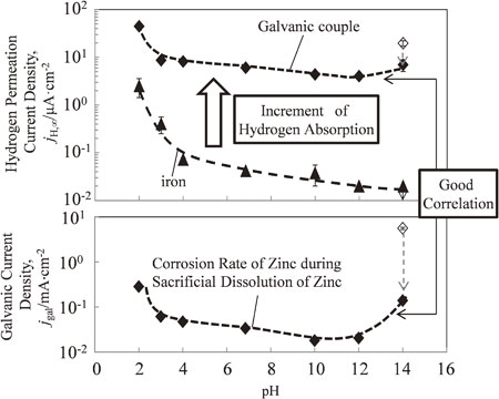
Figure 9 depicts the variation in the mean values of jH, ∞, Ecorr, and jgal in the steady state as a function of pH, when iron and zinc formed a galvanic couple (closed diamonds), and when the iron without zinc corrosion was tested (closed triangles). The open diamond symbols indicate the maximum value in the test using pH 14 alkaline solution.
The increase of jH, ∞, for the iron–zinc galvanic couple was larger than that for iron at all tested pH values. This suggests that hydrogen absorption was promoted by the formation of the iron–zinc galvanic couple.
The Ecorr of iron without zinc was between −0.6 V and −0.7 V in the pH range of 2–12, but increased −0.2 V at pH 12. In contrast, when iron and zinc formed a galvanic couple, the Ecorr decreased below the Ecorr of the iron, to −1.0 V in the pH range 2–12, and −1.4 V at pH 14.
The pH dependence of jgal demonstrated a parabolic curve (opening upward). jgal was relatively low in the pH range of 7–12, primarily due to the formation of a protective film of corrosion products on the zinc surface. However, jgal increased considerably on either side in the pH range 7–12 because zinc is an amphoteric metal and dissolves readily in acidic or strongly alkaline solutions. The pH dependence of jgal was similar to the pH dependence of the zinc corrosion rate described in previous reports.26–28)
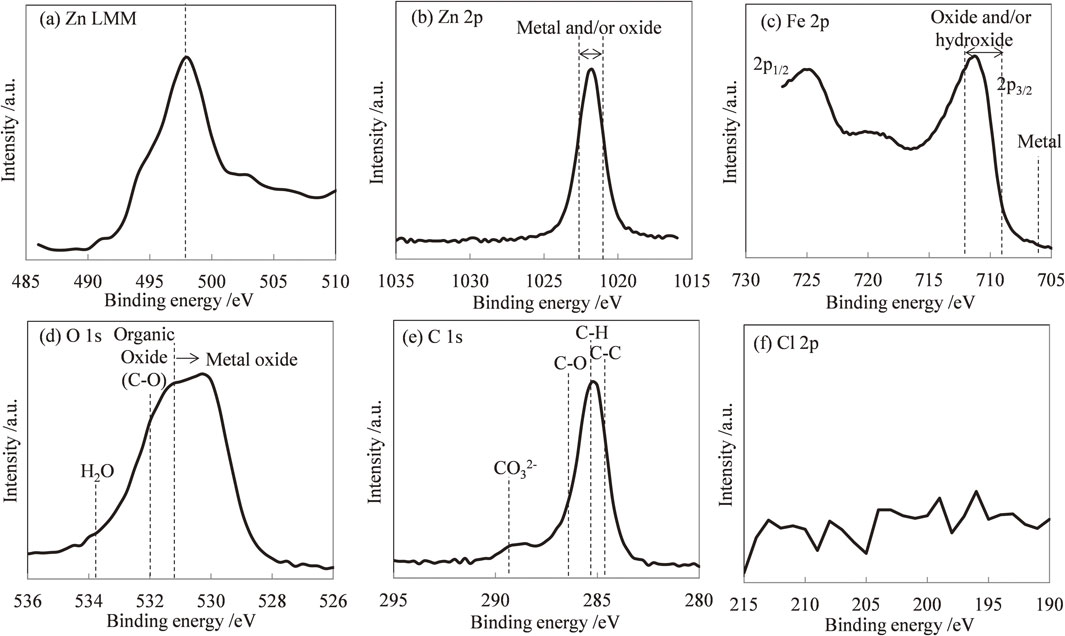
For the iron, jH, ∞ decreased as the pH increased. Hydrogen evolution reactions have been observed mainly in acid solutions with pH values below 4, indicating that hydrogen absorption occurred at these pH values. Furthermore, at pH values below 4.0, all of the iron oxide (FeO) dissolved on the metal surface. In the absence of a protective iron oxide layer that protects iron from corrosion and inhibits hydrogen absorption, the metal surface is in direct contact with the acid solution, and extensive corrosion reactions and hydrogen absorption occur. As a result, it is assumed that jH, ∞ increased in acid solutions with pH values below 4. In the pH range 4–10, jH, ∞ was relatively independent of the solution pH, and the corrosion rate was governed largely by the rate at which oxygen reacted with the absorbed hydrogen. The oxygen reduction reaction was constant regardless of the pH. For pH values above 10, the corrosion rate decreased as the pH increased. In alkaline solutions with pH above 10, a protective Fe2O3 oxide layer formed. The layer protected iron from corrosion and inhibited hydrogen absorption, and jH, ∞ decreased as the pH increased. During the formation of the iron–zinc galvanic couple, the relationship between jH, ∞ and pH was approximately the same as that between jgal and pH. This is possibly due to the same reasons that explained the variation of jgal. As the hydrogen overpotential is low on the surface of iron, hydrogen evolution occurs at the potential (Ecorr) at which iron forms a galvanic couple with zinc. Further, hydrogen evolution occurs at the same rate as zinc dissolution at the surface of iron; the hydrogen flux into iron changes accordingly. As a result, trends of changes in jH, ∞ and jgal appeared the same. However, at pH 14, the increase in jH, ∞ was smaller than that in jgal. To assess the decreases in jH and jgal of the galvanic couple at pH 14, scanning electron microscopy (SEM) images and energy dispersive X-ray spectroscopy (EDS) profiles of iron tested in the pH 14 solution (Fig. 10) were examined. Many acicular objects were observed on the iron sheet, and Zn was detected in the objects. Figure 11 shows the Zn LMM Auger spectrum and Zn 2p, Fe 2p, O 1s, C 1s and Cl 2p XPS spectra of an iron sheet tested in an alkaline solution of pH 14. A Quantera SXM (ULVAC PHI) was used to perform the X-ray photoelectron spectroscopy (XPS). Monochromated Al Kα radiation (1486.6 eV) was used as the excitation source. The Zn LMM spectrum was employed because the binding energy between Zn2+ and Zn is small in the Zn 2p spectrum29) (Fig. 11(b)). The peaks observed in Fig. 11(a) were attributed to simonkolloeite (Zn5(OH)8Cl2·H2O) or hydrozincite (Zn5(CO3)2(OH)6).29–31) The Fe 2p spectra originate from the iron sheet and exhibit typical features of the oxide and/or iron hydroxide. The O 1s spectrum is a complex peak consisting of peaks related to metal oxides and organic oxides (C–O). The peak related to H2O was not observed. Two peaks were observed in C 1s spectra. The first peak was complex, consisting of peaks related to the adventitious carbon state of C–C, hydrocarbon C–H and organic C–O. The second peak was ascribed to carbonate (CO3)2+. Cl 2p spectra were not observed (Fig. 11(f)). From the results of the XPS spectra, the acicular objects observed in the SEM images were assumed to be hydrozincite. We proposed that jgal and jH decreased because the hydrogen evolution was suppressed as the iron surface was covered with hydrozincite.

A hydrogen permeation test was performed using electrogalvanized steel instead of a zinc sheet. Figure 12 compares the jH, ∞, jgal, and Ecorr values obtained following hydrogen permeation tests using zinc sheets and electrogalvanized steel. No significant differences were observed between the electrogalvanized steel and zinc sheet counter electrode. Therefore, the experimental method proposed in this study can be used to quantitatively evaluate the influence of various surface treatment layers on hydrogen absorption during sacrificial dissolution.
3.3 Hydrogen permeation experiments for evaluating influence of zinc ions in solution on hydrogen absorption
To evaluate the influence of zinc ions in solution on hydrogen absorption, a hydrogen permeation test was conducted by cathodic hydrogen charging using a solution containing 10 mM zinc ions. Figure 13 shows the variations in jH, ∞, Ec, and jc as functions of pH in solutions with and without 10 mM zinc ions. The open squares denote solutions with 10 mM zinc ions and the closed squares denote the solutions without zinc ions. Ec was the same as in experiments on the zinc–iron galvanic couple. In the entire pH range, both jc and jH, ∞ were smaller for solutions with zinc ions than solutions without zinc ions. Particularly, both jc and jH, ∞ decreased at pH 14, jH, ∞ at pH 14 was smaller than that at pH 7. Figure 14 shows the SEM images and EDS profiles of the iron sheet after experiment. Although particulate objects were observed locally, Zn was not detected by EDS at pH 2. At pH 7, thinner microplate-like objects were observed and high-intensity peaks originating from Zn, Cl, and O were detected in the EDS profile. These objects exhibited morphology similar to simonkolleite, which was observed in other research.32) The morphology and EDS profiles indicate that the objects were simonkolleite. Many fine acicular objects were observed on the iron sheet, and Zn was detected from the objects at pH 14. In addition, the sample at pH 14 was also characterized by XPS to identify the acicular objects. Figure 15 shows the Zn LMM Auger spectra and Zn 2p, Fe 2p, O 1s, C 1s and Cl 2p XPS spectra of an iron sheet tested in an alkaline solution at pH 14 with addition of 10 mM Zn2+. Spectra similar to Fig. 11 were obtained. Therefore, the acicular objects observed in Fig. 14(c) were also identified as hydrozincite. This indicates that hydrogen evolution and absorption are largely inhibited by zinc compounds such as hydrozincite and simonkolleite deposited on the surface of iron by the cathodic charging in a solution containing zinc ions. Here, the galvanic couple and cathode charge have the same effect. Although a zinc-derived substance was not observed in the pH 2 sample, both jc and jH, ∞ decreased. It is probable that only few zinc-containing objects precipitated during the test, but were removed due to the dissolution of the iron surface.


The results of the present research indicate that galvanization promotes hydrogen absorption in solutions at all pH values when the substrate is exposed following Zn dissolution. However, hydrogen absorption was inhibited when zinc dissolution progressed and zinc ions accumulated. Therefore, the following points should be considered when using galvanized steel is used. In the wet-dry environments such as atmospheric corrosion, hydrogen absorption is not significantly promoted because of the inhibitory effect of the corrosion products and accumulation of ions. On the contrary, in environments frequently exposed to rainwater or seawater, a large amount of hydrogen will be absorbed and hydrogen embrittlement may be promoted as protection by corrosion products of zinc is lost and ion accumulation does not occur.