Modeling and Crystal Plasticity Simulations of Lath Martensitic Steel under Fatigue Loading
2018 Volume 60 Issue 2 Pages 199-206

Details
2018 Volume 60 Issue 2 Pages 199-206
A computational study for the modeling of lath martensitic steels, considering morphological and crystallographic features, is presented. A two-dimensional multi-scale tessellation is proposed to generate idealized microstructures with several scales of heterogeneities. The proposed approach is applied to lath martensite where prior austenite grain, packet and block boundaries are explicitly considered as well as their crystallographic relationships. The role of the different sources of heterogeneity on fatigue crack initiation is then investigated by finite element simulations including a single-crystal plasticity model. A fatigue criterion based on the Tanaka-Mura model is evaluated. The results indicate that block morphology and their orientation relationship significantly affects the strain distribution and the predicted location of crack initiation. In this regard, the effective critical size for crack initiation in low-carbon steels appears to be the block size as the Tanaka-Mura model mainly predicts cracks initiation along the block direction.
Lath martensitic steels exhibit excellent strength and hardness directly related to their unique hierarchical structure composed of laths, blocks and packets.1) In contrast to single-scale metals, this multi-scale microstructure presents a significantly heterogeneous deformation behavior at the grain scale due to the specific morphological-crystallographic relationship induced by the martensitic transformation.2–4) Assuming {110}⟨111⟩ and {112}⟨111⟩ families as potential slip systems, Michiuchi et al.2) experimentally inferred by in-situ backscatter diffraction (EBSD) analyses during a tensile test, that {110} in-lath-plane slip systems, where the Burgers vector belongs to lath plane, were preferably activated. Nambu et al.3) enriched this work by observing a transition in the deformation mechanism under a high-strain regime where out-of-lath-plane slip onsets leading to an increased work-hardening. Combined with the fact that block interfaces have high misorientation angles, the Hall-Petch type effective grain size was therefore regarded as the block size.5) Failure in lath martensite under fatigue loading has been experimentally investigated by Meyer et al.6) In the absence of inclusions, micro-cracks preferentially initiate parallel to the lath interfaces as a direct consequence of the propensity for in-lath-plane slip to be activated under low-strain amplitude. These investigations emphasized the complex multi-scale nature of lath martensite and its intrinsic microstructure-property relationship.
With the improvement in computer capacities and the deeper empirical and theoretical understanding of damage mechanisms, a material-oriented design approach based on the prediction of the performance through the modeling of the material at a certain scale is a recent trend to bridge the microstructure-property relationship. The mechanical behavior is generally assessed by full-field simulations such as the finite element method (FEM) where experimentally based or synthetic polycrystals are explicitly modeled and often combined with a single crystal formulation for their elasto-plastic behavior.7) Applied to fatigue problems, the local mechanical fields are used to evaluate fatigue indicator parameters (FIPs) that translate from a micro-mechanical point of view the mechanisms responsible for crack initiation.8,9) In this regard, an accurate estimation of local fields requires a realistic representation of the material that reproduces key microstructural features. Bertolino et al.10) indeed emphasized the limited accuracy of the deformation fields evaluated from a Voronoi tessellation when grains present a small aspect ratio as it fails to account for higher moments of statistical distributions of grain shape. Besides, to catch the variability inherent to fatigue, simulation of a large group of statistically similar polycrystals is necessary so that systematic methodology for their modeling is needed. Osipov et al.11) proposed an approach based on the cutting of Voronoi cells to generate bainitic grains composed of multiple packets. While it takes into account crystallographic orientation relationship (OR), the method does not provide any control on the morphology-orientation relationship so that a systematic methodology for the modeling of lath martensite is still currently lacking.
The purpose of the present study is therefore to develop a robust methodology for the modeling of lath martensite taking into account microstructural and crystallographic features as well as their intrinsic relationship and to investigate their role on the local mechanical fields and on the prediction of crack initiation under fatigue condition using the crystal plasticity finite element method (CPFEM). The paper is organized as follows. In Section 2, the main microstructural features of lath martensite are summarized and a detailed framework for the generation of two-dimensional multi-scale tessellations is presented. The simulation conditions, crystal plasticity constitutive model, and investigated fatigue criterion are described in Section 3. The results are finally presented and discussed in regard to the modeling hypotheses in Section 4.
The transition from the parent austenite (γ) to the child martensite (α′) occurs following specific OR. The interface between the martensite and the prior austenite is referred as the habit plane. In low-carbon steel, the Kurdjumov-Sachs12) (KS) OR is mainly observed:
| \begin{equation} \{111\}_{\gamma}\parallel\{011\}_{\alpha'};\langle\bar{1}01\rangle_{\gamma}\parallel\langle\bar{1}\bar{1}1\rangle_{\alpha'}, \end{equation} | (1) |

(a) (110) pole figure of the 24 KS variants of a [100] prior austenite crystal. (b) Schematic illustration of the lath long directions of the different variants of the KS ORs.
To characterize the microstructure of lath martensite, the description proposed by Morito et al.1) is adopted. Packets are defined as groups of laths sharing the same habit plane and blocks correspond to groups of laths sharing the same direction. Experimental investigations on low-carbon steels revealed that all the variants of the KS ORs tend to be present in equal proportion within a prior austenite grain as long as the martensitic transformation is complete.1,13) In addition, lath long direction tends to parallel {011}α′ planes within each packet as a probable consequence of block growth along {111}γ planes of the prior austenite grain.1,13) Figure 1(b) represents the lath long direction of the different variants relative to the {111}γ planes.
2.2 Multi-scale anisotropic tessellationLet Ω be a domain of $\mathbb{R}^{2}$, a tessellation is a division of Ω through the introduction of dominance regions $V_{i} \in \Omega $ so that
| \begin{equation} \cup_{i}V_{i}=\Omega\quad\text{and}\quad V_{i}\cap V_{j}=\emptyset\quad\text{for}\quad i\neq j, \end{equation} | (2) |
| \begin{align} V_{i}&=\{\mathbf{x}\in\Omega,d_{i}(\mathbf{x},\mathbf{x}_{i})<d_{j}(\mathbf{x},\mathbf{x}_{j}),\\ &\quad\forall j\in\{1,\ldots,n\},j\neq i\}, \end{align} | (3) |
When the metric function is the Euclidian distance, the resulting tessellation is the Voronoi tessellation, which is equivalent to an isotropic growth of germs leading to convex cells composed of linear segments. A generalized tessellation can be obtained by introducing a weight matrix Wi into the metric distance di:
| \begin{equation} d_{i}(\mathbf{x},\mathbf{x}_{i})=\|\boldsymbol{{W}}_{\boldsymbol{{i}}}(\mathbf{x}-\mathbf{x}_{i})\|. \end{equation} | (4) |
| \begin{equation} \boldsymbol{{W}}_{\boldsymbol{{i}}}= \begin{pmatrix} \dfrac{\mathit{cos}(\theta_{i})}{a_{i}} & \dfrac{\mathit{sin}(\theta_{i})}{a_{i}}\\ \dfrac{-\mathit{sin}(\theta_{i})}{b_{i}} & \dfrac{\mathit{cos}(\theta_{i})}{b_{i}} \end{pmatrix} , \end{equation} | (5) |
Multi-scale tessellation is achieved by performing additional seeding and tessellations constrained to a previously generated set of dominance regions:
| \begin{align} V_{i,j}&=\{\mathbf{x}\in V_{i},d_{i,j}(\mathbf{x},\mathbf{x}_{i,j})<d_{i,k}(\mathbf{x},\mathbf{x}_{i,k}),\\ &\quad\forall k\in\{1,\ldots,m\},k\neq j\}, \end{align} | (6) |
In this section, the multi-scale tessellation is applied for the modeling of lath martensitic microstructure. The procedure is illustrated in Fig. 2 and described hereafter.

Procedure for the generation of multi-scale tessellation: (a) initial single scale tessellation. (a) and (d) constrained ellipse samplings. (b) and (e) constrained tessellations. (c) and (f) final tessellations.
Following an initial tessellation representing prior austenite grain boundaries, a crystal orientation representing the orientation of the FCC prior austenite grain is assigned to each grain based on a uniform orientation distribution function. Ellipses are then sampled and positioned into a particular grain (Fig. 2(a)). The anisotropic tessellation is performed inside the grain domain to generate packet boundaries. Given the crystal orientation of the prior austenite grain, each packet is attributed one of the 24 possible variants with the condition that the four habit planes should be present. The orientation of packets (and blocks) is evaluated using quaternions, which are particularly suitable for the description of rotation operations:
| \begin{equation} \boldsymbol{{q}}_{\alpha'}=\boldsymbol{{q}}_{\gamma}.\boldsymbol{{q}}_{\textit{KS}}, \end{equation} | (7) |
Knowing the (011)α′ habit plane of a given packet, the block elongation direction is taken as the projection of the packet habit plane into the plane of the model. Ellipses are then generated with a small aspect ratio (minor to major axis ratio) and orientated in this direction as shown in Fig. 2(d). An anisotropic tessellation is here again performed to compute the block boundaries and the crystal orientation of each block is sampled from the six available variants within the packet habit plane (Fig. 2(e)). Figure 2(f) shows the final microstructure with each block colored according to its orientation following the inverse pole figure (IPF) color coding. Since laths within a block have a low misorientation, from a numerical point of view they can be seen as sharing the same orientation so that it is not necessary to consider them. It is worth pointing out that block boundaries are not exactly flat and do not necessarily extend across the packet width, similar to experimental observations.13) Using a Voronoi tessellation for the third-scale tessellation, with seeds aligned with a line perpendicular to the habit plane would lead to boundaries exactly parallel to the habit plane. However, the blocks would extend throughout the packet which is not necessarily observed experimentally. The additional benefit of the anisotropic tessellation is therefore to grant a control on the block length.
The theoretical misorientation angle distribution of a single martensite grain assuming an equal volume fraction for each block is depicted in Fig. 3. Ten discrete misorientations are observed.1) The misorientation angle distribution of the microstructure in Fig. 2(f) is also represented. Additional misorientations correspond to intergranular misorientations. As the prior austenite orientations were chosen randomly they are close to the Mackenzie distribution for a cubic crystal.

Distribution of misorientation angles generated from the KS ORs of a single grain assuming equal volume fraction for each block and considering the microstructure in Fig. 2(f).
The role of microstructural features on the fatigue behavior of lath martensite was investigated by uniaxial fatigue simulations. Two types of geometrical model were considered in this study and were referred as Packet and Block models. Packet models corresponded to microstructures composed of a single block per packet, such as in Fig. 2(c) whereas Block models included several blocks per packet as in Fig. 2(f). The two models share the same grain and packet boundaries and the main difference is the presence of additional block boundaries in the latter one. In order to obtain sufficient statistical data, ten microstructures were generated for each model. In average, each aggregate contained about 15 prior austenite grains, decomposed into about 50 packets and 700 blocks. The dimensions were not selected to represent a particular material but to include sufficient packets and blocks. The microstructures were reconstructed in the FE software Abaqus15) with custom-made python scripts and meshed with four-node plane strain elements (CPE4). Figure 4 depicts an example of the mesh of the reconstructed microstructures. Between one to five elements were used to mesh the width of each block. An average of 30,000 elements was used in each model, leading to about 2400 and 170 integration points per packets and blocks respectively. These values are higher than that used for instance by Guerchais et al.16) who showed that deviation of the von Mises stress between two mesh sizes of a same aggregate did not exceed 1% for 80% of the grains and had a maximum of 4.5%.

Microstructure models meshed with four-node plane strain elements and applied boundary conditions.
The models were loaded in fully reversed tension-compression in the y-direction with a stress amplitude of 300 MPa for 10 cycles. It was modeled by blocking the vertical displacement of the lower edge and imposing a cyclic macroscopic stress $\Sigma (t) = \Sigma _{amp}\sin (0.4\pi t)$ to the upper edge as depicted in Fig. 4. The horizontal displacement of the bottom left corner was also constrained to prevent rigid body motion. The results were analyzed based on the last loading cycle of the simulations.
3.2 Crystal plasticity modelThe anisotropic elasto-plastic behavior in single crystal is due to its dependence with its crystal structure and orientation. In this study, the material considered is martensitic steel whose crystal structure is body-centered tetragonal (BCT). However, for low-carbon steels (<0.2%), the crystal structure is close to body-centered cubic (BCC) as the lattice is weakly distorted. In the context of this study, it was therefore assumed that martensite has a BCC crystal structure.
3.2.1 Constitutive equationsThe crystal plasticity model is expressed based on the finite strain framework where the deformation gradient tensor F, is decomposed into an elastic and plastic part, F = FeFp. The second Piola-Kirchhoff stress tensor S in the intermediate configuration is expressed following Hooke’s law in the intermediate configuration:
| \begin{equation} \boldsymbol{{S}}=\frac{1}{2}\mathbb{C}{:}\ (\boldsymbol{{F}}_{e}^{T}\boldsymbol{{F}}_{e}-\boldsymbol{{I}}), \end{equation} | (8) |
Plastic deformation in BCC mainly occurs by dislocation slips so that the plastic velocity gradient is given by:17)
| \begin{equation} \boldsymbol{{L}}_{p}=\skew3\dot{\boldsymbol{{F}}}_{p}\boldsymbol{{F}}_{p}^{-1}=\sum\nolimits_{\alpha=1}^{N_{\textit{slip}}}\skew3\dot\gamma^{\alpha}\boldsymbol{{m}}^{\alpha}\otimes\boldsymbol{{n}}^{\alpha}, \end{equation} | (9) |
| \begin{equation} \skew3\dot\gamma^{\alpha}=\skew3\dot{\gamma}_{0}\left|\frac{\tau^{\alpha}-\chi^{\alpha}}{\tau_{c}^{\alpha}}\right|^{n}\mathit{sgn}(\tau^{\alpha}-\chi^{\alpha}), \end{equation} | (10) |
| \begin{equation} \skew3\dot{\tau}_{c}^{\alpha}=\sum\nolimits_{\beta=1}^{N_{\textit{slip}}}q^{\alpha\beta}h_{0}\left(1-\frac{\tau_{c}^{\beta}}{\tau_{c_{s}}^{\beta}}\right)^{a}|\skew3\dot\gamma^{\alpha}|, \end{equation} | (11) |
| \begin{equation} \skew3\dot{\chi}^{\alpha}=A\skew3\dot\gamma^{\alpha}-B|\skew3\dot\gamma^{\alpha}|\chi^{\alpha}. \end{equation} | (12) |
The material parameters were identified by inverse analysis of fully reversed strain-controlled low-cycle fatigue tests on a 0.15%C martensitic steel. The tests were performed at four different strain amplitudes (0.2%, 0.3%, 0.4%, 0.5%) at a constant strain rate of 2 × 10⁻³ s−1. Stable cyclic stress-strain hysteresis loops were extracted at half-life and used as objectives for the calibration of the parameters. A 3D polycrystal composed of 400 grains with no substructure was generated with a Voronoi tessellation of randomly positioned seeds. It was meshed with 173 C3D8 elements with periodic boundary conditions, cycled with the same conditions than in experiments and CP parameters were adjusted until a satisfactory agreement was met. The method is similar to that presented in a previous study.14) Figure 5 shows the experimental and simulated stable stress-strain hysteresis curves. The crystal plasticity parameters are summarized in Table 1. The elastic coefficients were taken from literature.22)

Cyclic stress-strain curves extracted from strain-controlled fatigue experiments at half-life and fitted using the crystal plasticity model.

The criterion for crack initiation is based on the Tanaka-Mura model,23) where a crack is assumed to nucleate transgranularly on the most favorable slip plane. Assuming a complete irreversibility of the dislocation motion, the number of cycles for crack initiation Ni can be expressed in term of plastic shear strain Δγpl accumulated on a slip band of length d:24)
| \begin{equation} N_{i}(\Delta\gamma_{pl}/2)^{2}=\frac{A_{\textit{mat}}}{d} \end{equation} | (13) |
| \begin{equation} \Delta\gamma_{pl}=\Delta\gamma^{\alpha}=\int_{(i-1)T}^{iT}|\skew3\dot\gamma^{\alpha}|dt \end{equation} | (14) |
| \begin{equation} \mathit{FIP}^{\alpha}= d\left(\frac{\Delta\gamma^{\alpha}}{2}\right)^{2} \end{equation} | (15) |

Schematic diagram of the evaluation of the average shear strain range Δγα on a PCP parallel to the slip trace of the slip system α.
The study focuses first on a comparative analysis of the plastic strain distribution between the two models. Figure 7(a) displays the plastic strain amplitude accumulated in the last cycle for one particular microstructure model with and without block boundaries. In each case, both inter and intra-granular strain heterogeneities were observed due to the effect of the crystal orientation relative to the loading direction and the grains interaction inducing local strain gradient within each grain. Naturally, the additional boundaries in Block models involve a higher heterogeneity level within each packet. Slightly higher plastic strain tended to be observed near packet or block boundaries rather than in the bulk mostly due to the presence of high angle boundaries.4) It was also noted that when a packet exhibited a high plastic activity in Packet model, blocks sharing the same crystal orientation in Block model also showed a significant plastic activity. On the opposite, situations may be encountered where a packet was relatively inactive while it is never the case when considering all the six possible KS variants. Indeed, in average, at least two out of six variants exhibited noticeable level of plastic deformation per packet. When compared with the Schmid factor maps in Fig. 7(b), a good correlation between Schmid factor and plastic activity was found. Slight discrepancies are mainly present in packets and blocks near the edges of the domain most certainly due to the effect of the boundary conditions.
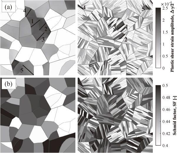
(a) Plastic shear strain amplitude accumulated in the last simulated cycle and (b) corresponding Schmid factor maps.
This result indicates that the plastic activity predicted by the current CP model is mainly governed by the Schmid law without any constraint on the slip direction related to the lath plane. Michiuchi et al.2) statistically compared the relationship between the Schmid factors of each slip system and the activated Burgers vectors of 56 martensite blocks after 20% tensile straining. They introduced a parameter defined as the difference between the highest Schmid factor for in-lath slip and the highest one for out-of-lath slip. A negative value indicates that out-of-lath slip should be preferentially activated based on the Schmid law. By comparing the crystal rotation predicted by Sachs and Taylor models with the experimentally measured one, it was found that half of the investigated blocks had a higher out-of-lath Schmid factor but deformed by in-lath slip. The simulations are therefore in contradiction with these experimental evidences as no distinction is made between in and out-of-lath slip activation. A solution to match these observations could have been to restrict out-of-lath slip and only allow the deformation of the two slip systems belonging to the lath plane.
The probability distributions of the plastic strain amplitude for the two models are depicted in Fig. 8. The distributions are particularly different for low and high strain amplitudes. In particular, a peak in the high-strain region was observed for the Packet model while it was not present in the Block model. This may lead to an overestimation of the actual plastic strain accumulated in the packet and therefore to a conservative estimation of the strength of the material. It was also noted from the distributions that the maximum plastic strain in each model is of the same order of magnitude. This is a direct consequence of the lack of size effect in the CP model. Size effect is generally considered in a CP model by introducing geometrically necessary dislocations (GND). The evolution of the density of GNDs is then related to the spatial gradient of the plastic deformation gradient tensor making the approach non-local.27) The introduction of a length-scale effect increases stresses at the grain scale while decreasing and redistributing the plastic strain in accordance with the Hall-Petch effect.27) Such effect is absent from the current CP model. Consequently, the plastic strain in Block models is most certainly overestimated. These observations are similar to that of Osipov et al.11) who showed in the case of bainitic steels, that the von Mises stress distribution exhibited different shapes depending on the studied configuration but similar maximum values.

Probability densities of the plastic shear strain amplitude accumulated in the last simulated cycle for the two models.
The study finally focuses on the estimation of the Tanaka-Mura FIP and on the predictive capabilities of the methodology for its evaluation. The location of the five PCPs with the highest Tanaka-Mura FIP are displayed on the microstructures in Fig. 7(a) and on additional microstructures in Fig. 9. Only the highest FIP per packet was considered since it is frequent to have several blocks with high FIP within a packet. In Packet models, cracks were predicted to initiate in packets with the highest plastic strain and on the longest PCP since the corresponding slip band accumulates more strain per cycle. In Block models, cracks initiated in blocks with the highest plastic strain only if the activated slip system belonged to the in-lath plane as the PCP would be the longest. Comparing one to one the location of the PCPs for the two models, it was noticed that the position and orientation of the PCP were very similar if the most activated in-lath slip system was the same in the two models. However, in cases where the activated slip system in Packet model did not correspond to the in-lath slip system, predictions were quite different. As explained in previous section, the CP model does not differentiate in and out-of-lath slips in term of preferential activation system. Nonetheless, by introducing a length-scale in the formulation of the FIP, the prediction of crack initiation becomes sensitive to microstructural features, especially the block morphology. In the absence of block boundaries, such sensitivity disappears as the PCP may extend through the packet width even though it corresponds to an out-of-lath slip system. Therefore, the inherent relationship between block elongation direction and its crystallographic orientation is lost.

Plastic shear strain amplitude accumulated in the last simulated cycle. The position of the five highest FIPs based on the Tanaka-Mura model per microstructure is represented.
To more quantitavely investigate the role of model hypotheses on the fatigue crack initiation, the distributions of the inverse FIP, which relates to the lowest crack initiation life according to the Tanaka-Mura model, were represented against the PCP length and the shear strain amplitude for the two models in Fig. 10. It was first observed that PCPs in Block models were bounded to about 0.25 mm while they could extend up to 0.5 mm in the absence of block boundaries in Packet models. Highest FIPs were found to be randomly scattered in the [0.1, 0.5] interval in Packet models while they were mostly found in largest PCPs in Block models. The orientations of the most critical slip plane per packet were also analyzed based on a stereographic projection of the slip plane normal as shown in Fig. 11. The orientations of the normal vectors of the critical plane where a crack was predicted to initiate are ranging from 30° to 60° with respect to the loading in the y-direction for the Block models while they are more scattered for the Packet models. Highest FIP values were preferentially found for slip normals orientated about 45° consistent with the fact they exhibit the highest Schmid factor.

Distribution of the inverse Tanaka-Mura FIP against the PCP length and shear strain amplitude for (a) Packet models and (b) Block models.

Stereographic projection in the plane of normal z of the normal vector of the slip plane with the most critical FIP in each packet for (a) Packet models and (b) Block models.
Based on these results, the application of the Tanaka-Mura model using a path-dependent approach correctly predicted cracks parallel to the lath interface and mostly oriented 45° from the loading direction in accordance with experimental observations.6) A criterion only based on local mechanical field such as the Dang-van28) or the Fatemi-Socie29) criterion would be unable to distinguish in-lath and out-of-lath slip system in term of probability of failure.
Some final considerations may be addressed as future works. The proposed study only dealt with two-dimensional aggregates with plane-strain assumption. Microstructures and fatigue cracks are inherently three-dimensional and simulating 3D polycrystals should provide additional information. In the case of lath martensite, the proposed tessellation framework can be transposed to 3D with the usage of flat ellipsoids for the description of blocks.
The paper has proposed a numerical method for the modeling of two-dimensional lath martensitic microstructures based on a multi-scale anisotropic tessellation allowing the reproduction of crystallographic and microstructural features inherent to lath martensite. The main purpose of the study was to evaluate the influence of the modeling hypotheses on the local mechanical fields and especially on the prediction of fatigue crack initiation using finite element simulations. Several concluding remarks can be made:
This study was partially supported by the Cross-ministerial Strategic Innovation Promotion Program (SIP) - Structural Materials for Innovation - unit D62 operated by The Cabinet Office, Japan.