Influence of Ingate Size on the Formation of Micro Shrinkage Pore in Gray Cast Iron
2019 Volume 60 Issue 5 Pages 777-784

Details
2019 Volume 60 Issue 5 Pages 777-784
In this paper, the origin of micro shrinkage pores in gray cast irons is revealed, and a solidification process for the iron is proposed. Gray cast irons, casted under various casting conditions, were examined in terms of density and optical microscopy microstructures of the irons. The amount of the added inoculation agent affects the size and the number of graphite particles per unit area, but does not affect the volume fraction of the graphite. The density of the iron was affected by the cross-sectional area of the ingate, regardless of the amount of the added inoculation agent. When the cross-sectional area of the ingate is larger than the appropriate size, the density of the iron decrease. The reason is the formation of micro shrinkage pores in the iron. The relationship between the solidification process and micro shrinkage pores of the gray cast iron was discussed based on the above experimental results. When the completion of the solidification in the ingate occurs before than that in the cavity, the molten metal cannot flow between the cavity and the runner by passing through the ingate. Therefore, the expansion due to the crystallization of the graphite is equal to the shrinkage due to the crystallization of the austenite at the eutectic solidification in the cavity. As a result, gray cast iron without micro shrinkage pores was obtained.
This Paper was Originally Published in Japanese in J. JFS 90 (2018) 443–449.

Fig. 7 Schematic illustration of solidification process for gray cast iron of hypoeutectic composition.
Cast iron is produced by a multistep process involving melting of the raw material, adjustment of the composition, and inoculation, followed by the pouring of the molten metal into the mold and solidification in the mold. During the solidification of cast iron, molten metal expands with the crystallization of graphite and shrinks with the crystallization of austenite. Because the extent of expansion is equivalent to that of shrinkage, overall shrinkage of the cast iron is not expected.1,2) In the case of hypoeutectic compositions, crystallization of the proeutectic austenite (dendrite) occurs as the temperature of the molten metal decreases, and followed by the simultaneous crystallization of graphite and austenite. Then, the eutectic cells are formed and the solidification process is completed. This solidification process applies to gray cast iron manufactured with hypoeutectic compositions. In the case of hypereutectic compositions, crystallization of graphite occurs as the temperature of the molten metal decreases. The amount of the crystallized graphite is increased with the increasing amount of the added silicon, because silicon acts as an accelerator in the crystallization of graphite. This solidification process is known to be applicable to spheroidal graphite cast iron, because the iron is produced with hypereutectic compositions and the silicon content of the iron is larger than that of the gray cast iron. For these reasons, the volumetric expansion of the spheroidal graphite iron, originated from the crystallization of graphite, is larger than that of the gray cast iron. Therefore, the extent of shrinkage in the spheroidal graphite cast iron is smaller than that in the gray cast iron. However, manufacturers believe that shrinkage is easier to form in spheroidal graphite cast iron than in gray cast iron, based on their practical experience. The exclusive phenomena discussed above have been motivated by numerous studies on the casting plan for spheroidal graphite cast iron,3) on the solidification process and formation of spheroidal graphite,4) and on the relationship between the carbon equivalent and volume change5,6) to explain the manufacturing phenomena associated with the shrinkage of cast iron materials. Several results from cast iron studies have also been discussed in review papers.1,7) While manufacturers seem to be resolving the phenomena related to the shrinkage by adjusting the carbon equivalent through the addition of carbon and silicon, such adjustments cannot resolve the abovementioned problem in an actual manufacturing process.
In this paper, the density and optical microstructure of hypoeutectic gray cast irons obtained by different inoculant amounts and casting plans (i.e., with different cross-sectional areas of the ingate), were investigated to interpret the phenomena of shrinkage in the cast iron production. A preliminary experiment shows that density measurements can detect whether micro shrinkage pores are formed frequently in iron or not at all. The calculated densities of the gray cast irons determined by the volume fractions of graphite and the micro shrinkage pore in the iron are shown in Fig. 1. The density of pearlite, which is the matrix of the iron, is 7.858 g·cm−3, calculated from the theoretical values of ferrite and cementite. Volume fractions of ferrite and cementite in pearlite were determined by the Fe–C phase diagram. The density of graphite, which is the literature value of 2.267 g·cm−3,8) was also applied. The size of test specimen and the measuring instruments for the density measurement were selected in order to detect the difference of about 0.25 vol% in the micro shrinkage pore in the test specimen.
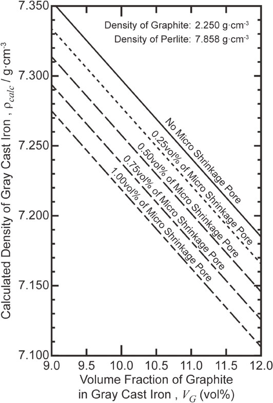
Density of gray cast iron calculated from volume fractions of graphite and micro shrinkage pores.
Based on the results obtained from these investigations, the formation factor of the micro shrinkage pores in hypoeutectic gray cast iron was explained and a solidification model of the iron was proposed. The reason why manufacturing problems related to the micro shrinkage pores of hypoeutectic gray cast irons are less than those of spheroidal graphite cast irons was discussed.
It is well known that the chemical compositions of cast irons significantly affect the manufacturing problems related to the shrinkage of cast iron. Therefore, hypoeutectic gray cast iron was obtained from the same molten metal with a combination of inoculant amounts and casting plans (i.e., with different cross-sectional areas of the ingate), as described in the following.
The chemical compositions of the source molten metal, which are determined by an optical emission spectrometer (Thermo Fisher Scientific K. K., ARL3460), and the nominal chemical compositions of the inoculant agent are presented in Tables 1 and 2, respectively. The amount of the added inoculant agents to the source molten metal were 0.15 mass% and 0.30 mass%.


An image of the test material taken from the mold and its dimensions are shown in Fig. 2. The test materials were obtained from a cylindrical cavity with a diameter of 80 mm and height of 30 mm. The length and width of the ingate for pouring molten metal into the cavity were both 10 mm. Three types of ingates with heights of 1.5 mm, 3.0 mm, and 6.0 mm were used in this study. Consequently, the cross-sectional areas of the ingate for these molds, which were produced by the process of injecting carbon dioxide gas, were 15 mm2, 30 mm2 and 60 mm2, respectively.

Shape and dimensions of as-casted material sample after breaking of casting mold.
The test specimens for the density measurement with a diameter of 72 mm and a height of 27 mm were machined from the casted materials. The mass of the specimen was measured using an electronic scale (A&D Co. Ltd., FX-3000i; capacity 3100 g; readability 0.01 g). The volume of the specimens was calculated from their diameter and height, measured by a micrometer. The density of the specimen was calculated from the measured mass and volume of the specimen. Furthermore, internal defects in the specimen were not detected by ultrasonic testing.
2.3 Observation of the optical microstructureThe number of graphite, the shapes of graphite, and the micro shrinkage pores were observed using an optical microscope (Olympus Co., PEM3). The number of graphite per unit area and the diameter of the graphite was approximated by an equivalent circle (nearly equal to the length of graphite particle), and the area rate of graphite were obtained by microscope images using the image analysis software (INOTECH Co., Model: QuickGrain VideoPro). The observed surface was mechanically mirror polished.
The relationships between the density and the cross-sectional area of the ingate for adding different amounts of inoculant agent are shown in Fig. 3. For the addition of 0.15 mass%, the density slightly decreases with the increasing cross-sectional area of the ingate. However, for the addition of 0.30 mass%, while the highest value obtained when adding this amount of inoculant agent was found for the cross-sectional area of the ingate of 15 mm2, the density quadratically decreases with the increasing cross-sectional area of the ingate. The lowest value of the density was obtained in the cross-sectional area of 60 mm2, with the addition of 0.3 mass%.

Relation between density and cross-sectional area of ingate.
Figure 4 shows the results of the image analysis for microstructures of the irons casted into the mold with 15 mm2 and 60 mm2 cross-sectional areas of the ingate. When the cross-sectional area of ingate was the same, the number of graphite particles per unit area was higher, and the average value of the equilibrium diameter of graphite was smaller in the iron with a 0.30 mass% addition of inoculant agent than in that with a 0.15 mass% addition of inoculant agent. As it is clearly shown in Fig. 3, the cross-sectional area of the ingate significantly affects the density of the irons, which were casted under the 0.30 mass% addition of inoculant agent. Thus, the optical microstructures of these irons were observed. For the iron casted under the cross-sectional area of the ingate of 15 mm2, a pearlite structure with no micro shrinkage pore was obtained, as shown in Fig. 5. However, a typical contrast, which is difficult to decide whether it is a micro shrinkage pore or not, was also observed as indicated by the arrows. While for the iron, casted under the cross-sectional area of the ingate of 60 mm2, a typical contrast, similar to the contrast indicated in Fig. 5, was observed as shown in Fig. 6. Moreover, micro shrinkage pores were dispersed in the iron. The combination of the addition of inoculant agent and the cross-sectional area of the ingate resulted in the difference of densities in the iron, because it affected the morphologies of the graphite and the formation of the micro shrinkage pore.

Typical results of image analysis for gray cast irons casted under various conditions.

Optical microstructure of gray cast iron added with 0.3 mass% inoculant agent (ingate size: 10 mm × 1.5 mm = 15 mm2). The arrow shows the typical contrast, for which it is difficult to decide whether it is micro shrinkage pore or not.

Optical microstructures of gray cast iron added with 0.3 mass% inoculant agent (ingate size: 10 mm × 6.0 mm = 60 mm2). The arrow shows the typical contrast, for which it is difficult to decide whether it is micro shrinkage pore or not. (a) Low magnification image observed at central region of cavity. (b) Enlargement of framed area b in (a). Micro shrinkage pore was observed. (c) Low magnification image observed at peripheral region of cavity.
The inoculation has been reported to facilitate the nucleation of graphite,9) and it is assumed that the increase of the amount of the added inoculant leads to the fine graphite particles with increased number. In this study, results supporting the above were obtained, as shown in Fig. 4.
The value of the carbon equivalent is varied according to the value of silicon, contained in the inoculant agent. Generally, the carbon equivalent (mass%CE) is calculated from the amount of carbon (mass%C) and silicon (mass%Si) according to the following equation.10)
| \begin{equation} \text{mass%CE} = \text{mass%C} + \frac{1}{3}\text{mass%Si} \end{equation} | (1) |
In a study a theory was established that the volume fraction of the graphite varies with the carbon equivalent,11) and the density of the cast iron is affected by the carbon equivalent, that is to say the amount of the added inoculant agent. The tested gray cast iron is produced from the same molten metal, as explained in Section 2.1, so that the carbon equivalent does not change, when the amounts of added inoculant agent are equal. For these reasons, the graphite volume fraction should not change, that is to say the density of the cast iron should not change, when the amounts of added inoculant agent are equal.
It is clear that the carbon and silicon content in the molten metal are higher than those in the original molten metal due to the addition of the inoculant agent. For a 0.15 mass% addition of the inoculant agent, the carbon and silicon contents in the molten metal were 3.455 mass%C and 2.299 mass%Si. While for a 0.3 mass% addition of the inoculant agent, these values were 3.450 mass%C and 2.408 mass%Si. The values of the carbon equivalent were calculated by using these carbon and silicon contents based on eq. (1). As a consequence, the values were 4.22 and 4.25 mass%CE with 0.15 and 0.3 mass% addition of inoculant agent, respectively. Thus, it is evident that the addition of the inoculant agent does not lead to a sufficiently high value of the carbon equivalent, which can affect the volume fraction of the graphite.
Although the addition of the inoculant agent does not affect the volume fraction of the carbon particles in the iron, it was found that an additional amount of inoculant agent affected the density of the iron casted with the same cross-sectional area of the ingate. The graphite particles were refined with the increase of the amount of the added inoculant agent (see Fig. 4). Moreover, it is reported that the graphite particles act as a nucleation site for the eutectic cell.7) Therefore, the refinement of the graphite particles, due to the increase of the amount of added inoculant agent results in the refinement of the eutectic cell. The gap between the dendrite and the eutectic cell increases with the decreasing size of the eutectic cell, such that, the unsolidified molten metal can flow easily near the eutectic temperature. Consequently, the addition of inoculant agent affects the fluidity of the molten metal, and leads to the formation of micro shrinkage pores. These phenomena result in the decrease of density of the gray cast iron.
3.3 Effects of cross-sectional area of the ingate on the densityIt is generally accepted that the variation of the density of the cast iron is due to the presence or absence of the micro shrinkage pores and the volume fraction of the graphite. As mentioned in Section 3.2, in this study the volume fraction of the graphite cannot affect the density of the iron. Because the value of the carbon equivalent is nearly equal for each of the irons tested. Therefore, the densities of the irons in this study were affected by the micro shrinkage pores, formed during the casting process. As these micro shrinkage pores are formed in the final solidification step of the casting process, they are considered to be located at the eutectic cell boundaries.
The results shown in Fig. 3 indicate that the density is increased by decreasing the cross-sectional area of the ingate. This relation is not related to the addition of inoculant agent. Consequently, the amount of the micro shrinkage pores is expected to decrease by decreasing the cross-sectional area of the ingate. This can be considered as follows. When using the mold with a smaller cross-sectional area of the ingate, the molten metal in the ingate is completely solidified before the complete solidification of the molten metal in the cavity. This phenomenon prevents the molten metal from flowing between the cavity and the runner channel (in this study, the runner channel means the pathway between the inlet and the cavity). The dendrite is crystallized at the start of solidification in the cavity. Eutectic cells are formed in the cavity together with the crystallization of both austenite and graphite when the temperature of the molten metal reaches the eutectic temperature or below. Because the solidification in the ingate is already completed at this point, the cubical expansion, caused by the crystallization of the graphite, cannot discharge the unsolidified metal from the cavity to the runner channel. At the same time that the cubical expansion occurs, the cubical shrinkage, caused by the crystallization of the austenite, occurs at the unsolidified region in the cavity. This results in a cast iron without micro shrinkage pores, because the cubical expansion balances with the cubical shrinkage.
When using a mold with a larger cross-sectional area of the ingate, the time required for complete solidification in the ingate is longer than that required when using a mold with a smaller cross-sectional area of the ingate. Crystallization of the proeutectic austenite (dendrite) occurs at the start of solidification in the cavity. When the temperature of the molten metal reaches the eutectic temperature, the unsolidified molten metal in the cavity is able to flow into the runner channel due to the cubical expansion caused by the crystallization of the graphite in the cavity. At the same time, cubical shrinkage occurs in the cavity, caused by the crystallization of the austenite. When the cubical expansion does not balance the cubical shrinkage, micro shrinkage pores are formed at the boundaries of the eutectic cells in the cavity (shown in Fig. 6). The formation of micro shrinkage pores resulted in the decrease in the density of the cavity. Hence, the variation in the cross-sectional area of the ingate results in the phenomenon of whether molten metal flows between the cavity and the runner channel or not. This results in a cast iron with or without micro shrinkage pores.
3.4 Gray cast iron solidification modelThe solidification model for hypoeutectic gray cast iron is considered based on the above mentioned experimental results, as presented in Fig. 7.

Schematic illustration of solidification process for gray cast iron of hypoeutectic composition.
When the temperature of the molten metal reaches the liquidus line, the proeutectic austenite (dendrite) is crystallized. The dendrite grows with the decrease of the temperature. When the chemical composition and temperature of the unsolidified metal reach the eutectic point, graphite and austenite are crystallized and eutectic cells are formed. During this process, the volume of the molten metal shrinks with the decrease of the temperature until it reaches the liquidus line. The solidification shrinkage due to the crystallization of the dendrite occur at the temperature between the liquidus line and the eutectic isothermal line. While, beneath the eutectic point the shrinkage and expansion, caused by the crystallization of austenite and graphite, occur.
The eutectic solidification of a gray cast iron occurs simultaneously in all unsolidified regions surrounded by dendrite. In other words, the simultaneous events of the shrinkage and expansion, due to the crystallization of austenite and graphite, results in the formation of micro shrinkage pores at the eutectic cell boundaries, unless the amount of the shrinkage and the expansion are in balance. Furthermore, this phenomenon is not affected by the shape of the cavity. Specifically, the micro shrinkage pores are formed at the eutectic cell boundaries under the refinement conditions of the graphite and eutectic cell.
3.5 Discussion of a casting plan based on the solidification modelFor the addition of inoculant agent of 0.30 mass%, an increase of the cross-sectional area of the ingate led to the decrease of the density of the iron. When using a mold with a larger cross-sectional area of the ingate, the time required for complete solidification in the ingate is longer than that required when using a mold with a smaller cross-sectional area of the ingate, as described in section 3.3. This leads to the decrease of the density, i.e., the formation of the micro shrinkage pores at boundaries of the eutectic cells in the cavity. This result suggests that the final solidification points in gray cast iron are independent of the shape of the cavity. This is an important issue in the casting plan of gray cast irons.
In the actual manufacturing of gray cast irons of hypoeutectic compositions produced by greensand casting, the final solidification point is intentionally designed in the mold, based on empirical knowledge. For this casting plan, a liquid shrinkage is observed immediately after the pouring at the top of the pouring cup and/or the riser, which are higher than the cavity. When the temperature of the molten metal reaches to the eutectic temperature, the shrinkage and expansion, caused by the crystallization of austenite and graphite, occur, and then the solidification process is completed. If the unsolidified metal cannot flow out of the cavity, micro shrinkage pores are not formed in the cavity. The solidification sequence is determined by the casting plan based on empirical knowledge. The unsolidified metal flow at the final solidification of the molten metal is controlled by the empirical casting plan, which sets the runner shape, the cross-sectional area of the ingate, etc. Specifically, a smaller cross-sectional area of the ingate, blocking the molten metal flowing between the cavity and the runner channel at an early stage after the pouring, results a cast iron without micro shrinkage pores. This is a reasonable technique for the casting plan of gray cast irons.
For spheroidal graphite cast irons, irons with no micro shrinkage pores can be obtained by eliminating the riser and using a smaller cross-sectional area of the ingate. Several conditions are required to realize this effect: a sufficiently rigid mold, and appropriate pouring temperature and molten metal composition. Proeutectic austenite (dendrite) is not obtained in the casting process for spheroidal graphite cast irons, because the chemical composition of these irons is eutectic composition. Therefore, austenite is crystallized around the crystallized spheroidal graphite and then the eutectic cells are formed. While, for the gray cast irons, the primary crystal of austenite, crystallized as the dendrite, are obtained at the early solidification stage, because the chemical composition of the irons is a hypoeutectic composition. Furthermore, when the temperature of the unsolidified metal reaches the eutectic isothermal line, the eutectic cells, composed by the eutectic crystallized austenite and graphite, are obtained from the unsolidified metal, which is a high carbon composition due to the crystallization of the dendrite. Thus, the difference between the solidification process of the gray cast irons and that of the spheroidal graphite irons, i.e., the presence or absence of the dendrite and the morphology of the eutectic cell, is the fundamental origin of the specific phenomena observed in cast iron manufacturing.
The densities and optical microstructures of hypoeutectic gray cast irons obtained by different additions of inoculant agent and cross-sectional areas of the ingate were investigated. Based on the experimental results, the origin of the micro shrinkage pores was explained and the solidification model for hypoeutectic gray cast iron was proposed. The reason why manufacturing problems related to the micro shrinkage pores of hypoeutectic gray cast irons are less than that observed in spheroidal graphite cast irons was clarified. The results can be summarized as follows.