Abstract
In this study, fatigue crack propagation testing on underfill resins with different filler content and finite element method (FEM) analysis were carried out to investigate the effects of filler content on fatigue crack propagation rate. The fatigue crack propagation rate of the underfill resin decreased with increasing filler content. FEM analysis clearly showed that fillers constrain the deformation of resin around them, which leads to inhibition of the amount of crack opening and a decrease in the energy release rate surrounding a crack tip. Since the amount of crack opening decreased with increasing filler content, it is conceivable that the decreased fatigue crack propagation rate can be attributed to a decrease in the amount of crack opening. The constraint on deformation of the base resin implies an increase in macroscopic static strength, and thus the resistance to fatigue crack propagation correlates with static strength.
1. Introduction
In high-density semiconductor packaging, the encapsulation technology with epoxy resin referred to as underfill resin is indispensable because the semiconductor die is bonded to the substrate by micro-solder bumps. It is known that fatigue cracks grow in the underfill resin due to cyclic thermal and mechanical stresses during use, which causes fracture of interconnections.1) Consequently, there is a need to develop superior underfill resins in terms of resistance to fatigue crack propagation. Given that silica filler is added to underfill resin, the influence of filler addition on the fracture strength of epoxy resin has been studied experimentally. It has been reported that fracture toughness Kc increases with increasing filler content and also increases with decreasing filler size.2–5) In addition, Kc is reported to increase with increasing filler size.6,7) However, another study found that the filler size does not affect Kc.8) With regard to fatigue crack growth characteristics, experimental evidence has been reported that the fatigue crack growth rate decreases with increasing filler content, and the lower limit of the stress intensity factor range increases with increasing filler content.9)
As the mechanism of these fracture strength improvements, crack deflection with filler addition has been reported, mainly through observations of fracture surfaces and crack propagation paths.2,6,10) However, the explanation of the mechanisms from the viewpoint of fracture mechanics is insufficient. In addition, since microscopic deflection of a crack does not generally affect the fatigue crack propagation rate of homogeneous materials, it is an open question whether microscopic deflection is the main cause of the decrease in the rate of fatigue crack propagation. Elucidation of the influence of filler on the fatigue crack growth rate of epoxy resin is important for the reliability design of underfill materials.
Therefore, in this study, the effects of silica filler addition with various ratios on the fatigue crack propagation rate in epoxy resin as an underfill were investigated via fatigue crack propagation testing and the finite element method (FEM).
2. Experimental Procedure
2.1 Specimens
The resin was bisphenol F-type epoxy resin hardened with an amine hardening agent. A silica filler with a spherical grain of average diameter of 0.5 µm that was surface-treated with a silane coupling agent was added to the resin. Three types of underfill resins with different silica contents were prepared in this study. The silica content was 26.0 vol.% (hereafter vol. is omitted), 34.4%, and 43.9%. A filler-free underfill resin was also used as reference. Figure 1 shows the initial microstructures of these underfill resins. A miniature flat plate with a single notch (single-edge notched) as shown in Fig. 2 was used for fatigue testing. The notch was introduced to each specimen using an ultrasonic cutter.
2.2 Fatigue crack propagation test
A mechanical testing machine equipped with a piezo actuator having a displacement enlargement mechanism (LMH207-20: Saginomiya Seisakusho) as shown in Fig. 3 was used for fatigue crack propagation testing. Force-controlled fatigue tests with constant amplitude sinusoidal load were performed. The test temperature was 298 K, the stress ratio was 0, and the frequency was 2 Hz. Fatigue crack lengths were recorded by a microscope video camera installed on the upper part of the test machine and measured at each prescribed number of cycles.
In the study, the fatigue crack propagation rate was evaluated using stress intensity factor K, which is a parameter of linear fracture mechanics, and was calculated using eq. (1),11)
| \begin{equation}
K = Y\sigma \sqrt{\pi a}
\end{equation}
| (1) |
where
Y is the geometrical parameter, σ is the stress, and
a is the crack length. When a crack is negligibly small compared with the width of the plate, the crack tip is not influenced by the external environment and the geometrical parameter can be defined as
Y = 1 in
eq. (1).
If the crack size is not negligible compared with the width of the plate, compensation is necessary because the external boundary affects the crack tip. For the specimen geometry in this study, eq. (2) represents the geometrical parameter Y,12)
| \begin{align}
Y &= \sqrt{\frac{W}{\pi a}} \times \frac{\sqrt{2\tan \cfrac{\pi a}{2W}}}{\cos \cfrac{\pi a}{2W}}\\
&\quad\times \left[0.752 + 2.02\left(\frac{a}{W}\right) + 0.37\left(1 - \sin \frac{\pi a}{2W}\right)^{3}\right]
\end{align}
| (2) |
where
W is the width of the specimen. The fatigue crack propagation rate
da/
dN is determined by the polynomial method with seven contiguous points, as recommended by the Japanese Industrial Standards.
2.3 Crack propagation analysis by FEM
In order to investigate the effects of filler additions on fatigue crack propagation, crack propagation analysis using FEM was also performed. Figure 4 shows the FEM model used for the analysis. The FEM model was a two-dimensional model, and the dimensions of the specimen were made smaller while maintaining the aspect ratio in order to reduce the analysis scale. The filler content in the FEM models was 26.0% and 43.9%. The differences in filler content were reproduced using the interparticle distance of the filler in the FEM models. Table 1 shows the distance between filler in the model created. The distance between filler ls was calculated by eq. (3),13)
| \begin{equation}
l_{\text{s}} = \sqrt{\frac{\pi}{6V_{\text{p}}}\frac{\overline{d_{\text{p}}{}^{3}}}{\bar{d}_{\text{p}}}}
\end{equation}
| (3) |
where
Vp is the volume fraction,
$\bar{d}_{\text{p}}$ is the average particle diameter, and
$\overline{d_{\text{p}}{}^{3}}$ is the average value of the particle diameter cubed. Although the filler particle size in the specimen was not uniform, the same size filler was used in the FEM model by assuming that the average particle size controls the crack propagation mechanism.

Table 1 Inter-filler distance for each model.
The initial crack length was found to be 7 µm for reproducing stable crack growth. From a preliminary analysis, the location of the initial crack tip was set to 0.125 µm in the x direction and 0.5 µm in the y direction from the center of the filler. Crack deflection was reproduced by propagating the crack from this position. The periphery of the crack tip was given a spider-web mesh for calculating fracture mechanics parameters. The element type was a quadrilateral eight-node generalized plane stress element with the thickness taken into consideration. In order to obtain r−0.5 singularity in the element, the crack tip was modeled by collapsing the elements at the crack tip to triangles and shifting their mid-side nodes to 1/4 of the edge. The general-purpose software ANSYS ver.18.1 was used for numerical simulation in this study.
The direction of crack propagation was calculated by using the maximum circumferential stress criterion. Circumferential stress σrθ and shear stress τrθ in the neighborhood of the crack tip under mixed modes I and II are expressed by eqs. (4) and (5), respectively:14)
| \begin{equation}
\sigma_{r\theta} = \frac{1}{\sqrt{2\pi r}}\cos \left(\frac{\theta}{2}\right)\left\{K_{\text{I}}\cos^{3}\left(\frac{\theta}{2}\right) - \frac{3}{2}K_{\text{II}}\sin \theta \right\}
\end{equation}
| (4) |
| \begin{equation}
\tau_{r\theta} = \frac{1}{2\sqrt{2\pi r}}\cos \left(\frac{\theta}{2}\right)\{K_{\text{I}}\sin \theta - K_{\text{II}}(3\cos \theta - 1)\}
\end{equation}
| (5) |
where
KI and
KII are the stress intensity factor of mode I and mode II, respectively, under the mixed mode loading, and
r is the distance from the crack tip. In the maximum circumferential stress criterion, the crack is assumed to propagate in the direction that satisfies τ
rθ = 0. For this reason, the angle θ
0 that satisfies τ
rθ = 0 was obtained.
Figure 5 shows an illustration of the settings of deflection angle and crack propagation length. After the analysis, the angle between the crack surface and the direction of crack propagation was calculated as the deflection angle θ
0. The deflection angle θ
0 was used to set the crack propagation direction and the crack propagation was advanced by the length of the radius of the spider-web mesh area. This process was repeated to investigate the effects of filler additions on crack propagation. When the crack came close to the filler and the spider-web mesh area and the filler overlapped, the radius of the spider-web mesh area was decreased.
Figure 6 shows a flowchart of the crack propagation analysis via FEM performed in this study.
For evaluation of the effects of filler addition on the fatigue crack propagation rate, the change in energy release rate $\mathcal{G}$ that accompanied crack propagation was used. Since $\mathcal{G}$ under mixed-mode loading in the plane stress problem can be expressed by eq. (6), $\mathcal{G}$ was calculated from eq. (6) after the calculation of the stress intensity factor of modes I and II,15)
| \begin{equation}
\mathcal{G} = \frac{K_{\text{I}}{}^{2}}{E} + \frac{K_{\text{II}}{}^{2}}{E} + \frac{K_{\text{III}}{}^{2}}{2\mu}
\end{equation}
| (6) |
where
KIII is the stress intensity factor of mode III under mixed-mode loading,
E is the Young’s modulus, and μ is the modulus of rigidity.
3. Results and Discussion
3.1 Fatigue crack propagation characteristics
Figure 7 shows the relationship between the fatigue crack propagation rates in the underfills evaluated in the study and the stress intensity factor range ΔK. In all specimens, the crack propagation rates in the stable growth area obeyed Paris’ law, represented by eq. (7),
| \begin{equation}
\frac{da}{dN} = C\Delta K^{m}
\end{equation}
| (7) |
where
C and
m are the material constants. The stress intensity factors of fast fracture area
KC are mostly equal to each other regardless of filler content. However, the range of the threshold stress intensity factor Δ
Kth was affected by filler content.
Table 2 shows values of
C and
m in
eq. (7) for individual specimens, as well as the threshold stress intensity factor range Δ
Kth. The material constants of
eq. (7) were determined by the least-squares method in the region of stable crack growth. As the filler content increased, the fatigue crack propagation rate decreased and the threshold value of fatigue crack propagation Δ
Kth increased. An increase in the amount of filler addition had the effect of inhibiting fatigue crack propagation.
Figure 8 shows observation results of the fatigue crack propagation path of each specimen.
Figure 8 indicates that in the filler-free resin, the fatigue crack grew linearly, whereas in the specimens with added filler, the fatigue crack deflected away from the filler. Therefore, the high fracture toughness mechanisms involving crack deflection were firstly examined.
When a crack deflects macroscopically, the crack propagation mode becomes the mixed mode of mode I and mode II and the energy release rate at the crack tip decreases. Equations (8) to (10) below were used to calculate the energy release rate for the occurrence of a macroscopic deflection,10)
| \begin{equation}
\mathcal{G}(\theta_{0}) = \frac{(1 - \nu^{2})K_{1}{}^{2}}{E} + \frac{(1 - \nu^{2})K_{2}{}^{2}}{E}
\end{equation}
| (8) |
| \begin{equation}
K_{1} = \cos^{3}\left(\frac{\theta_{0}}{2}\right)K_{\text{a}}
\end{equation}
| (9) |
| \begin{equation}
K_{2} = \sin \left(\frac{\theta_{0}}{2}\right)\cos^{2}\left(\frac{\theta_{0}}{2}\right)K_{\text{a}}
\end{equation}
| (10) |
where
Ka is the stress intensity factor on the assumption that the loading is only mode I, ν is Poisson’s ratio of the base material, and
E is Young’s modulus of the base material.
Table 3 shows the ratio of
$\mathcal{G}^{\text{N}}$ to
$\mathcal{G}(\theta _{0})$. Here,
$\mathcal{G}^{\text{N}}$ is the energy release rate when the crack propagates without deflection (θ
0 = 0). As the filler content increased, the deflection angle increased, thereby increasing
$\mathcal{G}^{\text{N}}/\mathcal{G}(\theta _{0})$. A larger
$\mathcal{G}^{\text{N}}/\mathcal{G}(\theta _{0})$ ratio indicates an increase in the amount of absorbable energy at the crack tip, which means that the crack deflection contributed to decreasing the rate of fatigue crack propagation.

Table 3 Deflection angle and energy release rate.
Although it has been reported that microscopic deflections observed in the study do not affect the fatigue crack propagation rate in homogeneous materials,16) it is an open question whether microscopic deflection of the crack is the main cause of decreased fatigue crack propagation rate. Figure 9 shows a schematic illustration of the microscopic deflection of a crack. When the crack that occurred from the bottom of a notch propagates, it propagates macroscopically at right angles to the stress axis, whereas microscopically it propagates while deflecting. When a is considerably larger than h, as in Fig. 9 (i.e., when an infinitesimal crack deflection occurs), the magnitude of tensile stress perpendicular to remote tensile stress at the crack tip is expressed by parameter $\skew3\bar{K}_{\text{I}}$ as in eq. (11).17)
| \begin{equation}
\skew3\bar{K}_{\text{I}} = \frac{1}{16}(8 + 9\cos \theta_{0} - \cos 3\theta_{0})
\end{equation}
| (11) |
shows
$\skew3\bar{K}_{\text{I}}$ for each deflection angle θ
0. There are mostly no differences in the values of
$\skew3\bar{K}_{\text{I}}$ until the deflection angle of 35 degrees. Even when the angle is increased to 55 degrees, the tensile stress at the crack tip is about 90% of that without deflection. In the fatigue crack propagation test performed in this study, the fatigue crack propagation rates differ more than 10 times by material. The contribution of microscopic deflection of the fatigue crack to the fatigue crack propagation rate is small.

Table 4 Tensile stress parameter for each deflection angle.
Figure 10 shows the fatigue crack propagation path in the FEM model for a filler content of 26.0%, as well as changes in $\mathcal{G}$, ΔKI, and ΔKII accompanied by crack propagation. The calculation results for $\mathcal{G}$ in the model without filler are also shown. The crack deflects away from the filler, which is consistent with the crack propagation path observed in the experiment. As the crack approaches the filler, $\mathcal{G}$ as the driving force for crack propagation decreases and the presence of the filler becomes a barrier to crack propagation in terms of energy. However, $\mathcal{G}$ started to decrease before the occurrence of the crack deflection, and thus the microscopic crack deflection was not dominant over the decrease in the fatigue crack propagation rate. Furthermore, the values of ΔKI and ΔKII differ from each other by at least one order of magnitude, and ΔKI is dominant over changes in $\mathcal{G}$ while the contribution of ΔKII is small. This indicates that the effects of filler addition on fatigue crack propagation are dominant over the decrease in the amount of crack opening, that is, in the increase in ΔKII caused by the crack deflection. In the area where the crack propagates away from the filler, $\mathcal{G}$ tends to increase again, in which case the value is equivalent to the maximum in that of the specimen without filler, and $\mathcal{G}$ substantially decreased around the filler. Thus, filler addition is effective for lowering $\mathcal{G}$.

Figure 11 shows the changes in $\mathcal{G}$ associated with crack propagation in the models for 43.9% filler and 26.0% filler. In the 43.9% filler model, in which the distance between fillers is short, $\mathcal{G}$ is small in all sections. As the filler content increases, $\mathcal{G}$ decreases as the driving force for crack propagation and the fatigue crack propagation rate is thought to decrease. This analysis result agrees qualitatively with the tendency of the experimental results shown in Fig. 7.
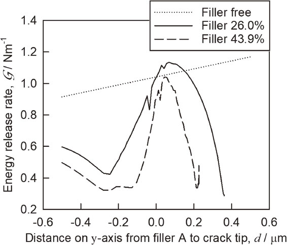
Figure 12 shows the contours of equivalent elastic strain around crack tips in the models with 26.0% filler and 43.9% filler. The equivalent elastic strain around the crack tip in the model with 43.9% filler is small and the area of small-scale yielding is also small. A decrease in equivalent elastic strain around the crack tip represents a decrease in the amount of crack opening since it is thought that decreasing $\mathcal{G}$ is due to a decrease in the amount of crack opening at the crack tip.

Figure 13 shows the crack opening displacement associated with crack propagation in each analysis model. The crack opening displacement was measured at a point 0.015 µm from the crack tip. Changes in $\mathcal{G}$ and changes in the crack opening displacement, both associated with crack propagation, showed a similar tendency to each other and the amount of crack opening decreased as the filler content increased. It has been reported that filler size affects the stress singularity at the crack tip.18) However, the decrease of $\mathcal{G}$ with increasing filler content in the present study is essentially caused by the decrease in the crack opening displacement due to the deformation constraint of the resin surrounding the crack by the addition of filler, as mentioned above.

The decrease in $\mathcal{G}$ has a great influence on the threshold limit ΔKth as well as the fatigue crack propagation rate. In particular, ΔKth is thought to have had a strong impact due to the filler constraints on local displacement, and ΔKth clearly increased with filler addition.
The constraint on deformation by filler addition has the meaning of increasing the deformation resistance, which is believed to be macroscopically related to strength parameters such as the elastic modulus. Figure 14 shows the relationships between the product of elastic modulus E and the 0.1% proof stress σ0.1 and material constant C and ΔKth in eq. (7). As static increase in the resistance to fatigue crack propagation by filler strength increases, C decreases and ΔKth increases. Thus, an addition is thought to be due to a decrease in the amount of crack opening around the filler caused by resin constraints. However, since it has been pointed out that the effect of this kind of microscopic structure is minimal on the area where a crack grows unstably, it does not seem that the value of fracture toughness Kc has been affected.
4. Conclusion
-
(1)
As the filler content increased, the resistance to fatigue crack propagation in underfill resin increased.
-
(2)
It was found from the results of crack propagation analysis by FEM that the deformation of surrounding resin is constrained by filler addition, resulting in a decrease in the amount of crack opening and leading to a decrease in the energy release rate surrounding filler.
-
(3)
Since the amount of crack opening decreases with increasing filler content, the fatigue crack propagation rate decreases with increasing filler content.
-
(4)
Since the constraint on resin deformation by filler addition is closely related to macroscopic static strength, an increase in static strength and an increase in the resistance to fatigue crack propagation—both associated with an increase in filler content—showed a good correlation with each other.
REFERENCES
- 1) R.R. Tummala: Fundamentals of Microsystems Packaging, (McGraw-Hill, New York, 2001) pp. 379–386.
- 2) T. Adachi, M. Osaki, W. Araki and S.C. Kwon: Acta Mater. 56 (2008) 2101–2109.
- 3) J. Spanoudakis and R.J. Young: J. Mater. Sci. 19 (1984) 473–486.
- 4) K.C. Jajam and H.V. Tippur: Int. J. Solids Struct. 49 (2012) 1127–1146.
- 5) R.P. Singh, M. Zhang and D. Chan: J. Mater. Sci. 37 (2002) 781–788.
- 6) M. Hussain, A. Nakahira, S. Nishijima and K. Niihara: Mater. Lett. 27 (1996) 21–25.
- 7) F.F. Lange and K.C. Radford: J. Mater. Sci. 6 (1971) 1197–1203.
- 8) A.C. Moloney and H.H. Kausch: J. Mater. Sci. 18 (1983) 208–216.
- 9) M.H. Kothmann, R. Zeiler, A. Rios de Anda, A. Bruckner and V. Altstadt: Polymer 60 (2015) 157–163.
- 10) K.T. Faber and A.G. Evans: Acta Metall. 31 (1983) 565–576.
- 11) H. Tada, P.C. Paris and G.R. Irwin: The Stress Analysis of Cracks Handbook, Third Ed., (John Wiley & Sons, Hoboken, 2000) pp. 46–53.
- 12) Test method for notch sensitivity and fatigue crack growth properties of metallic biomaterials, JIS T 0310, (2009).
- 13) Y. Yeh, H. Nakashima, H. Kurishita, S. Goto and H. Yoshinaga: J. Japan Inst. Metals 52 (1988) 1246–1254.
- 14) F. Erdogan and G.C. Sih: J. Basic Eng. 85 (1963) 519–527.
- 15) T.L. Anderson: Fracture Mechanics: Fundamentals and Applications, Fourth Ed., (CRC Press, Boca Raton, 2017) p. 62.
- 16) H. Nishitani: Trans. Jpn. Soc. Mech. Eng. 41 (1975) 1103–1111.
- 17) H. Nisitani, D. Chen and M. Isida: Trans. Jpn. Soc. Mech. Eng. A 50 (1984) 341–350.
- 18) A. Yaguchi, T. Terasaka and M. Kitano: J. Soc. Mater. Sci., Jpn. 49 (2000) 420–425.


