Abstract
This review confirms that the Love equation which connects the load on a rigid cone loaded normally on an elastic half-space, and its penetration into the half space, has been verified by several theoreticians. Furthermore, the predictions of the Love equation have been experimentally validated. It is argued here that a modification of the Love equation made about 20 years ago is incompatible with several theoretical treatments as well as with the expression for radial surface particle displacement outside the contact. Moreover, it is also shown that normal loading behaviour of a rigid cone on an elastic half-space cannot be likened to that of the normal loading behaviour of a rigid three-sided or a four-sided pyramid. Lastly, corrections are made to some important expressions given in a well cited paper by Sneddon (1965).
1. Introduction
Currently, in almost all analyses of experimental data obtained from experiments made with nanoindentation machines use is made of the solution of the normal loading of a rigid cone on an elastic half-space. Love1) was one of the first to provide such a solution. Love1) used a potential method, used earlier by Boussinesq2) for analyzing indentation situations in which the normal loading is applied on only a part of the elastic half-space.
In the formulations of the potential method, two approaches have been used. In one, the normal pressure distribution over the loaded area is given from which it is desired to determine the normal displacement of a particle in the half-space. In the other approach the normal displacement is prescribed and the normal pressure distribution over the loaded area is desired.
Boussinesq2) solved the cases for the normal loading of a rigid sphere and for the normal loading of a flat-ended cylindrical rigid die on an elastic half-space. Love1) solved the problem of the normal loading of a rigid cone on an elastic half-space with the axis of the cone being normal to the initially flat surface.
In Fig. 1 is shown the formulation of the cone indentation problem using a cylindrical polar coordinate system (r, θ, z) with the axis of the rigid cone being along the z-axis and the positive direction of the z-axis being in the direction of the penetration of cone into the elastic solid, as shown. Young’s modulus and Poisson’s ratio of the elastic half-space are E and ν, respectively. The semi included angle of the cone is α and the depth of penetration of the vertex of the cone into the solid is h, as shown in Fig. 1.
Within the contact circle, surface particles originally on the plane, move normal to the plane, ending on the cone surface, as shown with arrowed solid lines in Fig. 1. From the vertex of the cone to the edge of contact at r = a, the rigid cone fits snugly into the elastic solid. Thus, the equation of the surface of the cone is
| \begin{equation}
z = h - r\,\mathit{cot}\,\alpha.
\end{equation}
| (1) |
Outside the contact, both the normal stress (σ
z(
r))
z=0 = 0 and the shear stress (σ
rz(
r))
z=0 = 0. These normal stress and shear stress values outside the contact along with
eq. (1) form the boundary conditions.
Love’s1) solution predicts relationships between various parameters, such as P, h, α, a, surface profile outside the contact, (uz(r))z=0, and radial displacement of surface particles (ur(r))z=0 both inside and outside the radius of contact. These predictions are given in Section 2. Love’s1) solution has been reproduced by a number of theoreticians, namely Harding and Sneddon,3) Galin,4) Lur’e,5) and Hill and Storåkers.6)
Predictions of Love’s solution have also been verified experimentally (see Section 3).
In nanoindentation studies loading/unloading with a 3-sided Berkovich pyramidal indenter is generally likened to that of an equivalent right circular cone. In Section 4 it is shown experimentally that the two cases cannot be likened to each other. Besides, it is argued that the two situations are fundamentally different from each other.
In 1999 Hay et al.7) noted that Love’s1) expression for surface particles’ displacements inside the contact lead to the problem of penetration of the elastic material into the rigid cone. In order to avoid interpenetration, Hay et al.7) modified Love’s1) solution; this modification has recently been shown to be incorrect8) (see Section 5).
Finally, in Section 6 some minor, but important, corrections are made in expressions for elastic normal loading on an elastic half-space with rigid conical and spherical indenters given in a very well cited paper by Sneddon.9)
2. Predictions of Love’s Solution
As stated in Section 1, Love’s1) solution gives expressions connecting the load P on the cone and its penetration h into the elastic half-space, and surface particles’ displacements both inside and outside the contact. Thus, P and h are connected by
| \begin{equation}
P = \frac{2}{\pi}\frac{E}{(1-\nu^{2})}h^{2}\,\mathit{tan}\,\propto,
\end{equation}
| (2) |
in which the various parameters, namely
E, ν, and α have been defined in the above.
Love’s1) expression for the surface profile is given by
| \begin{equation}
[u_{z}(r)]_{z=0} = \mathit{cot}\propto\left\{a\,\mathit{sin}^{-1}\left(\frac{a}{r}\right) + (r^{2} - a^{2})^{\frac{1}{2}} - r\right\},\quad \text{for $r>a$}
\end{equation}
| (3) |
in which [
uz(
r)]
z=0 is the normal surface displacement in the z-axis direction.
Love’s1) expressions for the displacement of surface particles are given in differential forms, which are not easy to use. Harding and Sneddon3) gave these expressions in an integrated form and they also stated that their expressions are exactly the same as those of Love,1) although the two sets are in different forms. This has been confirmed (see Ref. 8). So, instead of giving here Love’s1) expressions, we give below the expressions given by Harding and Sneddon.3) Harding and Sneddon’s3) expression for the radial displacement of surface particles within the contact radius is
| \begin{equation}
[u_{r}(r)]_{z=0} = \frac{1-2\nu}{4(1-\nu)}r\,\mathit{cot}\propto\left\{\mathit{ln}\cfrac{r/a}{1 + \left(1-\biggl(\cfrac{r}{a}\biggr)^{2}\right)^{\frac{1}{2}}} - \cfrac{\left\lceil 1 - \left(1 - \biggl(\cfrac{r}{a}\biggr)^{2}\right)^{\frac{1}{2}}\right\rceil}{\biggl(\cfrac{r}{a}\biggr)^{2}}\right\}\quad \text{for $\mathrm{r} < a$},
\end{equation}
| (4) |
where [
ur(
r)]
z=0 is the surface radial displacement. Note that when ν = 0.5, the radial displacement of surface particles in
eq. (4) will be zero.
Outside the radius of contact the radial displacement of surface particles, as given by Harding and Sneddon,3) is
| \begin{equation}
[u_{r}(r)]_{z=0} = -\frac{(1 - 2\nu)}{4(1 - \nu)}\frac{a^{2}\,\mathit{cot}\,\alpha}{r}.\quad (\text{for $r > a$})
\end{equation}
| (5) |
3. Experimental Verification of Love’s
Eqs. (2) and
(3)Although eq. (2) has been in existence for ∼80 years, only a limited number of experimental studies has been made to examine its validity. In these studies the test specimens were almost always made of rubber or rubber-like materials and the cones were made of steel or polymethyl methacrylate. Relevant results from these studies are summarised in Table 1.

Table 1 Summary of results from experimental studies by different researchers who normally loaded solid cones on blocks of rubber and rubber-like materials.
It is clear from column 4 of Table 1 that eq. (2) fits the experimental results well. However, in none of the studies referred to in Table 1 was the surface profile outside the contact examined. Therefore, more comprehensive investigations were made by Lim and Chaudhri.13) In these investigations, besides showing that when effectively rigid cones of included angles 90°, 120° and 136° were loaded normally on blocks of natural rubber, neoprene, and polydimethylsiloxane elastomer cured with different amounts of a curing agent the load versus displacement behaviour was well fitted by the Love eq. (2). The surface profile outside the contact was optically observed in situ and measured. The experimental set up used by Lim and Chaudhri13) is shown in Fig. 2.


A selected tungsten carbide cone was mounted on a compression/tension load cell of load range 0–20 N, which in turn was screwed on to the cross-head of a mechanical testing machine (Instron Ltd., USA, Model 1122). Two LVDTs (linear variable differential transformer sensor, also called linear variable displacement transducer) were screwed into a stiff bracket, which in turn was firmly screwed on to a 6 mm diameter tungsten carbide rod on one end of which a cone of an appropriate included angle was ground and polished with a 1 µm diamond paste. The test specimen was placed on the base of the mechanical testing machine.
The loading and unloading of the test sample was carried out by moving the cross-head downwards or upwards, respectively. The test specimens were blocks of rubber, neoprene and blocks of PDMS (1:10), PDMS (1:20), and PDMS (1:30). In the case of the blocks of the PDMS compositions, the penetration of the test cone into them could be observed optically at a high magnification with a ×7 zoom lens attached to a video camera, which gave an optical spatial resolution of 2 µm. Thus the entire loading and unloading process could be recorded photographically.
The outputs from the load cell and the displacement transducers were fed into a two-channel 50 MHz storage oscilloscope (Phillips model PM 97) and a continuous record of the indenter load versus indenter displacement data was made. In this experimental set up the errors in load and displacement measurements were 0.3% and 2%, respectively. Machine compliance was 1 × 10⁻⁸ mN−1. The indentation load used was in the range 0.16 to 1.9 N.
Experimental results showed that in all cases and for cones of included angles 90° to 136° Love eq. (2) fitted the results very well, as shown in Fig. 3.
To monitor the surface profile of the elastic surface outside the contact radius, indentations with cones were made on transparent rubbers, that is, the PDMS compositions, and in situ video graphs were made using back-lighting. In this configuration the surface profile was clearly observed, as can be seen in Fig. 4 when a 90° tungsten carbide cone was normally loaded on a block of PDMS (1:10) under a load of 1.5 N.
Measurements of the surface profile were made from the video graphs similar to the one shown in Fig. 4. A comparison of eq. (3) with experimental data for the case of a 136° tungsten carbide cone loading on a blocks of PDMS (1:10) and PDMS (1:20) is shown in Fig. 5.
We note from Fig. 5 that the experimentally measured data are well fitted by eq. (3) thus confirming again the validity of the Love1) solution.
4. Comparison of the Normal Loading Behaviour of a Rigid Right Circular Cone with That of a Vickers Indenter Shape Pyramid or a Berkovich Indenter Shape Pyramid on an Elastic Half-Space
Most experimental nanoindentation studies and some macroindentation studies are made using a diamond Berkovich indenter or a Vickers indenter. These indenters are of pyramidal shapes. The base of the former is an equilateral triangle, whereas that of the other is a square. In the analysis of the unloading load versus displacement curves after an elastic/plastic indentation, it is assumed that the unloading process is elastic, though recently Chaudhri16) has criticised this assumption. Moreover, it is also assumed by some workers that the unloading process for a pyramidal indenter can be likened to the elastic unloading behaviour of a right circular cone of an equivalent apical angle such that the area of cross section of the cone and the pyramidal indenter is the same when measured at the same distance along the indenter axis from apex of the conical or pyramidal indenter.
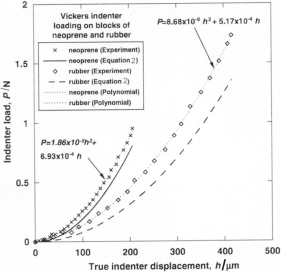
Lim and Chaudhri17) experimentally studied the P versus h behaviour when a tungsten carbide Vickers indenter was loaded normally on a block of PDMS (1:10). It was found that P did not vary parabolically with indentation depth, h, as is the case when a right circular cone is loaded on an elastic block. Indeed a polynomial equation fitted the experimental data, as shown in Fig. 6.
We have also found that when a Berkovich diamond indenter is loaded on a block of PDMS (1:10) using a nanoindentation machine (CSM Instruments, Switzerland) the P-h data were fitted by a polynomial equation (unpublished work).
These results using pyramidal indenters contradict several theoretical models,18–20) which rely on the self similarity of the indenters. Experiments have also shown that the contact perimeter when a Vickers indenter is loaded on a block of PDMS (1:10) does not lie on a single plane. On the other hand, in the case of the normal loading with a right circular cone the contact circle does lie on a single plane.
The theoretical models in Refs. 18 to 20 have ignored another important fact, which is that in the case of the normal loading with a rigid right circular cone, the projected contact area is a circle, but in the case of the normal loading with a Berkovich indenter the projected contact area is an equilateral triangle (see Fig. 7).
In the case of Fig. 7(a), the normal pressure distribution is radially symmetric, whereas in the case of Fig. 7(b) the normal pressure distribution cannot be radially symmetric. These differences are likely to cause a difference in the P-h behaviour between the normal loading with a cone and a Berkovich profile pyramid.
Therefore, following Way21) the surface particle displacement, for the same applied normal load, cannot be the same when the indenter is a right circular cone and when it is a pyramid.
5. An Incorrect Modification of the Love
Eq. (2)In 1999 Hay et al.7) modified eq. (2) so that interpenetration of the elastic material into the rigid cone would not occur. The modified equation is
| \begin{equation}
P = \gamma \frac{2}{\pi}\frac{E}{(1 - \nu^{2})}h^{2}\,\mathit{tan}\propto
\end{equation}
| (6) |
in which the modifying factor, γ, is a dimensionless factor dependent on the included angle of the cone and the Poisson’s ratio of the elastic half-space. As shown recently by Chaudhri,
8) a problem with
eq. (6) is that it gives an incorrect expression for the radial displacement of surface particles outside the contact circle.
According to Way,21) if on a circle of contact, with its centre at the origin, the total normal load is P, which produces a radially symmetric pressure distribution over the contact circle, then the surface radial displacement of a particle outside the contact circle and at a radial distance r from the origin will be the same as that when a point load P is applied normally at the origin. In the latter case, Way21) gives the radial surface displacement at a distance r from the origin as
| \begin{equation}
[u_{r}(r)]_{z=0} = -\frac{(1 - 2\nu)(1 + \nu)}{2\pi E}\frac{P}{r}.
\end{equation}
| (7) |
Love
1) eq. (2) for
r >
a also gives the same expression for the radial displacement of a surface particle at a distance
r from the centre of contact as
eq. (7). But the modification by Hay
et al.7) gives the radial displacement as
| \begin{equation}
[u_{r}(r)]_{z=0} = -\frac{(\mathbf{1} - \mathbf{2}\boldsymbol{{\nu}})(\mathbf{1} + \boldsymbol{{\nu}})}{\mathbf{2}\boldsymbol{{\pi}}\boldsymbol{{E}}}\frac{\boldsymbol{{P}}}{\boldsymbol{{r}}}\frac{\mathbf{1}}{\boldsymbol{{\gamma}}}
\end{equation}
| (8) |
The displacement given by
eq. (8) is smaller by a factor γ than the correct magnitude given by the well established
eq. (7) and is therefore incorrect. Thus we may conclude that the modification made by Hay
et al.7) is incorrect.
As regards the displacement of surface particles, both inside and outside the circle of contact, Chaudhri8) has proposed that as the load on the rigid cone is increased from zero, particles outside the contact move towards the axis of the cone. Once a particle reaches the surface of the cone, any further increase in the load on the cone will displace this particle along a path parallel to the z-axis, ending its journey on to the surface of the rigid cone, thus following the formulation of Love.1) A schematic diagram of the proposed displacement paths of surface particles is shown in Fig. 8.

It may be stated that although Fig. 8 is in agreement with the formulation proposed by Love,1) it contradicts Love’s1) solution as far as the radial displacement of surface particles within the contact circle is considered (i.e., eq. (4)). On the other hand, Fig. 8 is physically realistic because interpenetration of the elastic material into the rigid cone cannot occur. Careful experimental work is required to follow the displacement of particles from outside the contact towards the surface of the cone as the load on the conical indenter is gradually increased from zero.
6. Important Corrections to Expressions for the Normal Loading of a Rigid Cone and a Rigid Sphere on an Elastic Half-Space in Sneddon’s (1965) Paper
6.1 Rigid right circular cone of semi-included angle α
Although Harding and Sneddon3) derived a correct expression relating the load P on the cone and its penetration h into the elastic half-space when a rigid cone of a semi included angle α is loaded normally on an elastic half-space, in his 1965 paper Sneddon9) gave an incorrect expression (see eq. (6.5) of his paper). Sneddon’s9) eq. (6.5) is
| \begin{equation}
P = \frac{4G}{\pi(1 - \nu)}\mathit{cot}\,\alpha\cdot h^{2}.
\end{equation}
| (9) |
is incorrect because instead of
cot α in the numerator it should be
tan α. (It may also be noted that Giannakopoulos
20) gives the same incorrect expression in his
eq. (15))
Sneddon9) made an error by defining the cone profile as f(x) = ax tan α. The correct definition is f(x) = ax cot α. Using this correct definition of f(x) in Sneddon9) eq. (3.7), we get the total penetration depth, h, as
| \begin{equation}
h = \int_{0}^{1}\frac{f'(x)dx}{(1 - x^{2})^{1/2}}.
\end{equation}
| (10) |
Since
f′(
x) =
a cot α, the integral in
eq. (10) becomes
| \begin{equation}
h = \int_{0}^{1}\frac{a\,\mathit{cot}\,\alpha\,dx}{(1 - x^{2})^{1/2}} = \frac{\pi}{2}a\,\mathit{cot}\,\alpha.
\end{equation}
| (11) |
Expression in
eq. (11) is correct and it also agrees with the expression given by Love
1) p. 165.
In order to obtain the relationship between the load, P, on the cone and the total penetration, h, of the apex of the cone into the elastic half-space, we use the correct expression for f(x) in Sneddon9) (1965) eq. (4.3). Thus,
| \begin{equation*}
P = \frac{4Ga}{(1 - \nu)}\int_{0}^{1}\frac{x^{2}a\,\mathit{cot}\,\alpha\,dx}{(1 - x^{2})^{1/2}}
\end{equation*}
|
Or,
| \begin{equation}
P = \frac{4G_{s}}{(1 - \nu_{s})}a^{2}\,\mathit{cot}\,\alpha\int_{0}^{1}\frac{x^{2}}{(1 - x^{2})^{1/2}}\,dx
\end{equation}
| (12) |
The value of the definite integral in
eq. (12) is π/4. Therefore, we get
| \begin{equation}
P = \frac{4G}{(1 - \nu)}a^{2}\,\mathit{cot}\,\alpha\cdot \frac{\pi}{4}
\end{equation}
| (13) |
is in agreement with that given by Love
1) on p. 171.
Substituting the value of a from eq. (11) into eq. (13) and using G = E/2(1 + ν), we finally get the correct expression,
| \begin{equation}
P = \frac{2}{\pi}\frac{E}{(1 - \nu^{2})}h^{2}\,\mathit{tan}\,\alpha.
\end{equation}
| (14) |
It is not widely known that exact analytical expressions for the elastic loading of a rigid sphere on an elastic half space had been derived by Sneddon9) about half a century ago. One of these expressions allows the displacement, w0, of the sphere to be calculated accurately for large a/R values, where a and R are radii of contact and sphere, respectively. However, there is an error in the expression relating the load P, a, and R (see eq. (6.15) of Ref. 9). As stated in the above, this error does not appear to have been pointed out in the literature. The error is in the last term inside the curly brackets. Going through the algebra, we find that the correct expression is given by eq. (15). Here we have multiplied the last term in the curly brackets with 2. Thus,
| \begin{equation}
P = \frac{G}{(1 - \nu)}\left\{(a^{2} + R^{2})\,\mathit{ln}\frac{R + a}{R - a} - 2aR\right\},
\end{equation}
| (15) |
in which
G is the shear modulus (defined in the above) and the only restriction on
a is that it is less than
R.
Equation (15) is the same as eq. (16) of Segedin.
22)
7. Conclusions
It has been shown experimentally that when rigid cones of included angles 90°, 120°, and 136° are loaded normally on a number of rubber blocks, namely neoprene, a natural rubber composition, three different compositions of polydimethylsiloxane, the load versus cone penetration behaviour is well fitted by the Love equation (2). Moreover, when loading on transparent rubber blocks of polydimethylsiloxane, the surface profile has been shown to be according to the predictions of the Love equation (3). It has also been shown experimentally that the normal loading behaviour of a right circular cone cannot be likened to the normal loading behaviour of a three-sided or a four-sided pyramid. Theoretical arguments have been given why the two situations are different from each other. Finally, important corrections to theoretical expressions in a well-cited paper of Sneddon (1965) are made. It is hoped these corrections will be of some help to researchers of the nanoindentation community.
Acknowledgements
I would like to thank Professor Takahito Ohmura and the Organising Committee of the IIW6 for an invitation to participate in the international meeting.
REFERENCES
- 1) A.E. Love: Q. J. Math. 10 (1939) 161–175.
- 2) J. Boussinesq: Application des Potentials a l’Étude de l’Équilibre et du Mouvement des Solides Élastiques, (Gauthier-Vill ars, Paris, 1885).
- 3) J.W. Harding and I.N. Sneddon: Math. Proc. Cambridge 41 (1945) 16–26.
- 4) L.A. Galin: Contact Problems in the Theory of Elasticity, English translation ed. by I.N. Sneddon, (North Carolina State College, Department of Mathematics, Raleigh 1961).
- 5) A.L. Lur’e: Three-Dimensional Problems of the Theory of Elasticity (English Translation from Russian by D.B. McVean), ed. by J.R.M. Radok, (Interscience Publishers, New York, 1964) p. 284.
- 6) R. Hill and B. Storảkers: in Elasticity, ed. by G. Eason and R.W. Ogden, (Ellis Horwood Ltd., New York, 1990) pp. 199–209.
- 7) J.C. Hay, A. Bolshakov and G.M. Pharr: J. Mater. Res. 14 (1999) 2296–2305.
- 8) M.M. Chaudhri: Philos. Mag. Lett. 97 (2017) 343–349.
- 9) I.N. Sneddon: Int. J. Eng. Sci. 3 (1965) 47–57.
- 10) B.E. Sabey: Proc. Phys. Soc. 71 (1958) 979–988.
- 11) B.J. Briscoe, K.S. Sebastian and M.J. Adams: J. Phys. D 27 (1994) 1156–1162.
- 12) D. Vallet and M. Barquins: Int. J. Adhes. Adhesives 22 (2002) 41–46.
- 13) Y.Y. Lim and M.M. Chaudhri: Philos. Mag. 84 (2004) 2877–2903.
- 14) F. Schneider, T. Fellner, J. Wilde and U. Wallrabe: J. Micromech. Microeng. 18 (2008) 065008.
- 15) C.-E. Wu, K.-H. Lin and J.-Y. Juang: Tribol. Int. 97 (2016) 71–76.
- 16) M.M. Chaudhri: J. Appl. Phys. 124 (2018) 095107.
- 17) Y.Y. Lim and M.M. Chaudhri: Mech. Mater. 38 (2006) 1213–1228.
- 18) J.E. Barber and D.A. Billings: Int. J. Mech. Sci. 32 (1990) 991–997.
- 19) P.-L. Larsson, A.E. Giannakopoulos, E. Soderlund, D.J. Rowcliffe and R. Vestergaard: Int. J. Solids Struct. 33 (1996) 221–248.
- 20) A.E. Giannakopoulos: J. Mech. Phys. Solids 54 (2006) 1305–1332.
- 21) S. Way: J. Appl. Mech. 7 (1940) A-147–A-157.
- 22) C.M. Segedin: Mathematika 4 (1957) 156–161.