Preparation of Titanium Alloy/Bioactive Glass Composite for Biomedical Applications via Selective Laser Melting
2019 Volume 60 Issue 9 Pages 1779-1784

Details
2019 Volume 60 Issue 9 Pages 1779-1784
Selective laser melting (SLM) is widely used for the additive manufacturing (AM) of metal components, which can produce net shape complex geometries. Novel titanium alloy/bioactive glass composites were successfully fabricated via SLM method for biomedical applications. The fabricated composites contained a Ti5Si3 phase, which resulted from the reaction between the titanium alloy and the bioactive glass. The phase can improve the bonding strength between composite and bone. Additionally, the remained amorphous bioactive glass phase could improve bioactivity. The present study opens a new avenue for developing new titanium alloy/bioactive glass composites with optimal bioactivity and bonding strength with the bone.

Selective laser melting (SLM) is one of the powder-bed fusion methods that are widely used for the additive manufacturing (AM) of metal components.1) AM allows for the production of net shape complex geometries, which cannot be accomplished with standard manufacturing techniques such as casting or forming. There are many reports on the AM fabrication of Ti-based alloys.2) Ti–6Al–4V is widely used in biomaterials, because of its good biocompatibility and osteoconductivity.3,4) The reduction of the Young’s modulus of implant material is very important to prevent bone resorption caused by stress shielding.5) Our group developed a novel Ti–6Al–4V solid/powder composite with a tough hierarchical structure and a low Young’s modulus that can prevent stress shielding.6) Recently, a beta-type titanium alloy became an attractive biomedical implant material7) because its Young’s modulus is lower than that of Ti–6Al–4V.8) In addition, our group developed a beta-type titanium alloy with texture control in low modulus that could be used for the development of implants that suppress stress shielding.9) Bone tissue has an anisotropic structure that is strongly associated with collagen fibril orientation and the direction of the c-axis of bone apatite crystal.10) In our previous study, bone tissue orientation, rather than bone mass, was the dominant factor in the mechanical function of bone.11) Bone tissue orientation was determined by mechanical loading12–14) and osteoblast orientation.15–20) Novel biomedical implants that prevent stress shielding and recover bone tissue orientation can be developed by designing their net shape and crystallographic texture using the AM process.
Bioglass 45S5 introduced the concept of bioactive materials whereby the material provided chemical cues for enhancing metabolism and accelerating the healing of damaged bone.21,22) Xynos et al. reported that the dissolved silicate, calcium, and orthophosphate ions from Bioglass 45S5 stimulate human osteoblast proliferation by increasing the production of insulin-like growth factor II,23) and upregulate alkaline phosphatase and osteocalcin, which are parameters of osteoblast differentiation.24) Extensive studies have shown that the application of Bioglass 45S5 regenerates and repairs hard tissue such as bone and teeth.25) Recently, the effect of Bioglass 45S5 in angiogenesis,26) soft tissue regeneration,27) and wound healing28) has been studied. Day reported that the upregulation of vascular endothelial growth factor (VEGF) and basic fibroblast growth factor (bFGF) on fibroblasts was caused by the direct stimulation of the cells by Bioglass 45S5.29) In wound healing, Bioglass 45S5 enhanced the proliferation of fibroblasts and the growth of granulation tissue and upregulated bFGF and VEGF.30)
We aimed to create a novel metal/ceramic composite for biomedical applications using AM technology. Because of the potentially difficulty in controlling the texture of beta-Ti composite due to heterogeneous nucleation. Ti–6Al–4V, which have extensive application of biomedical field, was selected in this article. Additionally, Bioglass 45S5 was selected to enhance bone regeneration and angiogenesis. Bioglass 45S5 in the composite need to keep amorphous status due to maintain its excellent bioactivity. During the AM process the melts were quench, and can keep amorphous status of the glass compare with sintering process. Herein, we report on our fundamental investigation on the design of Ti–6Al–4V/Bioglass 45S5 composites for biomedical application using the SLM method and the evaluation of their microstructures.
Ti–6Al–4V powder, denoted by Ti64, was purchased from EOS (Titanium Ti64, 9011-0014; EOS GmbH Electro Optical Systems). Bioglass 45S5 (46.1SiO2·24.4Na2O·26.9CaO·2.6P2O5 in mol%, denoted by BG) was prepared by melt quenching. The glass batch was prepared by mixing SiO2 (99.0%), Na2CO3 (99.5%), CaCO3 (99.5%), MgO (99.0%), SrCO3 (98.0%), and NaH2PO4 (99.0%) (all reagents were purchased from Kishida Chemical Co.). The batch was melted in a platinum crucible at 1500°C for 30 min and quenched by pressing it with two stainless-steel plates. BG powder was obtained by grinding and sieving (35–75 µm). After coating the Ti64 and BG powders with an amorphous osmium layer using an osmium coater (Neoc CS, Meiwafosis Co. Ltd.), they were observed using field emission scanning electron microscopy (SEM, JSM-6500, JEOL). The diameter of the powders was obtained using ImageJ software (NIH) with the Feret diameter of the powders estimated from the SEM images.
The Ti64 and BG powders were mixed together for 2 h in a polyethylene container using a rotating mixer (ANZ-71D, Nitto Kagaku Co. Ltd.). The volume ratio of the BG powder in the two different powder mixtures was set to 10 and 30 vol%, and the mixtures were denoted by BGx (x = 10 or 30). The volumes of the Ti64 and BG powders were calculated from their densities of 4.43 and 2.72 g·cm−3, respectively. For the first trial of fabricate Ti64/BG composites, small batch of the mixtures were prepared, and the single layer composites were fabricated. The BGx powders were set in φ15-mm × 5-mm holes and the surface was flattened. Subsequently, the φ10-mm shape with a single scan layer was manufactured using an SLM apparatus (EOS M 290) equipped with a Yb fiber laser. The energy density E was set to 2.0 J·mm−2, the laser power P was 30 or 360 W, and the scanning pitch d was 0.1 mm. Scanning speeds (v, mm·s−1) were calculated using the following equation:
| \begin{equation} E = \frac{P}{v \times d} \end{equation} | (1) |
The BGx-P specimens were embedded in epoxy resin (EpoThin™, Buehler), sliced into approximately 3-mm-thick pieces, and mirror-polished on one side. The mirror-polished BGx-P samples were evaluated by X-ray diffractometry (XRD, X’pert PRO, Malvern Panalytical Ltd.) using Cu Kα radiation. Subsequently, after coating the samples with an amorphous osmium layer, they were evaluated using energy dispersive X-ray spectroscopy (EDS, JED-2300F, JEOL) for element mapping. The Ca-rich area in BG30-30 was analyzed using a microbeam X-ray diffraction system (D8 DISCOVER with GADDS, Bruker AXS) with Cu Kα radiation. An incident beam was collimated into a 50-µm-diameter spot.
SEM images of the Ti64 and BG powders and their diameter distributions are shown in Fig. 1(a)–(d). The average diameters of the Ti64 and BG powders were 10.23 ± 3.04 and 7.20 ± 2.49 µm, respectively. SEM images of the powder mixtures containing BG10 and BG30 are shown in Fig. 1(e), (f). The images confirm that the BG30 mixture had a greater amount of BG particles than the BG10 mixture. The powder mixtures were blended successfully, and the BG particles were well dispersed throughout the mixture without any aggregation. The powder-filling property and flowability of BG10 and BG30 into the holes in mold were suitable for the fabrication of the composites studied in this article.

SEM images and particle size distribution of (a, b) Ti64 and (c, d) BG powders. SEM images of (e) BG10 and (f) BG30 powder mixtures.
The shape of fabricate composites were circular without distortion, and the diameter was approximately 9.7 mm, which showed no significant difference between the samples. The thicknesses of the fabricated composites BG10-30, BG10-360, BG30-30, and BG30-360 were 0.53 ± 0.08, 0.50 ± 0.06, 0.64 ± 0.17, and 0.59 ± 0.12 mm, respectively. There was no significant difference among the thicknesses because the energy density introduced by the SLM apparatus was fixed at 2.0 J·mm−2. The XRD patterns of the composites are shown in Fig. 2. The XRD peaks of BG10-P and BG30-P correspond to Ti (ICCD card 44-1294) and Ti5Si3 (ICCD card 78-1429). The mole fractions of BG10 and BG30 for Ti:Si were 97.4:2.6 and 90.5:9.5, respectively. From the Ti–Si phase diagram,31) Si mole fractions of 2.6 and 9.5 can form the Ti5Si3 phase. In addition, the mixing enthalpies for Ti–Al, Ti–V, and Ti–Si were −30, −2, and −66 kJ·mol−1, respectively.32) Thus, the Si in BG and the Ti in Ti64 reacted to form the Ti5Si3 phase during the SLM process.

XRD patterns of BG10-P and BG30-P.
EDS mapping images for BG10-P and BG30-P are presented in Figs. 3 and 4, respectively. Figure 3 shows that the Ti64 area, i.e., the Ti- and Al-rich regions, and the BG area, i.e., the Ca- and O-rich regions, were distributed separately. Si in BG10-P was dispersed throughout the Ca- and O-rich regions because of the formation of the Ti5Si3 phase. BG10-30 and BG10-360 showed similar trends in element distribution. For BG30-360 (Fig. 4(g)–(l)), the Ti64 and BG areas were separate and Si was in in the BG area. Meanwhile, there was some unmelted Ti64 powder, and the BG area was located on the border between the melted and unmelted Ti64 area. BG30-30 (Fig. 4(a)–(f)) was drastically different from BG10-P and BG30-360. Si migrated into the Ti-rich region and there was a small amount of Ti in the Ca-rich region, whereas Al was concentrated in the Ca-rich region.

SEM images of (a) BG10-30 and (g) BG10-360 and EDS element mapping images of (b–f) BG10-30 and (h–l) BG10-360: (b, h) Ti, (c, i) Al, (d, j) Si, (e, k) Ca, and (f, l) O.
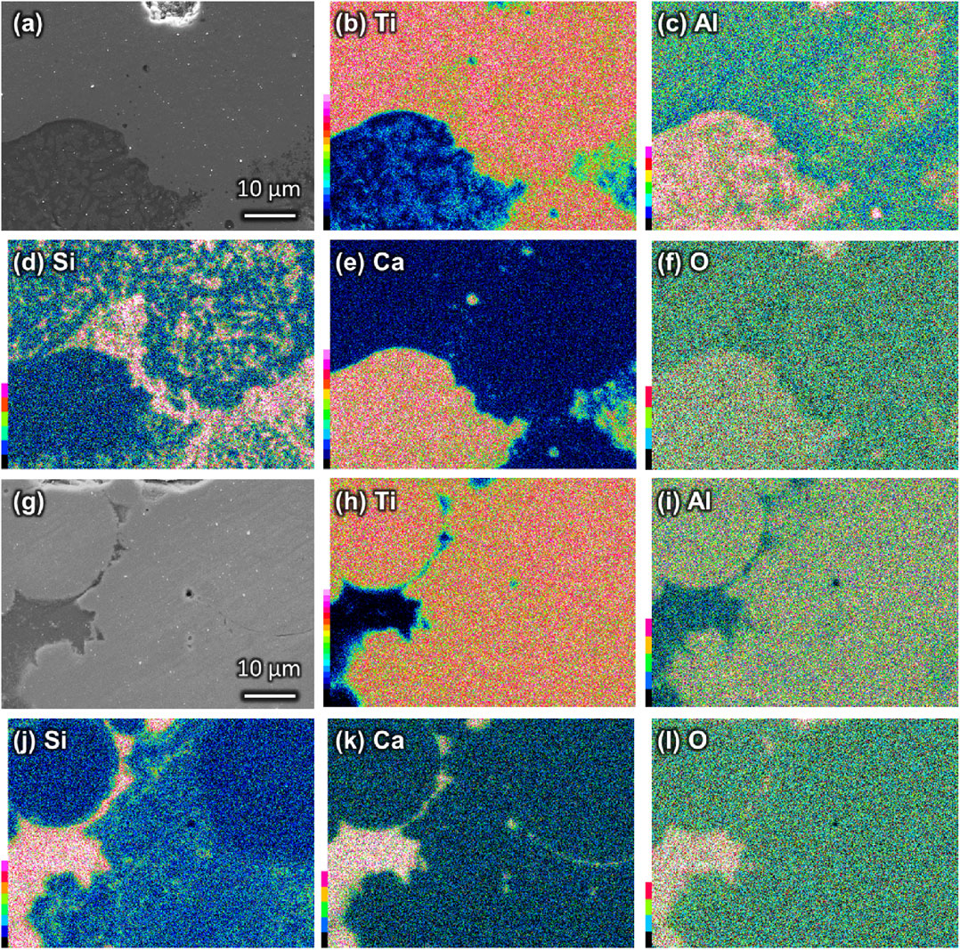
SEM images of (a) BG30-30 and (g) BG30-360 and EDS element mapping images of (b–f) BG30-30 and (h–l) BG30-360: (b, h) Ti, (c, i) Al, (d, j) Si, (e, k) Ca, and (f, l) O.
BG30-30 and BG30-360 were selected for a detailed analysis of their microstructures. Figure 5 shows the points analyzed and their spectra, and Table 1 presents the compositions of the analyzed points. Half of the composition at positions A and B in the Ca-rich region of BG30-30 (Fig. 5(a)) was oxygen (>50 atom%), which originated from BG. Figure 6 shows the microbeam XRD pattern of the Ca-rich region of BG30-30, with peaks corresponding to Ti, Ti5Si3, and CaTiO3 (ICCD card 75-0437). The atomic ratio of Ca:Ti:O for position B, which was the brighter part of the Ca-rich region of BG30-30, was 1.4:1.0:2.9. Hence, the crystalline phase of CaTiO3 was expected to form at position B. The EDS mapping image of Al in BG30-30 (Fig. 4(c)) shows the element concentrated at position A (Fig. 5(a)), as indicated by the darker areas in the Ca-rich region of BG30-30. In addition, Ca-, Al-, and O-related component peaks in the XRD result (Fig. 6) were not confirmed. Accordingly, the amorphous phase at position A was composed of the component CaO–Al2O3. Thus, the Ca-rich region in BG30-30 consisted of crystalline CaTiO3 and amorphous CaO–Al2O3 phases. Position C, which surrounds the Ca-rich region in BG30-30 (i.e., Ti-rich region), contained Ti5Si3 because the migration of Si was confirmed in EDS mapping image of Si in BG30-30 (Fig. 4(d)). Therefore, BG and Ti64 in BG30-30 reacted during the SLM process and formed the Ti5Si3, CaTiO3, and CaO–Al2O3 amorphous phases.

SEM images of (a) BG30-30 and (c) BG30-360 and (b, d) EDS spectra of points A–F in the SEM images.


Microbeam XRD pattern of BG30-30 at the center of the Ca-rich region.
The EDS mapping images of position D in BG30-360 (Fig. 4(j)–(l)) show a concentration of Si, Ca, and O, and the spectrum shows the peaks corresponding to those elements in BG (Fig. 5(d, D)). Accordingly, position D, which is the darker parts of BG30-360, defines the amorphous BG phases. The EDS mapping image of Si in BG30-360 (Fig. 4(j)) shows a small amount of the element in position E. The spectrum also shows the small peak corresponding to Si (Fig. 5(d, E)). Furthermore, the XRD result (Fig. 2) confirmed the Ti5Si3 peaks in BG30-360. The composition of position F in BG30-360 was similar to that of conventional Ti–6Al–4V, so the position was identified as unmelted powder. As a result, BG30-360 contained an amorphous BG phase, a small amount of the Ti5Si3 phase and some unmelted Ti64 powder.
BG10-P and BG30-30 contained amorphous phases; however, Si was not present in those phases owing to the reaction of Ti with Si to form the Ti5Si3 phase. BG10-P contained a smaller amount of BG than did BG30-P, that is, BG10-P had smaller volume of BG in the melt pool than did BG30-P. That is, BG in BG10-P can react easily with Ti64. Thus, almost all of the Si of the BG in BG10-P migrated into the Ti-rich region (Fig. 3(d), (j)) and reacted with Ti to form the Ti5Si3 phase. The scanning speed of BG30-30 was slower than that of BG30-360 because the energy density was fixed at 2.0 J·mm−2. Accordingly, the cooling speed of BG30-30 also was slower than that of BG30-360, which provided time for Si to migrate into the Ti-rich region. In addition, the CaTiO3 crystalline phase was induced because the amorphous phase in BG30-30 (i.e., Ca-rich region) could not be quenched. In contrast, BG30-360 contained an amorphous phase with Si because the composite was fabricated at a fast scanning speed, which induced quenching for the composite. Nevertheless, BG30-360 still contained the Ti5Si3 phase. These results show that we can fabricate a composite containing Ti64 and BG, but the SLM process needs further improvement. e.g. the microstructure of the composite to be designed as follows; Ti5Si3 is formed between Ti64 and BG area and the composition need to change graded for the mechanical property of the composites, and amorphous BG area need to keep preferentially during the process for the ion-releasability of the composites in order to promote the bone regeneration and angiogenesis.
The prepared composites formed the Ti5Si3 phase in all conditions because of the low enthalpy of mixing Ti and Si.32) Kitsugi et al.33) reported that the bonding strength of Ti5Si3 in an in vivo test was significantly greater than those of Ti–6Al–4V and Ti after 8 weeks of implantation. We expect that the Ti5Si3 phase that formed in the composites can improve the bonding strength of a material with bone. Notably, BG30-360 contained the amorphous BG phase, composed of Si and Ca, which can release therapeutic silicate and Ca2+ ions.23,24) Hence, BG30-360 could improve bioactivity and bonding strength via therapeutic ions and the Ti5Si3 phase, respectively.
Novel metal-ceramic composites for biomedical applications were fabricated via SLM. The composites contained a Ti5Si3 phase, which expected to improve the bonding strength of the composite with bone. The Ti5Si3 phase resulted from the reaction of Ti and Si from the Ti64 and BG powders, respectively, during the SLM process. In BG30-360, Si was in the amorphous phase because of the fast scanning speed used, which expected to improve bioactivity. These findings can lead to the fabrication of innovative titanium alloy/bioactive glass composites via the SLM process by controlling their microstructures for their use in hard and soft tissue regeneration.
This work was supported by the Council for Science, Technology and Innovation (CSTI), the Cross-Ministerial Strategic Innovation Promotion Program (SIP) Innovative Design/Manufacturing Technologies (Establishment and Validation of the base for 3D Design & Additive Manufacturing Standing on the Concepts of “Anisotropy” & “Customization”) from the New Energy and Industrial Technology Development Organization (NEDO). This work was also supported by Grants-in-Aid for Scientific Research from the Japan Society for the Promotion of Science (Grant Nos. JP18H05254 and JP17H06224), and a research grant for 2018 from The Japan Titanium Society.