1. Introduction
A combination of high strength and high ductility is crucial for many structural applications of metals and alloys. It is known that grain refinement is a well-known and attractive method to improve the strength of metallic materials. However, fine-grained materials are characterized by poor ductility. This effect, known as the strength-ductility trade-off, makes achieving good combinations of high strength and ductility rather challenging for the conventional homogeneous structural materials.1–5) A peculiar approach, to achieve a good combination of high strength without compromising in ductility, is a controlled and specific topological distribution of fine and coarse grains in the microstructure matrix, also called Harmonic Structure (HS).5) Such a novel microstructure can be induced in metals and alloys through controlled mechanical milling (MM) of spherical shaped powder particles, achieved by Plasma Rotating Electrode Process (PREP), followed by their sintering via Spark Plasma Sintering, (SPS), and Hot Isostatic Pressing (HIP), etc. In general, the mechanical milling induces Severe Plastic Deformation (SPD) at the outer surface of powder particles which leads to the formation of bimodal microstructured powder particles. Depending on the mechanical milling conditions, the outer deformed surface of powder particle contains SPD fine grains and inner core, in general, remains in an as-initial state of coarse grains.6,7) As a result, after sintering, a peculiar arrangement of ultra-fine grains (UFG) and coarse-grains (CG) can be obtained in sintered compacts. The interesting feature of the harmonic structure is its three-dimensional continuously connected network structure of ultra-fine grains (“Shell”) surrounding discretely distributed Coarse-grains (“Core”). For the conventional homogeneous structured materials (Homo), the plastic instability condition dσ/dε (σ: stress, ε: strain, dσ/dε: work hardening rate) satisfies at an early stage of the deformation. Therefore, increasing strength by grain refinement eventually results in a considerable ductility loss. In harmonic structured materials, it has been reported that the high work hardening extends to higher strain regions, as a result, initiation of plastic instability delays. Therefore, HS materials exhibit high tensile strength and uniform elongation.5,8–11) The outstanding mechanical properties of HS materials have already been confirmed in various metallic materials. It suggests that the improvement in mechanical properties by precise microstructure control, through the concept of harmonic structure design, is a universal method for metallic materials. However, the relationships between histologic elements and mechanical properties of harmonic structured materials have not been sufficiently elucidated. In this study, the authors have examined the role of the shell region on mechanical properties of harmonic structure designed pure Ni (FCC).
3. Experimental Result and Discussion
3.1 Structure of powder and sintered compacts
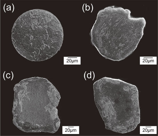
Figures 1 and 2 shows the representative SEM images of powder morphology, and cross-sectional microstructure, respectively, for the (a): initial powder particles, (b): 180 ks, (c): 360 ks and (d) 540 ks MM powder particles. The initial powder particles had a spherical shape with dendritic microstructure (Fig. 1(a)) which is expected to be evolved during PREP process involving fast cooling of liquid metal droplets during the flight. After mechanical milling, the powder particle surface was severely deformed, and the dendrites, at the outer surface, was not observed. The irregularity of surface significantly increased with increasing MM time, as shown in Fig. 1(b)–(d). Moreover, by comparing the powder cross-section structures, shown in Fig. 2, it was confirmed that the initial powder particle had throughout uniform microstructure, at the center and surface areas (Fig. 2(a)). On the other hand, after mechanical milling, the microstructure is significantly different at the outer surface area as compared to the center of powder particle (Fig. 2(b)–(d)). Also, the depth of plastic deformation increases with increasing MM time. It has already been shown that in the case of mechanical milling of pure Ti and stainless steel powders, nano-grain structures are formed on the plastically deformed surface area of the powder particles.16,17) In this study, the authors presume that the ultrafine-grain structures are formed on the pure Ni powder surface in the same way, and the region of such an ultrafine grain structure expands with MM time, as shown in Fig. 2(b)–(d). Figure 3 shows the Vickers microhardness results of the Ni MM powders separately, taken at the center and outer surface areas. It was observed that the hardness increased, at both the powder center and powder surface sections, with MM time. In the outer surface areas of powder particles, the hardening is mainly caused by grain refinement, while in the powder center, the work hardening occurs due to plastic deformation. After a long time MM, the hardness of the powder surface area reaches approximately the same level that of the center region. Therefore, it can be inferred that, after long time MM, grain refinement at surface and center regions reaches to a saturation level, and eventually, resulted in MM powder particles with approximately equal grain size at the powder surface and center regions. Figure 4 shows EBSD images (Band Contrast image + Grain Boundary image) of sintered compacts prepared from (a): MM 180 ks, (b): MM 360 ks, and (c): MM 540 ks MM powders. In the following text, the sintered compacts of (a), (b) and (c) is referred as “X”, “Y” and “Z”, respectively. The EBSD results confirm that the microstructure matrix consisted of both large size grains and comparatively finer grains. Moreover, it is also observed that the coarse-grained areas (“Core”) are surrounded by a continuously connected network of fine-grained areas (“Shell”). Therefore, after the sintering of MM powder Harmonic Structure was successfully developed in pure Ni. Figure 5 shows the grain size distribution measured by EBSD from the area that is four times as large as the structures shown in Figs. 4(a)–(c). It can be clearly seen that the grain size distribution of the sintered compacts becomes finer with increasing MM time. The separation of fine and coarse grains is clearly visible in the grain size distribution maps of the compacts prepared from longtime MM powders (Fig. 5(b), (c)). In this study, 8 µm is a threshold value which divides the fine grains from coarse grains. Table 3 shows the average grain size of “Shell” and “Core” and volume fraction of Shell, separately calculated from EBSD images of sintered compacts. It was confirmed that the grain size of “Shell” and “Core” decreased with increasing MM time whereas volume fraction of Shell significantly increases at the same time. As MM time increased, severe plastic deformation at the powder surface and deformation depth from the outer surface also increase. Therefore, the sintering of longtime MM powder ultimately leads to the Ni sintered compacts with approximately uniform fine-grained microstructure matrix as similar to the fine-grained conventional homogeneous microstructured Ni compact.8,12,13)


Table 3 Shell fraction and average grain size of harmonic structure compacts.
Figure 6 shows typical nominal stress-strain diagram obtained by tensile tests of (a): Harmonic Structured Ni compacts (HS, X–Z) and (b): Homogeneous Structure Ni compacts (Homo, A–D). For the HS Ni compacts, both Yield strength (YS) and Ultimate Tensile Strength (UTS) increased (Fig. 6(a)) with an increase in the volume fraction of “Shell”, as shown in Table 3. Similarly, for the Homo Ni compacts, the YS and UTS gradually increase with decreasing grain size, as shown in Table 2. The inverse relationship of the square root of average grain size (overall average grain size including Shell and Core, in the case of the harmonic structure) and the 0.2% proof stress satisfied the relationship of Hall-Petch. Figure 7 shows the relationship between Shell fraction and (a): Uniform elongation and total elongation, (b): 0.2% proof stress (σ0.2), (c): Tensile strength (σU) and (d): absorbed energy to fracture (Toughness) (ET), estimated by area under the stress-strain diagram, for the harmonic structured compacts (X–Z). These tensile test results have revealed that mechanical properties of harmonic structured Ni have a close relationship with a Shell fraction. The uniform elongation and total elongation do not greatly decrease even if shell fraction significantly increase (Fig. 7(a)) whereas the 0.2% proof stress, tensile strength, and tensile toughness all linearly increase with the Shell fraction. Figure 8 shows a summary of the relationship among 0.2% proof stress (σ0.2), tensile strength (σU) and total elongation of all the Homo (A–D) and HS (X–Z) compacts. By comparing the corresponding results of Homo compacts (Homo: ○, △) with HS compacts (HS: ●, ▲), respectively, it is clear that HS compacts exhibit superior elongation as compared to the homo compacts having approximately similar 0.2% proof stress (σ0.2). However, interestingly, the ultimate tensile strength and ductility of the HS compacts are higher than that of the homogeneous structured compacts. Therefore, superiority in ultimate tensile strength caused by work hardening makes it more suitable for various engineering applications. The excellent mechanical properties, including a good combination of strength and ductility, is an extremely specific characteristic of HS Ni that is not seen in conventional homogeneous structured Ni.

In order to clarify the details of such specific mechanical properties of the harmonic structured Ni, work hardening rate curves (dσ/dε) was obtained from the true stress-true strain diagram. Figure 9 shows work hardening rate curves of the harmonic structured Ni (Fig. 9(a)) and the homogeneous structured Ni (Fig. 9(b)), respectively. As described above, plastic instability occurs at the point where the work hardening rate curve intersects the true stress-true strain curve, and necking begins. As seen in Fig. 9(b), the work hardening rates do not greatly differ for the Homo Ni compacts (A–D). It can be due to the conventional concept of grain boundary strengthening (i.e. reduced grain size leads to a higher strength) which shifts the crossing point, of true stress-true strain curve with the work hardening rate curve, to lower true strain side. Therefore, decreased uniform elongation, and early plastic instability of fine-grained homo Ni compacts can be explained (Fig. 9(b)). On the other hand, in the case of harmonic structured Ni compacts (Fig. 9(a)), the work hardening rates greatly varies among X, Y, and Z HS Ni compacts. Interestingly, the work hardening rate gradually increased with decreasing grain size from X to Z. In other words, with increasing shell fraction, UTS increases, and the work hardening rate curve shifts to the upward side. As a result, the plastic instability point shifts to the higher true strain side, and the uniform elongation also increases. Those mechanical properties are significantly different in the Homo and HS Ni compacts. As shown in Fig. 9(b), for Homo Ni, the strength was improved with reducing grain size whereas the work hardening rates are not influenced by such variation. Therefore, it can be expected that the variation of work hardening rates, in the harmonic structured Ni compacts, does not simply depend on the fraction of fine sized grains. In other words, the above results strongly suggest that the variation in work hardening rates, in HS Ni, is mainly derived from the continuously connected network of “Shell” which consisted of fine grains. Moreover, the increase in Shell fraction increases the width of the continuously connected network (mesh-type) structure. It suppresses the localized deformation and leads to higher ductility. In fact, it has been clarified that the HS materials with partially connected and/or incomplete mesh-type structure exhibit localized deformation during deformation; as a result, for such HS materials, high ductility cannot be obtained.9,14)

In addition, the strain hardening exponent of the harmonic structured Ni compacts has been examined. The Hollomon equation18) relationship between true stress and true strain is expressed as follows.
| \begin{equation}
\sigma = K\varepsilon^{\text{n}}
\end{equation}
| (1) |
Where, σ: True stress, ε: True strain, K: Constant (strength coefficient), n: Strain hardening exponent (Work Hardening Coefficient, n-value).
Taking natural logarithm of both sides of the above equation, the following is obtained.
| \begin{equation}
\ln\sigma = \mathrm{n}\ln\varepsilon + \ln K
\end{equation}
| (2) |
Since n-value is a gradient in the linear relation of ln σ and ln ε of eq. (2), it is expressed as follows.
| \begin{equation}
\mathrm{n} = \frac{\mathrm{d}\ln\sigma}{\mathrm{d}\ln\varepsilon}
\end{equation}
| (3) |
Moreover, the followings are obtained from eq. (3).
| \begin{equation}
\mathrm{n} = \frac{\mathrm{d}\ln\sigma}{\mathrm{d}\ln\varepsilon} = \frac{\mathrm{d}\ln\sigma}{\mathrm{d}\sigma}\cdot \frac{\mathrm{d}\varepsilon}{\mathrm{d}\ln\varepsilon}\cdot \frac{\mathrm{d}\sigma}{\mathrm{d}\varepsilon} = \frac{\varepsilon}{\sigma}\cdot \frac{\mathrm{d}\sigma}{\mathrm{d}\varepsilon}
\end{equation}
| (4) |
Equation (4) indicates that n-value is inversely proportional to the true stress σ, at the same true strain ε, and proportional to the work hardening rate dσ/dε. Moreover, n value is a numerical value that represents degrees of work hardening of the materials. Generally, for the conventional homogeneous materials, work hardening and uniform elongation increase with an increase in n-value i.e., the plastic region expands.19) Moreover, the higher n value results in superior deep-drawing formability and stretch formability.20) Also, it has been reported that with a decrease in average grain size i.e., with an increase in strength, the n-value decreases.21,22) Figure 10(a), (b) shows a relationship, obtained from eq. (4), between strain hardening exponent (n-value) and true strain (ε) of HS Ni (Fig. 10(a)), and Homo Ni compacts (Fig. 10(b)). The values less than 0.02 true strain, where work hardening exponent rapidly decreases, were excluded. The n-values, obtained by eq. (4), fluctuate with the variation in work hardening rates, but the HS Ni compacts still exhibit greater n-values than the Homo Ni compacts. As the strength of both Homo and HS Ni increases, the n-value tends to decrease. However, the decrease is significant for the Homo Ni compacts. As described above, for the HS Ni compacts, the work hardening rate (dσ/dε) increases with an increase in tensile stress σ. Therefore, the increments of the work hardening rate (dσ/dε) and tensile stress σ from eq. (4) offsets each other. Therefore, it can be considered that the decrease in n-values is not as significant that has been observed for the Homo Ni compacts. Figure 11 shows the relationship between strain hardening exponent (n) and 0.2% proof stress (Fig. 11(a)), and n-value and ultimate tensile strength (Fig. 11(b)). The n-values are obtained, in accordance with JIS Z2253, from the slope of a straight line drawn from the logarithmic coordinates system, mentioned in eq. (2). The n-values determined by JIS Z2253 (shown in Fig. 11) were nearly equal to the average of the n-values shown in Fig. 10. It is clear that, under similar conditions of strength i.e., σ0.2 and σU, the n-values of the HS Ni compacts are greater than those of the Homo Ni compacts. Moreover, since the work hardening rate does not greatly vary in the Homo Ni compacts, n-values greatly decreases with an increase in strength. On the other hand, the decrease in n-values is comparatively slow in the HS Ni compacts which exhibit higher work hardening rate. Comparing Fig. 11(a) and (b), it is clear that with increasing tensile strength, the rate of reduction in n-values is significantly different for both the HS and Homo Ni compacts. This suggests that the Shell network of the harmonic structure greatly influence the n-values. As discussed above, it has been revealed that the harmonic structured Ni compacts have higher strength, ductility, toughness, larger n-values and slow reduction in n-values with tensile strength as compared to that of the homogeneous structured Ni compacts. In other words, by controlling the Shell network structure while focusing on making work hardening larger, ultimately leads to the preparation of harmonic structured Ni with outstanding mechanical properties. In the future, it is necessary to discuss in detail the relationship between the Shell network structure and dislocation growth, and its mechanisms for the increase in work hardening which is considered to be the cause of mechanical specificity of the harmonic structured Ni.