1. Introduction
Ti(C, N)-based cermets render excellent red hardness, wear resistance, thermal stability and low friction coefficient, exhibiting promising in aerospace, refractory materials and partially-replaced cemented carbide tools in terms of finished and semi-finished cutting.1–6) To further enhance the mechanical properties and application potential of Ti(C,N)-based cermets, TiB2 ceramic is used, as an additional phase, due to its high hardness, superior elastic modulus and excellent chemical stability.7–10) However, the sintering of Ti(C, N)–TiB2 cermet requires high temperatures (≈2000°C) due to the low diffusion coefficient, high impurity content and poor sinterability of TiB2 ceramics.11–13) Moreover, the high-temperature sintering results in excessive grain growth and denitrification of Ti(C,N)-based cermets, compromising the overall mechanical performance.1)
The reactive hot pressing (RHP) technology, a combination of reactive synthesis and densification, has garnered significant research attention as a promising and cost-effective route to prepare Ti(C,N)/TiC–TiB2 cermets because it renders high-density product with clean interface.14,15) For instance, Lei et al.14) have fabricated TiCxNy–TiB2 ceramics through the combustion reaction of Ti–C–BN system and achieved the final grain size of less than 1 µm. Zou et al.15) have fabricated TiC–TiB2-based cermets from Co–Ti–B4C system and studied the influence of Co content and particle size of Ti and B4C powders on reaction process. Previously, we have successfully prepared high-density, ultra-fine grained Ti(C,N)–TiB2–Co cermets by using Co–Ti–C–BN system, and studied the reaction process and densification behavior.16–18) However, the hardness, strength and toughness of Ti(C,N)–TiB2–Co cermets still do not meet the requirements of advanced tools.19,20) Therefore, it is necessary to further optimize the mechanical properties of Ti(C,N)–TiB2–Co cermets to increase the service life and extend the application horizon.
In general, the transition metal carbides, such as WC, Mo2C and TaC, are incorporated into Ti(C, N)-based cermets to optimize the microstructure and mechanical properties.21–23) For instance, Li et al.24) have investigated the influence of WC addition on microstructure and mechanical properties of (Ti, W)(C, N)–Co cermets, and demonstrated that the microstructure became finer with the increase of WC content. Overall, WC addition increased the transverse rupture strength and hardness, whereas decreased the fracture toughness. Wang et al.25) have explored the mechanical properties of Ti(C, N)–xWC–Mo2C–(Co, Ni) cermets and demonstrated an increase in bending strength with the increase of WC content. These results indicate that an optimal amount of WC is required to tune the mechanical properties of Ti(C, N)-based cermets.
Herein, the Co–Ti–C–BN–WC system is utilized to fabricate Ti(C, N)–TiB2–WC–Co cermets by using reactive hot pressing. Moreover, the reaction process and influence of WC content on microstructure and mechanical properties of Ti(C, N)–TiB2–WC–Co cermets are studied. The current study shall serve as a reference for the preparation of carbide-added Ti(C, N)-based cermets.
2. Experimental Procedure
2.1 Cermets preparation
First, commercially available Co, Ti, C (graphite), BN, and WC powders were weighed and ball-milled by using a tumbling ball mill (Model MITR GM-5-8, China) for 8 h. The rotating speed and grinding medium were 100 rpm and contained zirconia balls, respectively. The weight ratio of zirconia ball to powder mixtures was about 8:1. The characteristics and composition of the starting powder are shown in Table 1. Then, the mixture was placed into a graphite die, with a diameter of 30 mm, and pre-pressed for 10 min under a uniaxial pressure of 20 MPa. Last, the powder compact was sintered by using a vacuum hot-pressing furnace (Model ZT-40-20y, China). The sintering temperature, pressure and holding temperature were 1400°C, 40 MPa and 30 min, respectively.

Table 1 The characteristics and composition of the starting powder.
The X-ray diffraction (XRD, D8 Advance, Germany) was used to analyze the phase composition. The microstructure of polished and fractured surfaces was observed by using the backscattered electrons (BSE) mode of scanning electron microscopy (SEM, S-4800, Hitachi, Japan), equipped with energy dispersive spectrometry (EDS, Link-ISIS, Oxford, England).
2.3 Mechanical characterization
The hardness and bending strength were assessed by using a Vickers hardness tester (HVST-10, China) and an electronic universal testing instrument (WD-10, China), respectively. The load and dwelling time were 98 N and 15 s, respectively. The indentation method was used to assess the fracture toughness, which was calculated by using Palmqvist-type cracks around the indentation according to the Niihara equation:26)
| \begin{equation}
K_{\textit{IC}} = 0.035(Ha^{1/2})(E\Phi/H)^{0.4}(l/a)^{-1/2}/\Phi
\end{equation}
| (1) |
where H refers to the Vickers hardness, E represents the elastic modulus (480 GPa),
a denotes the indentation half length,
l corresponds to the crack length and Φ refers to the shape factor (Φ = 3).
3. Results and Discussion
3.1 Reaction process of Co–Ti–C–BN–WC system
The reaction process of Co–Ti–C–BN–WC mixture was analyzed by differential scanning calorimeter (DSC) to understand the influence of WC addition. Figure 1 shows the DSC curve of Co–Ti–C–BN–WC system in the temperature range of 600 to 1450°C. An obvious exothermic phenomenon is observed with the increase of system temperature and two obvious exothermic peaks appeared at T = 1025°C and 1186°C. One should note that the XRD analysis confirmed an increase in TiN content after heating at 1025°C (Fig. 2(c)), implying that the exothermic peak, located at T = 1025°C, can be ascribed to the synthesis of TiN due to the reaction between BN and Ti.16) Similarly, the formation of TiB2 is confirmed by XRD analysis after heating at 1186°C (Fig. 2(e)). The detailed reaction steps have been provided by previous studies.16) With a further increase in temperature, the curve gradually decreased and exhibited endothermic behavior. Moreover, Fig. 2(f) and 2(g) show that the high-temperature processing resulted in the formation of Ti(C, N)/(W, Ti)(C, N) solid solution.

Figure 2 presents XRD patterns of the Co–Ti–C–BN–WC system after sintering at different temperatures. When the mixed powder was heated to 900°C, Ti and BN reacted to form TiN0.3 and TiB (Fig. 2(a)). Then, Co–Ti solid-state reaction resulted in the formation of CoTi2 and TiN0.3 was gradually transformed into Ti2N and TiN with further increase in temperature. Moreover, the transformation of TiN0.3 was accompanied by the formation of TiC and Ti(W) solid solutions (Fig. 2(b)), as given below:
| \begin{equation*}
\textit{WC} + \textit{Ti} \to \textit{TiC} + \textit{Ti(W)}
\end{equation*}
|
Based on the DSC analysis of Co–Ti–C–BN system, it has been demonstrated that the fine BN particles hinder the interdiffusion of Ti and C, and synthesis of TiC.16) Therefore, it can be considered that the solid-solution of TiC and Ti(W) is formed due to the reaction between WC and Ti. Figure 3(a) shows the microstructure of Co–Ti–C–BN–WC system at 1000°C, whereas Fig. 3(b) and (c) show the high-magnification SEM images from the selected regions. The obvious rod-shaped TiB is observed in Fig. 3(b), confirming the progress of Ti–BN reaction. Based on Fig. 3(c) and EDS analysis (Point-1), it can be inferred that Co is welded on the surface of Ti particles after diffusion, forming an intermediate layer of CoTi2 at Co and Ti interface. Figure 3(c) and EDS analysis (Point-2) show that WC particles are stuck on Ti surface and form a transition layer between TiC and Ti(W) after heating at 1000°C.

Moreover, we have reported that the CoTi2 in Co–Ti–C–BN mixture is converted into Co–Ti liquid phase with further increase in temperature, promoting the synthesis of TiN, TiB and TiB2 phases.16) Figure 2(d) and 2(e) show that the Co–Ti–C–BN–WC system exhibit a similar phenomenon, i.e., when B and N atoms diffuse into Co–Ti liquid phase, TiN and Ti2N rapidly change to TiN due to the rapid mass transfer of the liquid phase, resulting in the occurrence of the following reactions:
| \begin{equation*}
\textit{TiB} + B \to \textit{TiB}_{2}\ \text{and}\ \textit{Ti} + B \to \textit{TiB}_{2}
\end{equation*}
|
Figure 2(e) presents the XRD pattern of Co–Ti–C–BN–WC system after heating at 1189°C, showing the disappearance of TiC. Also, the diffraction peaks of TiN phase are shifted towards lower values, indicating the formation of Ti(C, N) solid-solution. One should note that Ti(C, N) solid-solution can be prepared by a variety of methods, i.e., high-temperature reaction between TiC and TiN. The high temperature promotes the diffusion of atoms and facilitates the rapid mass transfer by forming a liquid phase.
Figure 2(f) shows the XRD pattern of the Co–Ti–C–BN–WC system after heating at 1300°C. It can be seen that the WC content is greatly reduced and the diffraction peaks of TiN are shifted towards lower values, indicating the formation of (W, Ti)(C, N) solid solution. Moreover, various studies on Ti(C, N)-based cermets show that the second type of carbide additives, such as WC, dissolve into the binder during the sintering process.21,25,27) The carbide nucleates on the surface of C-deficient Ti (C, N) or TiN after reaching the saturation limit and forms (W, Ti)(C, N) or other ring-shaped solid-solutions. Figure 2(e) shows that a large amount of TiN and a small amount of Ti(C, N) are formed after heating at 1189°C. In addition, the liquid flows and spreads with further increase in temperature. When the WC particles are wrapped by the liquid phase, WC quickly diffuses and dissolves into the liquid. During the cooling process, (W, Ti)(C, N) carbonitride is formed on the surface of TiN or Ti(C, N).
Figure 4 shows the microstructure of Co–Ti–C–BN–WC system after heating at 1300°C. Figure 4(a) and 4(b) show that the bright-colored particles are WC and the morphology after solidification of liquid phase contains Co, Ti, C, N and W elements, confirming the diffusion and dissolution of WC into the liquid. Figure 4(b) shows that the C particles are encapsulated by the liquid. The EDS line analysis (Fig. 4) reveals that the carbon gradually diffuses into the liquid, which indicating that the liquid is spread around the C particles. Then, C enters into TiN crystal due to the mass transfer and promotes the transformation of remaining TiN to Ti(C, N). A similar phenomenon has also been observed in the reaction hot-pressed product of Co–Ti–C–BN system.

Figure 2(g) shows the phase composition of the Co–Ti–C–BN–WC system after heating at 1450°C. In addition to the Co, TiB2 and (W, T)(C, N), a small amount of CoW2B2 and Co3C phases has also been detected. In contrast, the Co–Ti–C–BN system possesses only three phases, i.e., Co, TiB2 and Ti(C, N), after heating at 1400°C, indicating that WC inhibits the complete synthesis of Ti(C, N)–TiB2–Co. Herein, equal amounts of WC and Co are added to limit the formation of CoTi2 and conversion of Co–Ti liquid. Moreover, the dissolution of WC in the liquid may hinder the diffusion and dissolution of B and C atoms, reducing the amount of C in TiN lattice, combining B and Ti, and increasing the formation of Co3C and other metastable phases.
These results reveal the reaction process of Co–Ti–C–BN–WC system. First, Ti–BN solid-state reaction forms TiB and TiN0.3. Then, Co and Ti react to form CoTi2, and WC and Ti react to form TiC and Ti(W). As the temperature increases, CoTi2 melts and forms Co–Ti liquid phase. The appearance of liquid promotes the rapid transformation of TiN0.3 into TiN, pushing TiC and part of TiN into Ti(C, N), and TiB and B into TiB2. Moreover, WC, B and C successively melt into the liquid with the spreading and wetting of the liquid. Also, W and C enter TiN to form (W, Ti)(C, N) with the rapid mass transfer of liquid, whereas B and Ti react to form TiB2.
3.2 Phase composition and microstructure
Figure 5 shows the XRD patterns of Ti(C, N)–TiB2–WC–Co cermets after sintering at 1400°C with different amounts of WC content (0–20 mass%). The presence of Ti(C, N), (W, Ti)(C, N), TiB2 and Co phases is confirmed with the increase of WC content from 0 to 20 mass%. Hence, the Ti–BN–C–Co–WC system is an excellent choice to prepare Ti(C, N)-based cermet by reaction sintering at 1400°C. At WC content of 0 mass%, the XRD pattern indicates the presence of only Ti(C, N), TiB2 and Co phases, indicating that the Ti–BN–C–Co system is completely reacted. When WC content increases from 5 to 20 mass%, the position of Ti(C, N) diffraction peaks first shifts to the right and, then, to the left. This is mainly due to the formation of (W, Ti)(C, N) solid solution by the addition of WC, which causes lattice distortion of Ti(C, N). When WC content is in the range of 15 to 20 mass%, CoW2B2 is detected due to the partial participation of WC in the reaction. In addition to Ti(C, N), (W, Ti)(C, N), TiB2, Co and WC phases, a small amount of CoW2B2 and Co3C also appeared, which is consistent with the XRD results (Fig. 2(f)).

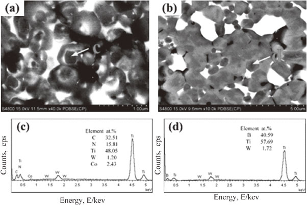
The microstructure of Ti(C, N)–TiB2–WC–Co cermets, with different amounts of WC, is shown in Fig. 6. It can be seen that the micro-morphology of the Ti(C, N)–TiB2–WC–Co cermet consists of WC phase (bright-white), Co binder (off-white), Ti(C, N) matrix phase (gray), TiB2 phase (dark-gray), and holes (black-colored). When the WC content increases from 0 to 10 mass%, the distribution of Co binder becomes uniform at the hard phase grain boundaries. However, the agglomeration occurs with further increase in WC content to 15 and 20 mass%, which can be attributed to the increased wettability between (W, Ti)(C, N) solid-solution and binder. The agglomeration of the binder is due to the formation of CoW2B2 and Co3C compounds in the cermet, which may reduce the wettability and fluidity of the binder. In addition, as the WC content increases from 15 mass% to 20 mass%, the microstructure shows a gradual increase in the core-ring structure (red-colored circle) grains. It has been reported that an appropriate amount of carbide phase, such as Mo2C, WC and TaC, in Ti(C, N)-based cermet leads to different metal contents in different regions due to different dissolution-precipitation rates of metals, resulting in a typical core-ring structure in the SEM-BSE mode.21,28,29) Moreover, Fig. 6 reveals that there are two types of core-ring structures. As shown in Fig. 7, the 1st type of core-ring structure consists of a black-colored core phase, white-colored inner ring phase and black-colored outer ring phase (Fig. 6(a)). The thickness of black-colored core phase ranges from 200 to 300 nm, the thickness of white-colored inner ring phase ranges from 20 to 50 nm, and the thickness of the black-colored outer ring phase ranges from 100 to 200 nm. The EDS analysis of the core-ring structure is presented in Fig. 7(c), showing the presence of Ti, C, N, W and Co. Hence, the core-ring structure can be related to the dissolution and precipitation of WC. The 2nd type of core-ring structure consists of black-colored core phase and gray-colored outer ring phase (Fig. 7(b)) with the thickness range of 300–500 nm and 200–400 nm, respectively. The EDS analysis of the 2nd type of core-ring structure shows the presence of Ti, B and W, corresponding to TiB2 (Fig. 7(d)).

It has been reported that the dissolution-precipitation mechanism forms the black-colored core, and white-colored inner ring and gray-colored outer ring structure.28,30,31) First, the WC starts to dissolve at the eutectic temperature and the dissolution completes at 1300°C. In the presence of excessive WC, a part of WC dissolves at the eutectic temperature and the remaining WC dissolves during the liquid phase sintering. The inner ring phase is precipitated after the dissolution of WC into the liquid phase, i.e., Co, and the formation of (Ti, W)(C, N) on Ti(C, N) surface by nucleation. The outer ring phase is formed during the liquid phase sintering when the sintering temperature exceeds the eutectic point. Moreover, the dissolution of WC into the binder phase increases with further increase in sintering temperature. When the saturation limit is reached at a certain temperature, a composite (Ti, W)(C, N) solid-solution precipitates out of the binder phase in the inner ring phase or Ti(C, N) surface. The core, inner ring and outer ring phases exhibit the same lattice structure and similar lattice constants, indicating excellent coherency in terms of interface. Even though both the inner and outer ring phases are formed by the dissolution and precipitation of carbide, the amount of metallic elements, i.e., Ti and W, is different in both rings, where the inner ring is W-rich and the outer ring phase is Ti-rich. Owing to the difference in W and Ti content, the BSE-SEM image shows a core-ring structure with clear contrast.
The 2nd type of core-ring structure is related to TiB2. Liu et al.32) have discovered the formation of a core-ring structure, consisting of TiB2 core and B4MoTi ring, during the preparation of Ti(C5N5)–TiB2–(W7Ti3) C composite ceramic tools. They have suggested that the formation of the core-ring structure can be ascribed to the accelerated diffusion of B into the Ni–Mo system. Then, B and Mo atoms formed B4MoTi solid-solution during the sintering process. Also, Mo atoms diffused into both Ti(C, N) and TiB2, and formed the core-ring structure of Ti(C, N) and TiB2. Therefore, it is speculated that the 2nd type of core-ring structure, related to TiB2 in the SEM-BSE image, can be related to the diffusion of W atoms. However, the formation mechanism requires further investigations.
The fracture morphology of Ti(C, N)–TiB2–WC–Co cermets, with different amounts of WC, is shown in Fig. 8. One should note that the Ti(C, N)–TiB2–WC–Co cermets exhibited a combination of transgranular (yellow-colored circle) and intergranular (orange-colored circle) fracture at a given concentration of WC. The transgranular fracture is characterized by the propagation of crack through the grains. A large amount of fracture energy is required due to the high hardness and strength of the ceramic phase. On the other hand, the intergranular fracture occurs due to the propagation of cracks through the grain boundary. The tortuosity of the grain boundary greatly increases the crack propagation average free path, which consumes more fracture energy. However, a single fracture mode results in lower performance and, therefore, the combination of transgranular and intergranular fracture endows excellent performance to the composite.33–35) At WC content of 0 mass%, the cermet mainly exhibits a transgranular fracture as well as some holes in the crystal, rendering inferior mechanical properties. However, the transgranular fracture mode initially increases with the increase of WC content from 5 to 20 mass%, followed by a gradual decrease. At WC content of 20 mass%, a high concentration of pores (red-colored circles) facilitates crack propagation and generates intergranular fracture. Additionally, the average grain size of Ti(C, N)–TiB2–WC–Co cermets with WC content from 5 to 20 mass% are 0.691 µm, 0.364 µm, 0.414 µm, 0.453 µm, 0.469 µm, and 0.484 µm, respectively. The grain size are measured by Image J software in Fig. 8(a)–(e) (Average value of about 200 data).36) It can be drawn that the addition of WC significantly reduces grain size of cermets, and the, which can improves the mechanical properties of cermets.

The microhardness, fracture toughness and bending strength of Ti(C, N)–TiB2–WC–Co cermets, with different amounts of WC, after sintering at 1400°C are shown in Fig. 9. It can be seen that the microhardness, fracture toughness and bending strength initially increase with the increase of WC content, followed by a gradual decrease. On the one hand, more W and C elements are dissolved in the binder phase with the increase of WC content, strengthening the binder phase due to solution hardening.37) On the other hand, despite the increase in grain size according to the Hall–Petch formula, the porosity initially decreases with the increase of WC content from 5 to 20 mass%, followed by an increase. Hence, the low strength and hardness can be ascribed to the large grain size of the former and high porosity of the latter. The high porosity facilitates the propagation of cracks, requiring less fracture energy and leading to the low toughness. The highest hardness, bending strength and fracture toughness were found to be 2010 HV10, 725 MPa and 7.21 MPa·m1/2, respectively.


