Mechanics of Materials
Effect of Bonding Temperature on Microstructure and Mechanical Properties of Zircaloy-4/Ti/Ag/304L Diffusion Bonded Joints
2020 Volume 61 Issue 12 Pages 2307-2311

Details
2020 Volume 61 Issue 12 Pages 2307-2311
Vacuum diffusion bonding of Zircaloy-4 (Zr-4) and 304L stainless steel by using pure Ti and pure Ag as multiple interlayers was carried out at the bonding temperatures of 800–900°C for the bonding time of 30 min under the bonding pressure of 12 MPa. The effect of the bonding temperature on the interfacial microstructure and mechanical properties of the joints was studied. The results showed that the interface zone of the joints was transited from 304L/Ag/α-Ag+TiAg/Ti/Ti(Zr)/Zr(Ti)/Zr-4 to 304L/Ag/α-Ag+TiAg/Ag(Ti, Zr)2/Ti(Zr, Ag)/Ti(Zr)/Zr(Ti)/Zr-4 with the bonding temperature increased to 900°C while the TiAg content of α-Ag+TiAg layer decreased. Shear strength of the joints increased with the increasing of the bonding temperatures, and the maximum shear strength of 111.2 MPa was reached at 900°C. The fracture occurred in the Ag layer, which was mainly due to the low mechanical properties of Ag.

Fig. 1 The schematic diagram of the assemblies of 304L SS and Zr-4 using Ag and Ti as the multiple interlayers.
Zirconium (Zr) alloys are used as the materials of the fuel cladding tube and the pressure tube in nuclear reactors, because of their low thermal neutron absorption cross-section, good processability, excellent mechanical properties at elevated temperature, good corrosion resistance to steam and high temperature water.1) Stainless steel (SS) are traditional alloy materials, which have the characteristics of corrosion resistance, thermostability, creep resistance and low price. SS with the high cost performance are widely used as out-of-core structural materials in nuclear reactors.2) Therefore, it is necessary to join Zr alloys with SS in nuclear reactors. However, joining Zr alloys with SS by fusion welding is difficult due to the large difference of the chemical compositions between them, which result in the segregation of chemical species and the formation of brittle intermetallic compounds (IMCs) in the welding joints, and thus weaken the mechanical properties and the corrosion resistance of the welding joints.3) At high temperature, Zr is also easy to react with the elements of O, N and H to increase the brittles of the welding joints.4) Furthermore, the thermal expansion co-efficient of the two materials is so different that the welding joints may produce the large internal stress, and thus be prone to crack.5)
Vacuum diffusion bonding is especially suitable for joining the dissimilar materials with the different physical and chemical properties.6,7) Owing to the bonding process being carried out in vacuum, the reaction between Zr and the elements of O, N and H can be effectively avoided. Joining Zr alloys with SS can be achieved by the direct diffusion bonding. However, the brittle IMCs produced seriously affect the properties of the joint.8,9) Some metals, such as Ni,10) Ti,11) Ta,12) have been used as a single interlayer materials of the diffusion bonding between Zr alloys and SS. Although the direct contact between Zr alloys and SS is effectively avoided and the formation of brittle Zr–Fe, Zr–Cr, Zr–Ni IMCs is prevented, other unexpected IMCs can be formed like Ni5Zr, NiZr, TiFe2, Ti2Fe, TiCr2, TaFe2 and TaCr2. Diffusion bonding with multiple interlayers has been proved to be a very novel and practical method.13–15) Ag is often used as the main element of brazing filler materials and diffusion interlayer in the brazing and diffusion bonding between SS and other materials.16,17) Furthermore, the IMCs of TiAg and Ti2Ag formed between Ag and Ti have little brittleness and some toughness.18,19) Some researchers used Ag as the diffusion interlayer to achieve the joining of Ti alloy and SS.18–21) According to the Ti–Zr binary phase diagram, it can be known that the two elements have good compatibility, can form the infinite solid solution without the production of the brittle IMCs.22) Therefore, in this study, Ti and Ag were selected as the multiple interlayers to diffusion bond Zircaloy-4 (Zr-4) and 304L SS. The interfacial microstructure and distribution characteristics of the joints were analyzed, and the influence of the bonding temperatures on the interfacial microstructure and the mechanical properties of the joints was studied.
Commercially available Zr-4 and 304L SS with the plate thickness of 4 mm were used as the substrate materials in this work. The chemical composition of the substrate materials is shown in Table 1. The samples were machined into the 10 mm × 10 mm × 4 mm bulk by wire-electrode cutting. The interlayer materials were 99.99% of Ti foil and Ag foil with the thickness of 50 µm.

The surfaces of the samples to be bonded were grounded up to 1500 grit by silicon carbide abrasive paper, subsequently, were polished using 3 µm diamond. Finally, all of the specimens were ultrasonically cleaned in acetone for 15 min and dried in cool air. The samples were assembled in the following order: 304L SS, Ag, Ti, Zr-4, as showed in Fig. 1, and were then put into the vacuum chamber. The process parameters used in this study were the bonding temperature of 800–900°C, the bonding time of 30 min and the bonding pressure of 12 MPa. All of the bonding processes were carried out in a vacuum of ≤3 × 10⁻³ Pa. The specimens were initially heated up to 700°C at a heating rate of 20°C/min and held for 10 min, then heated up to the bonding temperature at a heating rate of 10°C/min. After bonding, the assemblies were slowly cooled in vacuum furnace to room temperature.

The schematic diagram of the assemblies of 304L SS and Zr-4 using Ag and Ti as the multiple interlayers.
Samples were prepared by the conventional metallographic procedure, and then were etched in the chemical etchant (20 ml of hydrofluoric acid + 90 ml of nitric acid + 90 ml of distilled water). The microstructure and the chemical composition of the joints were examined by FEI Quanta 250 field emission scanning electron microscopy (FE-SEM) equipped with X-maxn energy-dispersive spectroscopy (EDS). A universal testing machine (MTS-CMT5105) was used to perform the shear test with a cross-head speed of 0.5 mm/min, using the arrangement shown in Fig. 2. The microhardness of the joint was measured with a load of 25 gf and a loading time of 15 s using the HXD-1000TM microhardness tester. The phase constitution on the fractured surface of the joints was identified by the means of Panlytical empyrean X-ray diffraction system (XRD).

Mechanical arrangement for shear test of the joints.
Figure 3 shows the microstructures and EDS line scanning of the joints at the different bonding temperatures. At the bonding temperatures of 800°C and 850°C (Fig. 3(a) and 3(b)), the diffusion reaction zone of the joints can be divided into five layers: I, II, III, IV and V. At the bonding temperature of 900°C (Fig. 3(c)), the diffusion reaction zone of the joint can be divided into four layers: I, II, III and IV. Table 2 shows the results of EDS point analysis and the possible phases at each marked point in Fig. 3.

Microstructures and EDS line scanning of the 304L/Ag/Ti/Zr-4 joints at the different bonding temperatures: (a), (d) 800°C, (b), (e) 850°C and (c), (f) 900°C.
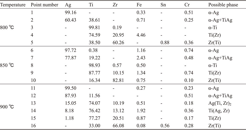
According to the results of EDS line scanning and EDS point analysis, the interfacial structure of the joints shown in Fig. 3(a) and 3(b) was 304L/Ag/α-Ag+TiAg/Ti/Ti(Zr)/Zr(Ti)/Zr-4.15) The EDS line scanning and EDS point analysis of I, II and IV layers in Fig. 3(c) were basically the same as those of I, II and V layers in Fig. 3(a) and 3(b), respectively. They can be identified as Ag layer, α-Ag+TiAg layer and Zr(Ti) layer, respectively. The III layer of Fig. 3(c) was Ag–Ti–Zr mixed layer, which can be divided into three sub-regions: α, β, γ. Sub-region α had a relative constant composition of Ag (15.05 at%), Ti (74.07 at%), Zr (10.19 at%) (point 13 in Fig. 3(f)), which was identified as Ag(Ti, Zr)2.23) Sub-region β had a continuous concentration gradient distribution of Ti, Zr and Ag. Because Ti and Ag has a certain solid solubility, it can be considered that Ti(Zr, Ag) solid solution was formed in the sub-region β. In sub-region γ, the content of Ag was very low and the content of Ti and Zr gradually varied. Moreover, the content of Ti was higher than that of Zr. So sub-region γ is considered to be Ti(Zr) solid solution region. Therefore, the interfacial structure of the joint showed in Fig. 3(c) was 304L/Ag/α-Ag+TiAg/Ag(Ti, Zr)2/Ti(Zr, Ag)/Ti(Zr)/Zr(Ti)/Zr-4.
Figure 4 shows the ratio of α-Ag and TiAg, and the layer thickness in α-Ag+TiAg layer at the different bonding temperature. It can be known from Fig. 4 that the layer thickness and the content of α-Ag increased with the increase of the bonding temperature, whereas the content of TiAg decreased. During the diffusion bonding, the IMCs in the joints did not form immediately, but had an incubation period. The higher the bonding temperature was, the shorter the incubation period of IMCs was. The formation of IMCs could reduce the interdiffusion ability of atoms on the diffusion interface.24,25) With the increase of the bonding temperature, on the one hand, the initial interdiffusion ability on Ag/Ti interface was enhanced, and there were more Ag atom and Ti atom mutually diffusing across the Ag/Ti interface. On the other hand, TiAg IMCs were formed earlier and thus the number of interdiffusion atoms was reduced. Under the combined action above, the total amount of interdiffusion atoms on the Ag/Ti interface was restricted, which limited the amount of TiAg IMCs. The atoms that crossed the Ag/Ti interface can continue to diffuse at a faster rate because there was no TiAg IMCs on the way of their diffusion. Therefore, the thickness of α-Ag+TiAg layer increased with the increase of the bonding temperature. Due to a limited total amount of TiAg IMCs in α-Ag+TiAg layer and an increased thickness of α-Ag+TiAg layer, the content of TiAg IMCs in the α-Ag+TiAg layer was decreased.

Percentage of α-Ag and TiAg, and layer thickness in α-Ag+TiAg layer at the different bonding temperatures.
The microhardness curves of the joints at the different bonding temperatures are shown in Fig. 5. It can be seen from Fig. 5 that the variation tendency of microhardness curves had no significant difference among the curves. The microhardness of the 304L SS substrate and the Zr-4 substrate were about 270 HV and 195 HV, respectively. And the microhardness value of the 304L SS substrate was highest in the joint. Adjacent to the substrate of 304L SS, the microhardness value of the Ag interlayer was about 75 HV which was lowest in the joint and only was 27.7% of the one of 304L SS. Close to the Ag interlayer, α-Ag+TiAg layer had about 84 HV of microhardness which was slightly higher than that of the Ag interlayer. For the joints bonded at 800°C and 850°C, the microhardness of the Ti interlayer was about 210 HV, which was higher than that of the Zr-4 substrate. The microhardnesses of Zr(Ti) and Ti(Zr) solid solution were higher than that of the Ti interlayer and the Zr-4 substrate due to solid solution strengthening. For the joints bonded at 900°C, the Ti interlayer was completely depleted. The microhardnesses of Ag(Ti, Zr)2 and Ti(Ag, Zr) formed by diffusing Ag atoms into the Ti(Zr) solid solution were lower than that of Ti(Zr) solid solution.

Microhardness variation across the 304L/Ag/Ti/Zr-4 interface for joints bonded at the different bonding temperatures.
Figure 6 shows the relation of the shear strength of the joints and the bonding temperatures. As it can be seen that the shear strength at 800°C, 850°C and 900°C were 20.1 MPa, 58.6 MPa and 111.2 MPa, respectively. The shear strength of the joints increased significantly with the increase of the bonding temperature. Figure 7 shows the macro fracture morphology of the 304L SS substrate side of the joints at different temperatures. The areas surrounded by red lines were considered as diffusion zone (DZ), which can be divided into two zones, i.e., insufficiency diffusion zone (IDZ) and effective connected zone (ECZ). IDZ was between red line and yellow line while ECZ was surrounded by yellow lines. As shown in Fig. 7, the IDZ formed at 800°C was biggest, the ECZ was smallest. With the increase of the bonding temperature the IDZ decreased and the ECZ increased. Generally, with the increase of bonding temperature or bonding time, more brittle IMCs would be formed in the reaction layer, weakening the strength of bonded joints.26,27) In this study, Ag/Ti multi-interlayer were used. IMCs was not produced by Ag on the SS side with the main elements of SS, while the infinite solid solution was formed by Ti and Zr without the production of the brittle IMCs.22) Only TiAg IMCs was formed in the reaction zone of Ag and Ti, and it was reported that the TiAg IMCs was not as brittle as many other Ti-based IMCs, and had considerable toughness.28,29) In addition, as described earlier (part 3.1), the higher the boding temperature was, the less TiAg IMC formed in α-Tg+TiAg layer was. Therefore, the shear strength did not decrease at a higher temperature of 900°C. On the other hand, with the increase of bonding temperature, the atoms on bonding interfaces diffused more fully, forming larger ECZ, which also made the shear strength value higher.

Shear strength of 304L/Ag/Ti/Zr-4 joints at the different bonding temperatures.

Macro surface of the shear fracture of the 304L/Ag/Ti/Zr-4 joints bonded at: (a) 800°C, (b) 850°C and (c) 900°C.
XRD analysis of the shear fracture surface of the joints are shown in Fig. 8. Figure 8(a) and 8(b) correspond to the shear fracture surface of the Zr-4 side and the 304L SS side, respectively. Ag and Fe(Ni) were detected on the shear fracture surface of the 304L SS side, and Ag was detected on the shear fractured surface of the Zr-4 side when the bonding temperature was 800°C, which indicated that the shear fracture of the joint mainly occurred on the interface between the 304L SS substrate and the Ag interlayer. While only Ag was detected on the shear fracture surface of both the 304L SS side and the Zr-4 side when the bonding temperature was 850°C and 900°C, indicating that the shear fracture of the joints mainly occurred in the Ag interlayer. From the perspective of diffusion dynamics, the increase of temperature is helpful to improve the diffusion degree, which should be the main reason for the improvement of mechanical properties of joints. The atoms were fully diffused within the ECZ, forming an effective region which could support the load, whereas the IDZ with insufficient diffusion could not bear the shear load. The fracture of the joint bonded at 800°C was found at the interface of SS-304 and Ag interlayer due to the smaller area of ECZ. With the increase of diffusion temperature, the area of ECZ region increased gradually, and the diffusion between SS-304 and Ag was more sufficient. The fracture occurred in the Ag interlayer with the weak mechanical properties. Therefore, for the joints of Zr-4 and 304L SS with Ti and Ag as the multiple interlayers, the weak mechanical properties of Ag was the key factor affecting the joint performance.

XRD patterns of shear fracture interface of the 304L/Ag/Ti/Zr-4 joints: (a) 304L SS side and (b) Zr-4 side.
The research was partly finance supported by the Doctoral Innovation Fund Program of Southwest Jiaotong University [grant number D-CX201830], the China Scholarship Council [grant number 201707000086, 201907000039] and the national key research and development plan of China (grant number 2017YFB0305905).