1. Introduction
In the die casting process, there still remain many problems of casting defects including blow holes, shrinkage porosity, cold shuts, blisters, soldering reactions, and laminations.1–7)
Blow holes, shrinkage porosity, and cold shuts are well-known casting defects and analytical simulations are widely used for predicting these defects.8–13) Soldering reactions caused by the fusion of the die surface have become a severe problem in the manufacturing process owing to the decrease in production efficiency. The mechanism of soldering reactions has been clarified from physical and chemical perspectives.2,4,14) On the other hand, laminations are often formed on the mold surface by the rapid solidification of the molten metal in zinc alloy die casting. Laminations are a severe problem because they cause stripping on the casting surface and blisters after plating. These defects lead to poor casting quality. Laminations also cause the deposition of zinc on the mold surface.14–17) Since zinc deposits on the mold surface reduce the surface quality of castings, as in the case of soldering reactions, they must be removed. The process of removing zinc deposits from the mold surface significantly reduces productivity. Thus, laminations not only adversely affect the appearance, but also reduce the productivity of castings.
Figure 1 shows defects such as a zinc deposit on a mold surface, a blister after plating, and stripping, caused by laminations formed in the zinc alloy die casting process.

Figure 1(a) shows an image of a zinc deposit on a mold surface after 10,000 shots of die casting. As shown in Fig. 1(a), when molten zinc adheres to the mold surface owing to laminations, the casting surface becomes rough and the surface properties deteriorate, similarly to a surface after a soldering reaction. Laminations have a significant impact on the quality and productivity of castings. The blister shown in Fig. 1(b) not only adversely affects the appearance but also reduces the functionality of castings. The blisters due to laminations after plating are caused by the mechanism explained in a previous paper.17) Figure 1(c) shows a stripping defect formed by a separation caused by laminations that occurred near the mold surface. Stripping defects are also formed by molten metal flows that cannot be fused with each other near the mold surface, that is, by laminations. Therefore, it is very important to prevent the formation of laminations to improve product quality and production efficiency. An evaluation criterion for predicting the risk of laminations was formulated on the basis of the shear rate of a molten metal flow.17) The distribution of the evaluation criterion value allows us to predict where laminations will occur.
Since the flow pattern of the molten metal near the mold surface is affected by viscosity, it is necessary to consider the temperature dependence of the viscosity of the molten metal to more accurately predict the occurrence of laminations.
Therefore, it is very important to predict the temperature distribution on the mold surface in die casting simulations.
The problem is to obtain the mold surface temperature, which fluctuates periodically in the die casting process. The effect of the temperature distribution on the mold surface was not considered in the previous paper.17)
The purpose of this study is to improve the prediction accuracy of the evaluation criterion for laminations. We propose a new method of repeatedly simulating the temperature inside the mold until the mold surface temperature fluctuates stably, using a simple model of the die casting process.
Hereinafter, this simulation method is referred to as cyclic heat transfer analysis. We adopted a coupling analysis method consisting of the cyclic heat transfer analysis of the mold and mold filling analysis that considers the solidification of the molten metal using the spatial distribution of the mold temperature estimated by cyclic heat transfer analysis.
To confirm the validity of the proposed analysis method, we applied the coupling analysis method to a practical zinc alloy die casting. It is important to consider not only the back pressure of the gas inside the mold but also the gas flow to perform an accurate mold filling simulation, and the Navier-Stokes equation for gas-liquid two-fluid analysis was used in the mold filling analysis. Furthermore, the evaluation criterion in the coupling analysis method was applied to the optimization of a gating system to eliminate the occurrence of blisters after plating.
2. Simulation and Prediction Methods
2.1 Cyclic heat transfer analysis of mold
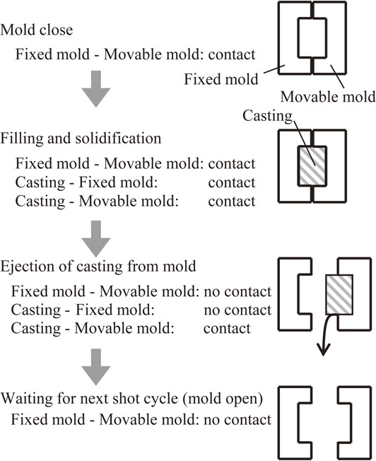
In die casting, a series of processes including mold clamping, injection, mold release, and air cooling are repeated. Figure 2 shows a schematic diagram of die casting. The processes are represented as mold close, mold filling and solidification, ejection, and mold open as shown in Fig. 2. The temperature on the mold surface markedly changes through the four states of clamping, injection, mold release, and cooling. These four states make up one cycle. Throughout the series of processes, the mold surface temperature repeatedly rises and falls in a very short time, and the time average of the mold surface temperature during one cycle gradually rises and converges to a constant temperature.
To simulate the above processes in die casting, we propose a cyclic transfer analysis. By repeating the heat transfer analysis of the mold until the time average of the mold surface temperature in one cycle converges to a constant value, we can obtain the distribution of the mold surface temperature when the mold temperature constantly changes.
In the cyclic heat transfer analysis, the release of latent heat during the solidification of the molten metal is dealt with by the equivalent specific heat method.18) In the next phase, the molten metal flow is analyzed using the temperature distribution on the mold surface predicted by the cyclic heat transfer analysis as the initial condition. In this section, we explain the cyclic heat transfer analysis to obtain the temperature distribution on the mold surface. The thermal energy conservation law between molds and castings can be expressed as follows, ignoring the heat convection and heat generation.
| \begin{equation}
\rho \frac{\partial h}{\partial t} = \nabla \cdot (\lambda \nabla T)
\end{equation}
| (1) |
Here,
T is the temperature, λ the thermal conductivity,
h the specific enthalpy, and ρ the density, which is constant.
Considering the release of latent heat during the solidification of castings, h is expressed as
| \begin{equation}
h = \int_{0}^{T}C_{p}dT + (1 - f_{s})L,
\end{equation}
| (2) |
where
Cp is the specific heat,
fs the solid fraction, and
L the latent heat of solidification.
Equation (3) is obtained by differentiating eq. (2) with respect to T.
| \begin{equation}
C_{\textit{pE}} \equiv \frac{\partial h}{\partial T} = C_{p} - L\frac{\partial f_{s}}{\partial T}
\end{equation}
| (3) |
Substituting
eq. (3) into
eq. (1), the following equation is obtained:
| \begin{equation}
\rho C_{\textit{pE}}\frac{\partial T}{\partial t} = \nabla \cdot (\lambda \nabla T).
\end{equation}
| (4) |
By determining the relationship between the solid fraction and the temperature using this method, we can treat the release of latent heat as a mere unsteady heat transfer equation using the equivalent specific heat
CpE defined in
eq. (3) instead of the specific heat
Cp. By integrating
eq. (4) within an arbitrary control volume and using the Gaussian divergence theorem for the diffusion term on the right side, we can obtain the following governing equation:
| \begin{equation}
\int_{\Omega}\rho C_{\textit{pE}}\frac{\partial T}{\partial t}d\Omega = \int_{S}\lambda \nabla T \cdot \mathbf{n}dS
\end{equation}
| (5) |
In this study,
eq. (5) is discretized by the finite volume method with tetrahedral elements as the control volume.
In the cyclic heat transfer analysis, the temperature of the molten metal, and the contact conditions between the gas, castings, and molds are treated as follows. The temperatures of the molten metal and castings are assumed to be 703 K throughout the filling, solidification, and ejection processes. Contact conditions between the fixed and movable molds are imposed in the closing of the molds. During mold filling and solidification, in addition to the contact conditions between the molds, the contact conditions between the castings and the fixed and movable molds are imposed. When removing castings from the molds, only the contact conditions between the castings and the movable mold are imposed. Finally, the contact conditions between the molds and the air are imposed when waiting for the next shot. The gas temperature is assumed to be 313 K in the closing and opening processes of the molds.
These processes are virtually simulated in the cyclic heat transfer analysis using eq. (5) under the above assumptions.
2.2 Numerical scheme for the two-fluid flow analysis
The fluid motion of the molten metal and the gas was treated using a two-fluid flow analysis model.19–26) In this study, we assumed that the two fluids are incompressible, viscous, and immiscible. As the governing equations, the incompressible Navier-Stokes equations (6) and (8), and the continuity equations (7) and (9) were adopted for each fluid.
Subscripts (l) and (g) represent the molten metal and gas, respectively.
| \begin{align}
\rho^{(l)}\left(\frac{\partial u_{i}^{(l)}}{\partial t} + \sum_{j = 1}^{3}u_{j}^{(l)} \frac{\partial u_{i}^{(l)}}{\partial x_{j}}\right) &- \sum_{j = 1}^{3}\frac{\partial}{\partial x_{j}} \sigma_{i,j}^{(l)} = -\rho^{(l)}g \cdot \delta_{i,3}^{(l)} \\
&\quad (1 \leq i,j \leq 3)\ \textit{in}\ \Omega^{(l)}
\end{align}
| (6) |
| \begin{equation}
div\boldsymbol{u}^{(l)} \quad \textit{in}\ \Omega^{(l)}
\end{equation}
| (7) |
| \begin{align}
\rho^{(g)}\left(\frac{\partial u_{i}^{(g)}}{\partial t} + \sum_{j = 1}^{3}u_{j}^{(g)} \frac{\partial u_{i}^{(g)}}{\partial x_{j}}\right) &- \sum_{j = 1}^{3}\frac{\partial}{\partial x_{j}} \sigma_{i,j}^{(g)} = -\rho^{(g)}g \cdot \delta_{i,3}^{(g)}\\
&\quad (1 \leq i,j \leq 3)\ \textit{in}\ \Omega^{(g)}
\end{align}
| (8) |
| \begin{equation}
div\boldsymbol{u}^{(g)}\quad \textit{in}\ \Omega^{(g)}
\end{equation}
| (9) |
Here,
$\sigma _{i,j}^{(\alpha )} = - p^{(\alpha )}\delta _{i,j} + 2\mu _{\alpha }D_{i,j}$ and
$D_{i,j} = \frac{1}{2}(\frac{\partial u_{i}^{(\alpha )}}{\partial x_{j}} + \frac{\partial u_{j}^{(\alpha )}}{\partial x_{i}})$, 1 ≤
i,
j ≤ 3, α = (
l), (
g), where
$u_{i}^{(\alpha )}$,
p(α), μ
α, ρ
α, and
$\sigma _{i,j}^{(\alpha )}$ are the velocity, pressure, viscosity, density, and stress tensor, respectively.
As the boundary condition for the velocity, we adopted the no-slip condition on the mold surface. Furthermore, we added the following condition for the stress.
In general, surface tension satisfies the jump condition for the normal stress along the interface between the molten metal and the gas as follows:
| \begin{equation}
\sigma_{i,j}^{(l)}\cdot n_{j} - \sigma_{i,j}^{(g)} \cdot n_{j}' = \tau \cdot \kappa \cdot n_{i},
\end{equation}
| (10) |
where τ and κ are the surface tension and its curvature, and
ni and
$n'_{i}$ are the outward unit normal vectors along the interface from the liquid region Ω
(l) side and from the gas region Ω
(g) side, respectively.
Since $n'_{j} = - n_{j}$, using the stress condition (10), the following equations are obtained from eqs. (6)–(9):
| \begin{align}
\rho \cdot \left(\frac{\partial u_{i}}{\partial t} + \sum_{j=1}^{3}u_{j}\frac{\partial u_{i}}{\partial x_{j}}\right) &- \sum_{j = 1}^{3}\frac{\partial}{\partial x_{j}} \sigma_{i,j} = -\rho g \cdot \delta_{i,3}\\
&\quad (1 \leq i, j \leq 3),
\end{align}
| (11) |
| \begin{equation}
div\boldsymbol{u}.
\end{equation}
| (12) |
Here, δ
i,3 represents the direction of gravity. The above formulation is based on the characteristic theory of two-fluid flow analysis.
19–23)
The temperature of the molten metal is obtained from the following energy equation:
| \begin{equation}
\rho C_{\textit{pE}}\frac{\partial T}{\partial t} + (\boldsymbol{u} \cdot \nabla)T = \nabla \cdot (\lambda \nabla T),
\end{equation}
| (13) |
| \begin{equation*}
C_{\textit{pE}} \equiv \frac{\partial h}{\partial T} = C_{p} - L\frac{\partial f_{s}}{\partial T}.
\end{equation*}
|
Here,
T is the temperature, λ the thermal conductivity,
h the specific enthalpy, ρ the density,
Cp the specific heat of the molten metal,
fs the solid fraction, and
L the latent heat of solidification for the molten metal. In the energy
equation (13), the temperature dependence of the viscosity of the molten metal is incorporated to accurately calculate the shear rate near the mold surface. In two-fluid flow analysis that distinguishes between a liquid phase and a gas phase, it is important to accurately capture the shape of the interface between the two phases. The Cahn-Hilliard equation was adopted to accurately capture the motion of the interface between the molten metal and the gas.
27–30) The evaluation criterion for predicting the risk of lamination formation is formulated as follows.
17)
The strain rate Dαβ of a fluid is defined as
| \begin{equation}
D_{\alpha \beta} = \frac{1}{2}\left(\frac{\partial u_{\alpha}}{\partial x_{\beta}} + \frac{\partial u_{\beta}}{\partial x_{\alpha}} \right),\quad (\alpha,\beta = 1,2,3).
\end{equation}
| (14) |
Here,
uα (α = 1, 2, 3) is the velocity and subscripts α and β are indicators in the Cartesian coordinate system. The strain rate
$D_{\alpha \beta }^{e}$ of each tetrahedral element Ω
e is approximated by the finite element method as
| \begin{equation}
D_{\alpha \beta}^{e} = \frac{1}{2V^{e}} (C_{\beta i}u_{\alpha i} + C_{\alpha i}u_{\beta i}),\quad (i = 1,2,3,4),
\end{equation}
| (15) |
where
Ve is the volume of each element Ω
e and
i represents the node number in each element. The shape function ψ
i, and its spatial derivatives
Cαi are defined by
| \begin{equation}
C_{\alpha i} = \int_{\Omega^{e}}\frac{\partial \psi_{i}}{\partial x_{\alpha}}d\Omega^{e}.
\end{equation}
| (16) |
The shear rates in the
x-,
y-, and
z-directions are 2
Dyz, 2
Dzx, and 2
Dxy, respectively.
The sum of the shear rates in all directions is
| \begin{equation}
S^{e} = 2(D_{xy}^{e} + D_{yz}^{e} + D_{zx}^{e}).
\end{equation}
| (17) |
Here,
Se depends on the flow field, which changes with time.
By integrating the shear rate Se over the time for which molten metal exists in an element Ωe before it is completely solidified, the evaluation criterion is defined as
| \begin{equation}
f^{e} = \frac{\displaystyle\sum_{n=1}^{N^{e}}dt_{n}S_{n}^{e}}{\displaystyle\sum_{n=1}^{N^{e}}dt_{n}},
\end{equation}
| (18) |
where
Ne is the total number of calculation steps during which molten metal exists in the element. It is suggested that the smaller the value of
fe, the higher the risk of lamination formation.
If the positions of laminations can be accurately predicted using the evaluation criterion, it will be possible to optimize the gating system before manufacturing to suppress lamination formation.
2.3 Application of prediction method to practical die casting
To confirm the validity of the proposed criterion fe, a mold filling simulation and an actual die casting were carried out. The formation of laminations predicted using the evaluation criterion by mold filling simulation was compared with the blisters caused by laminations observed in the actual die casting. Figure 3(a) shows the shape of the mold used for the simulation and die casting experiment. Figures 3(b), (c) respectively show the shape of the castings and the gating system for the zinc alloy die casting used in the validation. Several overflows are attached to each cavity. A vent for gas leakage is attached to each overflow.
In the die casting process, molten metal is injected from the sprue and filled into the product through the gate. The gate position is very important, because it is the inlet that fills the product with the molten metal, and the gate position affects the flow pattern inside the mold of the product.
The gating system in Fig. 3(c) is hereinafter referred to as a conventional gate. ZDC1 zinc alloy is used as the molten metal and maraging steel is used as the mold material. Molten zinc was injected from a melting pot at a temperature of 703 K using a plunger at a maximum speed of about 0.6 m/s, which is a relatively low injection speed. When the injection speed is low, the cooling rate is increased and the solidification rate is also increased accordingly.
The rapid solidification causes laminations, which in turn cause blisters after plating. The low injection speed set in this study was used to confirm the prediction accuracy of the analysis by considering the mold surface temperature. The cycle time of the die casting process, which consists of the main stages of clamping, injection, ejection, and cooling, was set to 5.0 s. After the die casting process, the plating process including that of the underlying copper was carried out, and the appearance of the plated products was inspected. Here, we explain the conditions of the numerical simulation. In the cyclic heat transfer analysis of molds, a mesh divided into 3,174,742 tetrahedral elements was used. The state of contact between castings and molds depends on the pressure of the molten metal and the state of solidification shrinkage. A wide range of the heat transfer coefficients between castings and molds of 1,000 to 8,000 W/(m2K) has been reported.
In this study, the heat transfer coefficient between castings and molds was set to 5,000 W/(m2K), assuming there is no air gap between the castings and the molds. The density, specific heat, and thermal conductivity of the mold were set to 8,020 kg/m3, 402 J/(kg·K), and 23.1 W/(m·K), respectively.
The initial temperatures of the molten zinc and molds were set to 703 K and 293 K, respectively, and 50 cycles of shots were calculated to obtain the temperature distribution reached in a periodic steady state. In the mold filling simulation, the temperature distribution on the mold surface obtained by cyclic heat transfer analysis was used as the initial condition of the energy equation (5). The heat transfer coefficient between the castings and the molds was set to 20,000 W/(m2·K) in the injection and cooling processes. The latent heat of solidification of the molten metal was set to 115.6 kJ/kg, which is that of ZDC1. In this study, the temperature dependence of the viscosity was considered, and Fig. 4 shows the temperature dependence of the viscosity used in the mold filling simulation. As the inlet condition, a constant velocity of 7.5 m/s, converted from the plunger speed of 0.6 m/s, was set on the apical surface of the sprue.
3. Results and Discussion
3.1 Simulation results for conventional gating system
Under the conditions expressed in section 2.3, the cyclic heat transfer analysis was carried out using the mold shape shown in Fig. 3(a). Figure 5 shows the time history of the mold surface temperature at point P indicated in Fig. 3(c).

As shown in Fig. 5, the temperature rises rapidly with repeated vibrations in a short time. The temperature of the mold surface reaches a stable periodic fluctuation after around 40 shots, i.e., 200 s. From Fig. 5, it is confirmed that the maximum temperature exceeds 463 K, the minimum temperature reaches 403 K, and the mold temperature fluctuates and gradually rises until the average temperature reaches 433 K, which is close to the temperature measured near the mold surface when controlling the mold temperature with cooling water of 313 K. Figure 6 shows the temperature distribution of the mold surface immediately before injection, when the temperature on the mold surface reaches a stable periodic fluctuation after 50 shots for the conventional gating system. A cooling pipe with water of 313 K are installed inside the molds. Since the mold surface temperature near the gate is relatively high, it can be seen that the mold surface in this area stored the heat. The temperature distribution of the mold surface is not symmetrical and the temperature in the upper half is relatively high owing to the effect of the cooling pipe. The mold surface temperature affects the viscosity of the molten metal and also the flow pattern. That is, the distribution of the mold surface temperature affects the formation of laminations. As mentioned above, it is considered that the asymmetry of the mold surface temperature affects the formation of laminations after die casting and also affects the positions of blister defects after plating. Figure 7 shows the filling sequence for the conventional gating system. As can be seen from Fig. 7, the molten metal reaches the mold surface opposite the gate at a filling rate of 44%. Subsequently, even when the filling rate reaches 50%, areas A and B are not filled. Figure 8 shows the velocity field of the molten metal at a filling rate of 86%. It can be seen that the velocity of the molten metal in areas A and B is markedly lower than that in other areas. From the flow pattern and velocity field of the molten metal, the flow in areas A and B shown in Fig. 8 is relatively stagnant, and the shear rates in these areas are small.

Figure 9(a) shows the distribution of fe, the criterion for predicting lamination formation, estimated from the shear rate of the molten metal flow in the vicinity of the mold surface. fe is smaller in areas A and B than elsewhere. The results show that the laminations are much more likely to form in areas A and B than in other areas. In particular, fe in area A is extremely small, so it was predicted that the risk of lamination formation in this area is extremely high. From these results, it was predicted that the risk of blister occurrence due to laminations is highest in area A. The actual die casting and plating were performed using the conventional gating system. Then, a visual inspection of 1,000 castings was performed using a microscope to confirm the positions of blisters that occurred on the castings. Figure 9(b) shows the positions of blisters after the actual die casting and plating processes. By comparing the actual die casting results with the evaluation criterion predictions, we can see that there is very good agreement. As shown in Fig. 9(b), it was found that 88.3% of the blisters that formed in actual die casting occurred in area A and 8.6% occurred in area B. Figure 9(c) shows microscopy images of the blisters in areas A and B, which occurred after the actual die casting and plating processes. Figure 10 shows cross-sectional scanning electron microscopy (SEM) images of blisters in areas A and B shown in Fig. 9(c). From Figs. 10(a), (b), it was confirmed that a thin layer of zinc alloy was attached to the plating layer; this thin layer is a chill layer formed by rapid solidification. The crystal grain size in the chill layer is extremely small, and a dendrite structure was observed in the layer inside the casting. From these images, we can see that these blisters are caused by laminations.

In this section, we explain the process of optimizing of the gating system to reduce the incidence of casting defects. First, from the simulation results using the conventional gating system, we pay attention to the flow pattern of the molten metal. It was confirmed that the positions where laminations occur coincide with stagnation areas where the velocity of the molten metal is markedly lower than that of other areas. From this result, a gate with no stagnation areas is considered to be the optimal gating system for eliminating laminations. Therefore, we have designed a gating system that prevents pressure loss due to the molten metal colliding with the mold surface and enables smooth filling.
A simulation using the optimized gating system was performed and it was found that no lamination occurred using the evaluation criterion. Finally, it was confirmed that laminations were eliminated in actual die casting adopting the optimized gating system.
The results for the conventional gating system show that inhibiting the rapid solidification of molten metal is very important to the reduction of lamination formation. In this study, the gating system was optimized so that hot molten metal could flow into the castings in a very short time in order to avoid rapid cooling from the mold surface. Figure 11 shows the gating system after optimization to prevent the local stagnation of the flow of the molten metal in the castings. The new gate is wider and located downstream. This gating system was designed to flow in directions C and D from portion A of the gate, and to flow in direction E from portion B of the gate. Figure 12 shows the temperature distribution of the mold surface immediately before injection after 50 shots for the optimized gating system. It can be confirmed that the distribution of the die surface temperature shown in Fig. 12 is different from that for the conventional gating system shown in Fig. 6. This is due to the difference of mold design. Figure 13 shows the filling sequence for the optimized gating system. As expected, and shown in Fig. 11, the molten metal is pushed upward from the downstream side, and the molten metal flow does not reach the mold surface opposite the gate and does not diverge, as shown in Fig. 7. Figure 14 shows the velocity field when the filling rate reaches 86%. No decrease in the flow rate of molten metal in areas A and B was observed by comparison with the velocity field shown in Fig. 8. Figure 15 shows the distribution of fe predicted by simulation for the optimized gating system. The risk of lamination formation, as shown in Fig. 9(a), cannot be confirmed from Fig. 15. The predicted result shows that no blisters were caused by lamination, when using the optimized gating system. We performed a visual inspection of 1,000 castings fabricated by actual die casting and plating using the conventional and optimized gating systems. When using the conventional gating system, the incidence was around 10%. On the other hand, no blisters were observed when using the optimized gating system, as predicted in Fig. 15.

Figure 16 shows cross-sectional SEM images of castings after actual die casting using the optimized gating system in areas H, I, J, and K, where blisters due to laminations occurred when using the conventional gating system. We can observe the dendritic structure in all SEM images. On the other hand, the chill layers that cause laminations observed in Fig. 10 were not detected in any of the areas. From this result, it can be seen that the solidification rate of molten metal for the optimized gating system is lower than that for the conventional gating system.
The suppression of rapid solidification markedly reduces the formation of laminations and eliminates blister defects caused by laminations. It was confirmed from these results that the optimization of the gating system is very effective in reducing the occurrence of blister defects after plating.


