Abstract
The main purpose of precision blanking in press stamping is to suppress fracture of the cut surface. The principle is attainable by applying hydrostatic stress on the workpiece by various contrivances, so that the workpiece can maintain its ductility for suppression of fracture. Stainless steel, which is commonly used in medical components, is also known to be a ductile material, but one of problematic characteristics of austenitic stainless steel is martensitic transformation. The phenomenon is that the ductile austenite phase is changed to the brittle martensitic one by processing strain. Therefore, in this study, the effect on the cut surface from martensitic transformation near it in the precision blanking process was investigated. As a result, it was proved that there was a difference in the occurrence or non-occurrence of fracture of the cut surface due to the difference in the strain-induced martensitic transformation.
1. Introduction
In recent years, medical treatment tools used in surgery have been miniaturized for the purpose of reducing damages of patients. As the size of parts makes smaller, the manufacturing becomes difficult and the accuracy is also affected.1) Therefore, laser processing, etching processing, electron beam processing, and the like have been used in conventional methods.2–4) However, these methods have problems in productivity and cost. From various processing methods, the authors chose the press blanking which has excellent productivity and cost reduction, and carried out the verification of reality regarding the micro processing method. Blanking is a method that uses a tool composed of a punch and a die, applies a large shear deformation to the material in the clearance area between the tools of cutting edge, and finally it breaks into the material to separate it. In general blanking, a cut surface with low quality, called a fractured surface, is formed in the brittle area. Precision blanking is a method to suppress the fracture surface. The feature is to use the effect of increasing the ductility of the metal material by applying hydrostatic pressure near the punch and die cutting edge.5) In order to increase the hydrostatic pressure in the vicinity of the tool, authors has verified the suppression of fracture by using a narrow clearance (finish blanking) and a negative clearance (extrusion blanking). As a result, it was shown that the negative clearance blanking method, which was presumed that the hydrostatic pressure becomes higher, was advantageous in terms of suppressing the fracture surface.6) Moreover, we have clarified the suppression mechanism of the fracture by an FE analysis and EBSD analysis.7)
On the other hand, focusing on materials used for medical components, austenitic stainless steels are often used as the materials from the viewpoints of both corrosion resistance and biocompatibility. In particular, JIS SUS304 and JIS SUS316L materials are used in many medical components.8) However, it is known that these materials will cause phase transformation from an austenitic phase to a martensitic one when subjected to processing strain. Their properties are, thus, clearly different from those of other metallic materials, and it is considered that several influences could appear when the part is processed or fabricated. Until now, the relationship between martensitic transformation and processing strain has mainly been investigated by tensile tests,9–11) and the effect of press blanking has not been investigated.
In this study, the relationship between the strain-induced martensitic transformation and the shear cut surface was investigated by using the precision press blanking process often used for the purpose of fracture suppression. Specifically, two austenitic stainless steels with different degrees of strain-induced martensitic transformation were used to investigate the effect of martensitic transformation on the cut surface quality in the narrow clearance blanking (finish blanking).
2. Experimental Procedure
2.1 Material
Two types of workpiece were used, i.e., SUS304 one and SUS316L one respectively made by TOKUSHU KINZOKU EXCEL Co., Ltd. The thickness was 0.20 mm and the width was 20 mm. It has known that the strain-induced martensitic transformation is closely related to the dislocation.12) The behavior is considered to vary greatly depending on the crystal orientation, so we confirmed that the grains are equiaxed grains with no uniform crystal orientation.
The chemical compositions of the two materials are shown in Table 1, and the mechanical properties obtained from the tensile test and the hardness test are respectively shown in Table 2. The stress-strain curves obtained from the tensile test is shown in Fig. 1. For the tensile test, JIS13B (JIS Z2201) specimens were used, the tensile speed was 5 mm/min, and the test temperature was room temperature. The hardness test was performed at room temperature using a micro Vickers hardness equipment with a load of 0.98 N and holding time of 10 second. Next, for the two materials, the so-called Md30 index,13) which is a quantitative indication of the stabilities of austenite, was calculated to be 36°C for SUS304 and −58°C for SUS316L using eq. (1). The lower the temperature, the more stable the austenite is, indicating that it is difficult to transform martensite by processing.
| \begin{align}
\text{Md$_{30}$}& = 551 - 462(\text{C}+\text{N}) - 9.2\text{Si} - 8.1\text{Mn} - 13.7\text{Cr}\\
&\quad - 29.0(\text{Ni}+\text{Cu}) - 18.5\text{Mo} - 68.0\text{Nb}
\end{align}
| (1) |

Table 1 Chemical composition of the JIS stainless steel materials (mass%).

Table 2 Mechanical properties of JIS work materials.
In order to obtain a blanked product with high accuracy, the cut surface of the product should not be fractured. Therefore, in this experiment, as shown in Fig. 2 a finish blanking, which is one of precision blanking processes6) and capable of manufacturing a die even by micro-machining, was used. More specifically, the punch diameter and the die diameter was set to 2.000 mm and 2.004 mm respectively, and the clearance between the punch and the die was set to 2 µm (1% ratio over the plate thickness t). The die cutting edge has a minute R portion, and a counter-punch was installed in the beneath plate. The press machine has maximum pressure capacity of 50 kN with servo type screw press, and blanking step was performed at a shear rate of 5 mm/s in room temperature.
3. Results and Discussion
3.1 Cut surface
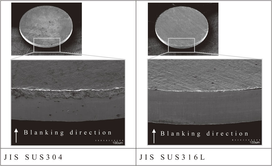
Figure 3 shows an SEM image of the blanked product obtained by the finish type FB method. As is shown before, about 20% fracture surface of the plate thickness was observed on the cut surface in SUS304. On the other hand, the fracture surface in SUS316L could not be observed, and the whole surface was full shear surface. As a general knowledge of shearing, it is known that the higher ductility workpiece has the higher shear surface ratio on the cut face.14) As for the two materials used in the present experiments, the elongation value for the tensile test of SUS304 is higher than that of SUS316L, which differs from the general knowledge of shearing as stated above.
3.2 Discussion on EBSD analysis
It is absolutely essential to find the truth of the above relevant question/phenomenon. Here is our hypothesis: although the ductility of SUS304 is higher than that of SUS316L, this ductility itself is suspected to be one of the causes of fracture on the cut surface. This hypothesis is strengthened because the martensitic phase material is known as a brittle material.15) Accordingly, the shear deformation area was analyzed using EBSD (electron back-scatter diffraction) in which the crystal phase distributions can be analyzed from the analysis of crystal orientation. The sample for EBSD analysis was prepared first by half-blanking up to about 50% of the plate thickness. Then it cut at the center of the circle, and the cutting surface was mirror-finished by mechanical polishing and ion milling. EBSD analysis was performed at an acceleration voltage of 20 kV and a measurement interval of 0.1 µm.
The phase maps of each materials are shown in Fig. 4. The areas shown in red indicate the austenite (γ) phase, and these shown in green indicate the ferrite (α) phase. The grayed area indicates a region in which the reliability index (Confidence Index: CI) for the analysis is smaller than 0.2 and thus showing low reliability of the analysis. Therefore, the phase state of the gray area is not clear. Furthermore, it is known that the EBSD analysis cannot distinguish between the α phase and the α′-phase (strain-induced martensitic phase). In this experiment, since the SUS304 and SUS316L materials, all of which are austenitic stainless steels, are subjected to shear processing, it is not probable that the ferrite phase appears in the processing area,16) and accordingly it is inferred that the green areas shown in Fig. 4 are all α′ phases. Comparing the results of the phase map of SUS304 and SUS316L, the former is possible to be confirmed of the strain-induced martensitic phase in the sheared cross-sectional area. On the other hand, the latter SUS316L could not be confirmed of such martensitic phase. This result is also consistent with previous findings that investigated the relationship between tensile tests and strain-induced martensitic transformation.9–11)

Figure 5 shows an image of KAM (Kernel Average Misorientation) map in the same blanking state as the Phase map. The KAM value is a value that indirectly represents the degree of plastic deformation as a difference in crystal orientation, and has been reported to correspond to the equivalent plastic strain.17) Comparing the KAM values of both materials, it is visually apparent that SUS304 has a higher KAM value in the shear deformation region. Figure 6 shows the results of comparing the distribution of KAM values on the three lines shown in Fig. 5 for both materials. It can be seen that SUS304 has slightly wider distribution of KAM values than SUS316L. This is thought to be the result of the work hardening of the martensitic transformed grains due to the introduction of shear strain, and the deformation moving and propagating to the unaffected grains. Based on the above results, the relationship between the shear cut surface, strain-induced martensitic transformation, and shear strain is discussed.


In the mechanism of producing shear, fracture, and separation in the plate blanking process, the sheared cross-section is first generated by shear slip of the material. Then, as shear slip progresses further, cracks occur in the workpiece near the tool edges of punch and die. It is said that when cracks grow and connect each other, separation of the material will occur.18) In this experiment for SUS304, it is inferred that the fracture occurred in the same step as stated above. As SUS304 undergoes shear deformation, the shear deformation region undergoes strain-induced martensitic transformation. In the tensile test, high ductility is obtained by deformation and migration to a region where no martensitic transformation is caused by the strain-induced martensitic transformation. During the blanking process, the shear deformation region becomes extremely narrow. It can be inferred that cracking occurred in the strain-induced martensitic phase of the brittle material by limiting the region where the strain moves and propagates.
On the other hand, in the case of SUS316L material known to be difficult to cause martensitic transformation, it is inferred that the final separation will occur while maintaining the ductility, that is, the shear deformation region was not fractured on its way to separation. From the fact that the austenite stability influences on the quality of cut surface, it is inferred that it is affected by the process temperature and the blanking speed. These issues are to be addressed in the future.
4. Conclusions
Precision press blanking was performed using two austenitic stainless steels having different austenitic stabilities, and the following findings were obtained.
-
(1)
While SUS304 material having a high ductility according to the tensile test had a fractured surface on the cut surface. The cut surface of SUS316L having a less ductility than the former one had a full sheared surface all the way through the cut surface.
-
(2)
Cut surface quality obtained by press blanking is greatly affected by austenite stability index of the material, and it is strongly considered that above different phenomena between the two stainless materials can be reasonably explained using this index.
Acknowledgements
We would like to express sincere gratitude to the member of the R&D section of Komatsuseiki Kosakusho Co., Ltd. for our experiment.
REFERENCES
- 1) T. Shiratori: Ph.D. thesis, Tokyo Metropolitan University, (2017) p. 13.
- 2) K. Sugioka: J. Jpn. Soc. Precis. Eng. 81 (2015) 709–713.
- 3) M. Shikida: J. Surf. Finish. Soc. Jpn. 59 (2008) 84–87.
- 4) H. Ogiso and S. Nakano: J. Jpn. Soc. Precis. Eng. 70 (2004) 1473–1476.
- 5) T. Maeda and T. Nakagawa: J. JSTP 9(92) (1968) 618–626.
- 6) Y. Suzuki, T. Shiratori, M. Yang and M. Murakawa: Procedia Manuf. 15 (2018) 1445–1451.
- 7) Y. Suzuki, T. Shiratori, M. Yang and M. Murakawa: Materials 12 (2019) 2143.
- 8) Y. Hosoi: Stainless Steel Science and Latest Technology, (Japan Stainless Steel Association, 2011) pp. 353–362.
- 9) M. Tominaga and S. Toyooka: J. Japan Inst. Metals 72 (2008) 565–570.
- 10) K. Tomimura, H. Nagamori, S. Takaki and Y. Tokunaga: J. Japan Inst. Metals 55 (1991) 376–382.
- 11) T. Ogata, T. Yuri and Y. Ono: J. Cryo. Soc. Jpn. 42 (2007) 10–17.
- 12) T. Tsurui, S. Inoue, K. Matsuda, H. Shigami, K. Murata and K. Koterazawa: J. Soc. Mat. Sci., Japan 50 (2001) 1115–1119.
- 13) K. Nohara, Y. Ono and N. Ohashi: Tetsu-to-Hagané 63 (1977) 772–782.
- 14) T. Nakagawa and A. Hayashi: Proc. 20th Jpn. Jt. Conf. Technol. Plast., (1969) pp. 137–140.
- 15) T. Shiratori: Ph.D. thesis, Tokyo Metropolitan University, (2017) p. 105.
- 16) Y. Hosoi: Stainless Steel Science and Latest Technology, (Japan Stainless Steel Association, 2011) p. 180.
- 17) H. Kimura, Y. Wang, Y. Akiniwa and K. Tanaka: Trans. Jpn. Soc. Mech. Eng. 71 (2005) 1722–1728.
- 18) The Japan Society for Technology of Plasticity: Shearing-Basis and Utilized Technology of Press Shearing, (CORONA PUBLISHING CO., LTD., Tokyo, 2016) pp. 10–17.