Special Issue on Advanced Metal Forming Technologies in Asia
Effect of Roll Gap Setup on Shape Defects during a Flexible Roll Forming Process
2020 Volume 61 Issue 2 Pages 261-265

Details
2020 Volume 61 Issue 2 Pages 261-265
The flexible roll forming process is an advanced sheet metal forming process which manufactures parts with variable cross-section profiles. The metal sheet is incrementally bent into the desired shape by passing it through successive roll stands. In this process, contacts of the flange and web sides are controlled by roll gaps in vertical and horizontal directions. To investigate the effect of the roll gap on shape defects during the flexible roll forming process, experiments were conducted using a lab-scale machine according to different combinations of roll gapsetups: 1) a smaller flange gap than the blank thickness; 2) the same flange and web gaps as the blank thickness; 3) a smaller web gap than the blank thickness. Three kinds of symmetric blanks with trapezoid, concave and convex shapes were used for the experiments. To investigate the effect of the roll gap on shape defects, web-warping and longitudinal strain at the edge for the three different blank shapes were characterized at various combinations of roll gap setups.
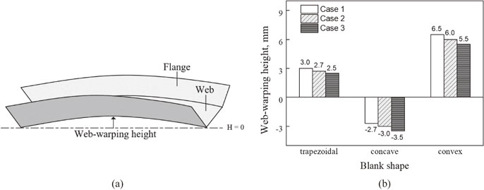
Fig. 5 (a) Measurement of web-warping, (b) experimental web-warping heights.
During the roll forming process, an initial metal blank is transformed into the desired profile with continuous bending through a series of forming rolls. The conventional roll forming process is available to manufacture the parts of constant profile with long length in large quantities at high production rates.1,2) However, in many industries such as the automotive industry, ship construction, and aerospace engineering, demands for the parts with variable profile has been increased to reduce the weight and increase functionality.3–9)
Flexible roll forming is a new forming process that allows the manufacture of parts with a variable profile. In this process, the rolls are not fixed at their position but can move both axially and rotationally along a trajectory so that can produce parts with the variable profile. During flexible roll forming, metal blanks are subjected to three-dimensional deformation such as transverse bending and other redundant deformations which includes inhomogeneous elongations or contraction at the blank. These redundant deformations can cause shape defects, such as camber, web warping, twist, and wrinkling.10–12) Previous research has investigated the effect of the longitudinal strain of strip edge during flexible roll forming process on defects such as bow and edge wave. Woo et al. characterized the degree of web-warping for different blank shapes and materials.13–15) They introduced the leveling roll to reduce the web-warping during the flexible-roll-forming process. Their result showed that the web-warping can be reduced by applying the leveling roll. Safdarian and Moslemi Naeini investigated the effects of the roll forming parameters of a channel section on the web-warping and longitudinal strain.16) Their result showed that peak longitudinal strain at the edge increases with increasing bending angle increment, strip thickness, however, the friction coefficient and speed of the roll do not have any effect on the longitudinal strain at the edge. Kasaei et al. investigated wrinkling limits in the flexible roll forming process using the experimental and numerical simulation.17) They predicted the occurrence of flange wrinkling in variable cross-sectional profiles via the combined evolution of the effective strain and stress triaxiality. Groche et al. developed an analytical one-step model to produce wrinkling-free parts with flexible roll forming.18) Their model is semi-empirical and based on plate-buckling mechanics to investigate the feasibility of new profile geometries without wrinkling. Wiebenga et al. studied bowing and springback defect in advanced high strength steel with V-shaped sections using a robust optimization method based on experiment and numerical analysis.19) Bowing and springback defects are reduced with the decreasing gap between forming rollers in each stand. Paralikas et al. introduced an optimization procedure for the roll forming process.20) They investigated the effect of distance between forming stands, forming rate, the gap between roller pairs in each stand, and roller diameter on the shear and longitudinal strains that occur on the flanges of products. Their result showed that the inter-distance between two successive stands and the gap between roller pairs in each stand is most effective for improving the quality.
Most previous studies have focused on the effect of the vertical roll gap on shape defects of the roll-formed part. However, the studies on the effect of the flange and web gaps on shape defects were generally lacking and scarce. Therefore, the effect of the flange and web gaps on shape defects in flexible roll forming process was experimentally investigated in this study. We investigated web-warping and longitudinal strain for three different blank shapes at various combinations of setup roll gaps.
Experiments were carried out using the laboratory-scale flexible roll forming machine shown in Fig. 1(a). Accurate roll gap control directly affects the product quality and operational performances.21–25) To obtain reproducible data, we ensured that the forming machine consisting of the forming roll stand and leveling roll stand was precisely operated. The leveling roll stand assists the blank to move straight without interfering with the motion of the forming roll. The forming and driving rolls are driven by a DC motor. The driving rolls feed the blank into the forming roll stands. The forming roll stand is connected to a screw shaft which is controlled by a servo motor so that the forming roll stands move and rotate according to a variable roll trajectory as shown in Fig. 1(b).

(a) Lab-scale flexible roll forming machine and (b) schematic of roll movement.
The bland was fed to the forming roll stand at a speed of 4.6 mm/s by the driving roll, and the forming roll had a 30° bending angle. We used three different blanks with trapezoidal, convex, and concave shapes with a 0.8 mm thickness in the experiments as shown in Fig. 2(a). Test material was SPCC mild steel with a Young’s modulus of 207 GPa, a yield strength of 170 MPa, an ultimate tensile strength of 339 MPa, and an elongation of 33.2%.

(a) Dimensions of the three different blanks: trapezoidal, concave, convex and (b) the flange and the web gap.
To investigate the effect of roll gaps on the flexible roll forming process, we controlled the flange and web gaps as shown in Fig. 2(b). The web gap can be controlled from 0 mm to 2 mm by changing the vertical position of the upper forming. To control the flange gap, a urethane ring was introduced to the forming roll shaft as shown in Fig. 2(b) so that the horizontal position of the upper roll could be controlled until the urethane ring could be compressed. The three combinations of setup roll gaps implemented in this study are summarized in Table 1.

To better understand the flexible roll forming process, the longitudinal strain history at the edge was measured experimentally via a resistance strain gauge. A strain gauge was mounted at the edge of the blank, and the strain was measured using the data logger and notebook computer as shown in Fig. 3.

Experiment setup for measurements of longitudinal strain.
Figure 4 shows the formed blanks obtained from the flexible roll forming experiments. As shown in the figures, there was a web-warping defect but no wrinkling. To investigate the web-warping at various setup roll gaps quantitatively, we defined the web-warping height as the maximum deviation in the height of the web area over the length of the profiles as shown in Fig. 5(a). Figure 5(b) shows the web-warping heights obtained from experiments. This result indicates that Case 1 increased the web-warping height while Case 3 decreased the web-warping height.

Experimental result; (a) trapezoidal, (b) concave, (c) convex blanks.

(a) Measurement of web-warping, (b) experimental web-warping heights.
During flexible roll forming, the flange zone needs to be longitudinally stretched in the concave blank and compressed in the convex blank for a flat web part.26,27) The required strains can be calculated via eqs. (1) and (2) as shown in Fig. 6.
| \begin{equation} \varepsilon_{\textit{convexblank}} = \ln \left(\frac{R'_{1}}{R_{1}} \right)\frac{\theta_{\textit{bend}}}{90^{\circ}},\quad R'_{1} = R_{1} - F \end{equation} | (1) |
| \begin{equation} \varepsilon_{\textit{concaveblank}} = \ln \left(\frac{R'_{2}}{R_{2}} \right)\frac{\theta_{\textit{bend}}}{90^{\circ}},\quad R'_{2} = R_{2} + F \end{equation} | (2) |

Schematics of (a) convex blank and (b) concave blank.
According to eq. (1) and eq. (2), the required analytical longitudinal strains are −0.00391 for the convex blank and 0.00387 for the concave blank; F is 35 mm; R1 and R2 are 3000 mm, and θbend is 30°. If the required longitudinal deformation is insufficient, different web-warping can occur to compensate for the required deformation so that the concave blank bends downward, whereas the convex blank bends upward as shown in Fig. 7.

Schematics of (a) downward and (b) upward web-warping.
Figure 8 shows the longitudinal strain history of three different blank shapes with different roll gap setups. Peak longitudinal strains for cases 1, 2 and 3 are 7.7 × 10⁻³, 6.1 × 10⁻³, 6.0 × 10⁻³ for a trapezoidal blank, 8.4 × 10⁻³, 6.9 × 10⁻³, 7.0 × 10⁻³ for a concave blank and 6.4 × 10⁻³, 5.5 × 10⁻³, 5.5 × 10⁻³ for a convex blank. This result indicates that a smaller flange gap induced an excessive longitudinal strain at the edge and causes web-warping. In the case of smaller web gap, the peak longitudinal did not change significantly, but the web-warping decreased. A smaller web gap induced longitudinal strain at the web part, which decreased the non-uniformity of the transversal distribution of the longitudinal strain and resulted in reduced web-warping. A previous study reported that as long as the roll gap was larger than the nominal material thickness, the material was only bent between the rolls, but for a smaller roll gap, the material was coined between the rolls. Due to the coining effect, the bottom part was elongated and web-warping was reduced.19)

Longitudinal strain history at the edge with different roll gap setup of (a) trapezoidal, (b) concave, and (c) convex blanks.
We experimentally investigated the effects of flange and web gaps on shape defects and made the following conclusions:
This research was supported by Basic Science Research Program through the National Research Foundation of Korea (NRF) funded by the Ministry of Education (No. 2016R1D1A3B03931174).