Abstract
Alternating and one-way tool paths were applied for penetrating tool friction stir incremental forming to compare the forming limit in height without sheet fracture. A truncated cone was formed using 200 mm × 200 mm × 2 mm commercial pure aluminum (JIS: A1050-O) sheets. After the cone was formed, the forming limits in height when employing penetrating tool friction stir incremental forming with alternating tool paths were compared with those formed with one-way tool paths. A tool rotation rate for forming of 1000 rpm, tool feed rate for forming of 1000 mm/min, and wall angle of 45° were used. The forming limit in height with alternating tool paths was approximately 30 mm and the limit in height for one-way tool paths was less than 10 mm. Volume change per unit length in radial direction for both formed sheets with alternating and one-way tool paths were calculated such that the improvement of forming limit in height could be examined. The volume change per unit length observed with alternating tool paths was smaller than for that with one-way tool paths, which means that a more uniform material distribution was achieved when penetrating tool friction stir incremental forming was employed with alternating tool paths.
1. Introduction
In recent years, market requirements for sheet metal have shifted from mass production of a few varieties to producing small batches of larger varieties. Not only have these demands varied, but a shorter lead time is also required. The cost and time required for preparing dies and punches are far too high for conventional press forming to satisfy those requirements. Various dieless forming methods, such as spinning, incremental forming, laser forming, peen forming, etc., have been developed in an effort to combat these problems.1–4) In all these dieless forming methods, incremental forming has received relatively high attention owing to its simple tooling and high formability.5,6) Single point incremental forming is a variant of incremental forming.7,8) In single point incremental forming, sheets are deformed locally by a hemispherical ended tool, and then formed into an objective shape incrementally by moving the tool along the contour lines of the objective shape. Because the tool deforms the sheets from one side, only bulgy shapes (concave or convex) can be formed by single point incremental forming. The forming of concave–convex mixed shapes is difficult to manufacture by conventional incremental forming methods.
Two main variants of incremental forming have been proposed9–11) for forming concave–convex mixed shapes. The first is two-point incremental forming using a support or half die, and the other is double-sided incremental forming that employs two tools to form sheets from both sides simultaneously. Both forming methods can form sheets into concave–convex mixed shapes, however, a half die is required for two-point incremental forming and a special forming machine with two tools on both sides of the sheet is required for double-sided incremental forming. If concave–convex mixed shapes could be formed with a common 3-axis NC milling machine without dies or supports, incremental forming could be used for various applications.
Jiang et al. combined single point incremental forming with bobbin tool friction stir welding,12) and suggested a new type of forming process for concave–convex mixed shapes called penetrating tool friction stir incremental forming (PTFSIF) as shown in Fig. 1.13) In PTFSIF, a penetrating tool with a large radius corner, using a conventional bobbin tool, can travel freely in the sheet metal without leaving any defects in the sheet. Concave–convex shapes can be formed using the top and bottom tools, respectively. No specific machine or die are required in PTFSIF.

However, the forming limit in height in PTFSIF is relatively small, less than 10 mm.13) The material flow from the advancing side (AS) to the retreating side (RS) causes a poor forming limit in height. The AS is the side at which the tool rotation and traveling direction are the same, and the RS is opposite.14) In the previous work,13) PTFSIF employed only a one-way tool path (OTPs), and the direction of the tool path did not change during forming, with a tool path direction of either clockwise (CW) or counterclockwise (CCW). In the forming with OTPs, positional relationship between AS and RS in the sheet does not vary during the forming, and direction of material flow is unidirectional, thus a groove-like defect is induced due to lack of material in AS. If the material flows bidirectionally in the sheet, a uniform volume distribution may be achieved, considerably improving forming limit in height. According to the definition of AS and RS, bidirectional material flow can be realizing using alternating tool paths (ATPs), in which the direction of the tool path was alternated in every forming circle path.
This study aims to improve the forming limit in height, PTFSIF with ATPs and OTPs, and the volume changes after forming were calculated to examine the results of forming limit in height. In addition, formable working conditions were investigated. Finally, forming of concave–convex mixed shapes which is the motivation of development PTFSIF were conducted by PTFSIF with the ATP.
2. Experimental Method
A 3-axis machining center (Okuma Corp., MILLAC44VII) was used for experiment of PTFSIF. An originally developed separable penetrating tool made of stainless steel (JIS: SUS304) as shown in Fig. 2 was used for separating the formed sheet from the tool after forming. A probe of right-thread and CW tool rotation direction were employed.
Commercial pure aluminum (JIS: A1050-O) sheets were used for the workpiece with the size of 200 mm × 200 mm × 2 mm. Figure 3 shows the experimental apparatus. A workpiece was placed on a table with a square hole, and clamped by blank holder and bolts. A hole located in the lower left corner of table was drilled and then the location of the penetrating tool was adjusted in the Z direction before forming.
Sheets were formed into convex shapes with a truncated cone having a bottom diameter of 140 mm, a wall angle of θ = 45° and a height of h = 50 mm. Two types of OTPs, with a tool path of CW and CCW, and two types of ATPs, with a tool path of CW+CCW and CCW+CW were used and forming limits in height with OTPs and ATPs were then compared. A tool path of CW+CCW means that direction of the tool path in the first forming circle was CW and the next was CCW. A tool path of CCW+CW means that the direction of the tool path in the first forming circle path was CCW and the next one was CW.
Figure 4 shows a tool path of CW+CCW. This tool path can be divided into two sections. One is the tool path for guiding, as shown as a dotted line in Fig. 4(a), and the other one is the tool path for forming, as shown as a solid line in Fig. 4(a). The tool rotation and feed rates in the tool path for guiding were set at a fixed value for tool stir-in the workpiece. After passing through the guiding path, tool rotation and feed rates were varied to tool rotation rate for forming of ωf, and tool feed rate for forming of vf for investigating formable working conditions. In this work, the following values were considered: tool stir-in the workpiece at a tool rotation rate for guiding of ωg = 1000 rpm and tool feed rate for guiding of vg = 200 mm/min. Further, contour-based tool path strategy was used. In Fig. 4, a sheet was formed with the tool path of CW in contour tool path, and then the tool was moved to the neighbor contour tool path and the sheet was formed with the tool path of CCW. The tool path between neighboring contours was named the connecting tool path in this study. In the connecting tool path, the tool was then moved to the inner contour in radial direction for pitch in radial direction pr and then moved up for pitch in Z direction pz as shown in Fig. 4(b). From the preliminary experiments, the tool feed rate for connecting neighboring contours vc was set to 200 mm/min to avoid the sheet fracturing at the connecting part. Pitch in Z direction pz was 0.5 mm. Forming was terminated when sheet or tool fractured during the forming, and the height at which sheet or tool fractured was defined as forming limit in height, hlim.
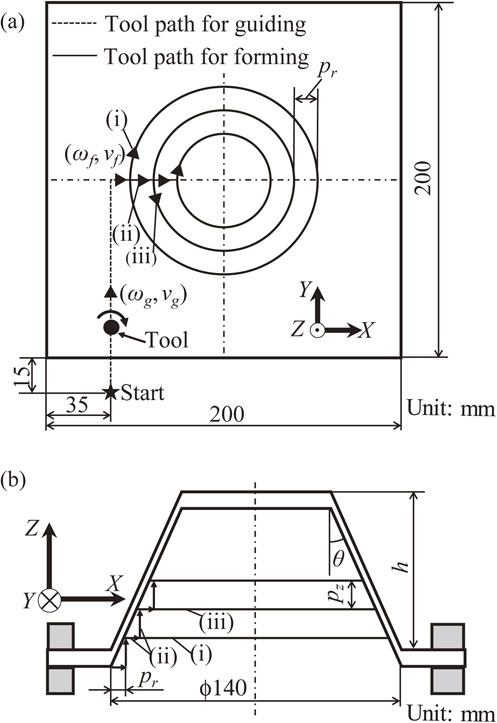
Figure 5 shows the variation in sheet thickness with ideal incremental forming. t0 is initial sheet thickness; t1 is sheet thickness of formed sheet; and tz is thickness in Z direction of formed sheet, which was defined as a length between two points in top surface and bottom surface of formed sheet at the same x and y coordinates. Although tz and t0 are equal at any formed part because of only shearing conditions, tz and t0 are not equal due to the non-uniform volume distribution. The difference between tz and t0 can be used as an indicator for estimating the variation in volume with Z direction. Volume change per unit length considering volume change not only in Z direction but also in circumferential direction was introduced to estimate the volume change. δv(r) is volume change per unit length at position r and calculated by eq. (1).
| \begin{equation}
\delta_{v}(r) = (t_{z}(r) - t_{0})\times 2\pi r
\end{equation}
| (1) |
where
r is distance from central axis of the truncated cone to measured point in radial direction.
tz(
r) means thickness in
Z direction at position
r. In this study, the sheet was cut in half by wire electrical discharge machining and thickness in
Z direction of formed sheet were measured using the sectional profile photos via image processing software. For comparing the amount of volume change with ATPs and OTPs, variance of distribution of volume change per unit length, σ
2 was calculated in
eq. (2).
| \begin{equation}
\sigma^{2} = \int_{r_{1}}^{r_{2}} \frac{(\delta_{v}(r) - \overline{\delta_{v}})^2}{|r_{2} - r_{1}|}dr
\end{equation}
| (2) |
In eq. (2), r1 and r2 are the lengths from the center of the cone to start and end measured points, respectively. $\overline{\delta _{v}}$ is average value of δv(r) from r = r1 to r2.
3. Results and Discussions
3.1 Experimental reliability and repeatability
In OTPs, only one type of fracture morphology caused by groove-like defects appeared under the same forming conditions. In ATPs, another fracture caused by larger upheaval in the center also appeared under the same forming conditions and both fractures occurred randomly. In a research on the probability of each defect, experiment under the same forming conditions was conducted 36 times, and number of fractures caused by groove-like defect and fractures caused by upheaval in center were 23 and 13, respectively. Thus, probability of fractures caused by groove-like defect and fractures caused by upheaval in center were 63.9% and 36.1%. Figure 6 shows sheets without fracture, fractures caused by groove-like defect, and those with larger upheavals in the center.

For all fractures caused by groove-like defects, sheets fractured from the area of connecting tool path as shown in Fig. 6(b); for those caused by larger upheaval in the center, the upheaval in the center became larger as forming proceeded, as shown in Fig. 6(e), and then fractures progressed to the lower part in the sheet as shown in Fig. 6(c).
The fact that the two fracture morphologies occurred randomly in the PTFSIF with ATPs in the same forming conditions indicated that experimental reliability of PTFSIF with ATPs is not high, however, experimental repeatability of the same fracture morphology is high. For example, under forming conditions of tool path of CW+CCW, θ = 45°, ωf = 1000 rpm, vf = 1000 mm/min, results of forming limit in height hlim for three times experiment were 30, 28.5 and 28 mm, respectively in fracture caused by groove-like defect. Under the same forming conditions, three results of forming limit in height in fracture caused by upheaval in center were 20, 18.5 and 19 mm, respectively. Because the difference among the three results under the same fracture morphology were not large, the experimental repeatability of this experiment is considered to be high.
Although the formation of fractures caused by groove-like defects can be explained by the material flow between AS and RS, which has been verified in the previous study,13) the reason for the formation of fractures caused by larger upheaval in the center is still unknown. In the following sections, only experimental results of fracture caused by groove-like defect were used.
3.2 Forming limits in height
Figure 7 compares the forming limits in height with ATPs and OTPs. Each experiment was conducted three times under the same conditions, and the average value of forming limits in height was plotted. The error bars express the maximum and minimum values. The forming limits in height with ATPs were approximately 30 mm and those with OTPs were lower than 10 mm. Compared with OTPs, forming limit in height with ATPs was drastically improved, with an almost 200% increase of forming limit in height. In ATPs, forming limit in heights with tool path of CW+CCW and CCW+CW were almost the same. Forming limit in height with a tool path of CW was the lowest. This can be explained by the unidirectional material flow from the outer part of sheet (AS) to the inner part of sheet (RS). Excessive material in the inner part made the sheet difficult to deform because the tool forms sheets from outer to inner side.

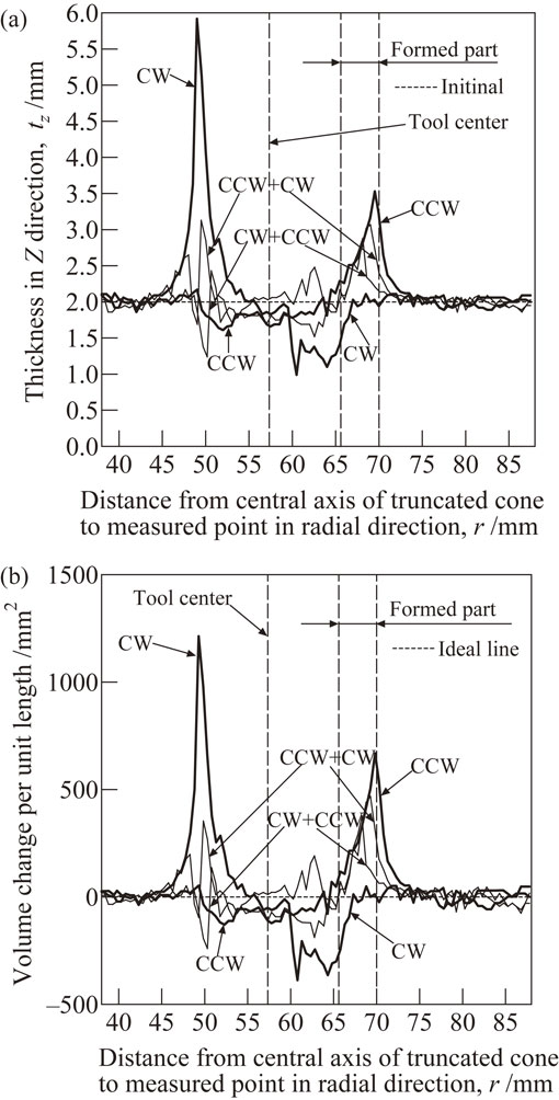
Figure 8 shows the schematic of definition of three areas in the formed sheet for investigating material flow. The formed sheet was divided into three parts: the formed, tool corner, and tool shoulder parts. The formed part is the area from the beginning of the forming point to the theoretical contacting point, the location of which can be determined by wall angle, θ. The tool corner part is the area from the forming theoretical contacting point to the edge of the tool shoulder. The tool shoulder part is defined as the area of the flat part of the penetrating tool. Figure 9 shows the distributions of thickness in Z direction tz and volume change per unit length in radial direction obtained with ATPs and OTPs. The forming conditions were θ = 45°, ωf = 1000 rpm, vf = 1000 mm/min and a height of h = 6 mm. The thick lines are results with OTPs and the thin lines are those with ATPs. The dotted line in Fig. 9(b) is an ideal line of volume change per unit length, which is constant to zero because tz = t0 in ideal conditions. The formed part and tool center were also marked in the figure. Thickness in Z direction and volume change per unit length with ATPs were smaller in absolute value than those with OTPs at the formed part. The fluctuation of distribution with ATPs was smaller than those with OTPs.
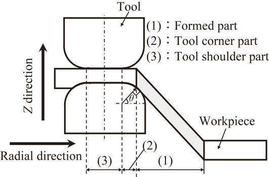
Figure 10 compares the variances of volume change per unit length σ2 with ATPs and OTPs. σ2 with ATPs was smaller than that with OTPs. As σ2 means the average of variation in volume following forming, a slight variation in uniform volume distribution leads to a considerable increase in the forming limit in height. Thus, the results of σ2 with ATPs and OTPs correspond to those of forming limits in height in Fig. 7.
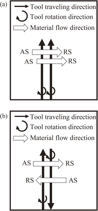
Figure 11 shows the schematic illustration of material flow with ATPs and OTPs. As the positional relationship between AS and RS does not vary in two forming tool paths of neighboring contours in OTPs, the direction of material flow does not vary in OTPs. In contrast, as positional relationship of AS and RS alternates in two forming tool paths of neighbor contours, the direction of material flow alternates in ATPs. Therefore, the variance of volume change per unit length with ATPs was smaller than that with OTPs.
From those results, forming limits in height were improved with ATPs; this improvement can be attributed to material flow. As the variance σ2 of CW+CCW is the smallest in the four types of tool paths used, the following experiments regarding formable working conditions and thickness of formed sheet were conducted using only the tool path of CW+CCW.
3.3 Formable working conditions
Wall angle θ, tool rotation rate for forming ωf, and tool feed rate for forming vf, were varied for determining the formable working conditions using tool path of CW+CCW. Figure 12 shows formable tool feed and rotation rates for forming in PTFSIF at a wall angle of θ = 50°. Open circle marks mean the forming was completed without sheet or tool fracture until forming height of h = 30 mm. Cross marks mean the sheet was fractured during the forming. Open triangle marks mean the tool fractured during the forming. Formable working conditions are surrounded by the failed ones, and this indicates that there are suitable combinations of tool rotation rate and tool feed rate in PTFSIF. This tendency is same for that of friction stir welding and friction stir incremental forming.15) The absolute values of formable tool feed and rotation rates for forming in PTFSIF are smaller than those of conventional friction stir incremental forming. This is because two shoulders were used for generating frictional heat and plastic flow of materials caused by the probe also generate the heat. In conventional friction stir incremental forming, friction stirring occurs from a relatively high value of tool rotation rate. The tool rotation rate is too small to generate sufficient frictional heat, and this is indicated by the open triangle marks located in the bottom of the formable region.

Next, the tool rotation rate for forming was fixed to ωf = 1000 rpm and the tool feed rate for forming was varies, and the formable wall angle was investigated. Figure 13 shows the formable wall angle in PTFSIF with a tool path of CW+CCW. Open circle marks mean that the forming was completed without fracture until a height of h = 30 mm. Cross marks mean the sheet was fractured during the forming. Comparing with conventional friction stir incremental forming, the range of the formable tool feed rate for forming from vf = 800–1800 mm/min was narrow. In the formable working conditions, the relationship between the tool feed rate for forming and the minimum formable wall angle was similar to a V-shape. This result indicates that optimal tool feed rate for forming exist for the minimum formable wall angle.

Figure 14 shows the relation between the wall angle and forming limit in height with tool paths of CW+CCW and CCW. The closed circles depict the results with a tool path of CW+CCW and the open circles represent a tool path of CCW. The forming conditions were a tool rotation rate for forming of ωf =1000 rpm and a tool feed rate for forming of vf = 1000 mm/min. The objective height was h = 30 mm. Forming limits in heights with a tool path of CW+CCW were larger than those with a tool path of CCW. When the wall angle varies from 20° to 45°, the forming limit in height with a tool path of CW+CCW increased. The forming limit in height was 30 mm when the wall angle varies from 45° to 60°, which is the objective height. Although the forming limit in height also increased with increasing the wall angle from 20° to 45° with a tool path of CCW, it decreased when wall angle varied from 45° to 60°. The variation in forming limit in height with a tool path of CCW was very small. The increase of the forming limit in height with increase of the wall angle means forming was difficult in a small wall angle, which corresponds to the conventional incremental forming and friction stir incremental forming.16)
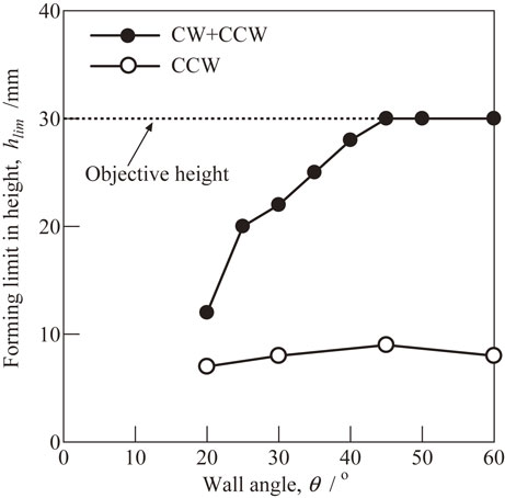
Figure 15 shows the thickness distribution of a sheet formed in PTFSIF with a tool path of CW+CCW. Forming conditions were ωf = 1000 rpm, vf = 1000 mm/min, θ = 45° and h = 20 mm. The solid line indicates the measured thickness, and the dotted line indicates the ideal thickness, which were calculated by the sine law without considering the tool size. The curve of measured thickness was divided into three areas as well as shown in Fig. 8. From the results, thickness of formed part in the beginning were larger than the initial sheet thickness. The thickness of the formed sheet decreased in the initial part and then stabilized at a value which is very near to the ideal thickness, and a uniform volume distribution was achieved.
3.5 Forming of concave–convex mixed shapes
Forming of concave-convex mixed shapes with ATPs were conducted after forming limit in height was improved in penetrating tool friction stir incremental forming. The objective shapes of concave–convex mixed comprises concentric concave and convex truncated cones. Figure 16 shows the dimensions of the objective concave–convex mixed shapes. The forming tool path was CW+CCW. The forming conditions were ωg = 1000 rpm, ωf = 1000 rpm, vg = 200 mm/min, vc = 200 mm/min and vf = 1000 mm/min. Pitch in Z direction was pz = 0.5 mm. In both forming of concave–convex mixed shapes and convex–concave mixed shapes, the sheets did not fracture until the forming had finished. Figure 17 shows the profiles of formed concave–convex and convex–concave mixed shapes. The ideal shapes and formed shapes are different at the center part and the connecting part which connected the concave shape to convex shape. The difference at the connecting part was caused by the alternated forming direction during the forming.
4. Conclusions
It is confirmed that alternating tool paths can improve forming limit in height in PTFSIF. The first step was to form a truncated cone from A1050-O sheets having size of 200 mm × 200 mm × 2 mm. The results of forming limits in height using alternating tool paths and one-way tool paths were compared. Formable working conditions were also investigated. The thickness of the formed sheet in penetrating tool friction stir incremental forming with alternating tool paths was measured. The following conclusions were drawn:
-
(1)
In forming with alternating tool paths, two types of fracture morphologies, fractures caused by groove-like defects and large upheavals in the center, occurred randomly under a few forming conditions. The experimental repeatability of the same fracture morphology is high.
-
(2)
The forming limit in height using alternating tool paths demonstrates a drastic improvement over using one-way tool paths, achieving an approximately 200% increase in forming limit in height. This is due to material distributed more evenly both inside and outside of the forming region.
-
(3)
Compared with conventional friction stir incremental forming, the formable working conditions were narrow. This was observed because two shoulders were used for generating frictional heat and plastic flow of materials caused by the probe generate the heat in penetrating tool friction stir incremental forming.
-
(4)
Concave–convex mixed shapes were formed successfully by penetrating tool friction stir incremental forming with an alternating tool path.
REFERENCES
- 1) O. Music, J.M. Allwood and K. Kawai: J. Mater. Process. Technol. 210 (2010) 3–23.
- 2) J. Jeswiet, F. Micari, G. Hirt, A. Bramley, J. Duflou and J. Allwood: CIRP Ann. 54 (2005) 88–114.
- 3) F. Cook, D. Celentano and R. Jorge: Int. J. Adv. Manuf. Technol. 86 (2016) 2187–2196.
- 4) H.Y. Miao, D. Demers, S. Larose, C. Perron and M. Levesque: J. Mater. Process. Technol. 210 (2010) 2089–2102.
- 5) M. Shim and J. Park: J. Mater. Process. Technol. 113 (2001) 654–658.
- 6) Y.H. Kim and J.J. Park: J. Mater. Process. Technol. 130–131 (2002) 42–46.
- 7) Y.L. Li, X.X. Chen, Z.B. Liu, J. Sun, F.Y. Li, J.F. Li and G.Q. Zhao: Int. J. Adv. Manuf. Technol. 92 (2017) 2439–2462.
- 8) G. Buffa, D. Campanella and L. Fratini: Int. J. Adv. Manuf. Technol. 66 (2013) 1343–1351.
- 9) H. Amino: J. Jpn. Soc. Technol. 51 (2010) 1119–1123 (In Japanese).
- 10) A. Attanasio, E. Ceretti, C. Giaradini and L. Mazzoni: J. Mater. Process. Technol. 197 (2008) 59–67.
- 11) B. Lu, Y. Fang, D.K. Xu, J. Chen, S. Ai, H. Long, H. Ou and J. Cao: Int. J. Mach. Tools Manuf. 93 (2015) 37–48.
- 12) W.Y. Li, T. Fu, L. Hutsch, J. Hilgert, F.F. Wang, J.F. Santos and N. Huber: Mater. Des. 64 (2014) 714–720.
- 13) W. Jiang, T. Miura, M. Otsu, M. Okada, R. Matsumoto, H. Yoshimura and T. Muranaka: Mater. Trans. 60 (2019) 2416–2425.
- 14) Japan Welding Society: Friction Stir Welding, (Sanpo Pub., Tokyo, 2006) p. 15 (In Japanese).
- 15) M. Otsu, H. Matsuo, M. Matsuda and K. Takashima: Steel Res. Int. 81 (2010) 942–945.
- 16) M. Otsu, T. Ichikawa, M. Matsuda and K. Takashima: Steel Res. Int. Special Eds. (2011) 537–541.
Nomenclature
ωfTool rotation rate for forming
vfTool feed rate for forming
ωgTool rotation rate for guiding path
vgTool feed rate for guiding path
vcTool feed rate for connecting to neighbor contour
prPitch in radial direction
pzPitch in Z direction
hHeight of objective shape
hlimForming limit in height
rDistance from center axis of truncated cone to measured point in radial direction
δv(r)Volume change per unit length at position r
$\overline{\delta _{v}}$Average of volume change per unit length
σ2Variance of volume change per unit length
θWall angle
t0Initial sheet thickness
t1Sheet thickness of formed sheet
tzThickness in Z direction of formed sheet
tz(r)Thickness in Z direction of formed sheet at position r