1. Introduction
Several kinds of austenitic stainless steels (SSs) used in pressurized water reactor (PWR) nuclear power plants as key components due to their outstanding machinability, corrosion resistance, and mechanical properties.1–8) Almost all components are subject to surface machining such as milling, turning and grinding before use. However, the crystal structure was often damaged during surface machining. Furthermore, the formation of oxide film on machined surface can be affected when immersed in high temperature water environment.4,9–13) As a result, stress corrosion cracking (SCC) was easy occurred due to the formation of poor quality oxide film on machined specimens.4,14–18)
The oxide film formed on the surface of stainless steel has crucial effect on the corrosion resistance in high temperature water. Several previous studies indicated that corrosion resistance was improved when an integrated, compact and thick Cr rich oxide film was formed on specimen surface.1,10,19–21) The oxide film formed on a machined specimen surface was different from that on a finely prepared surface. Sarata et al.4) indicated that the oxide film was thicker on mechanically polished 304L SS specimens than grinded specimens when exposed in 340°C high temperature water environment. Han et al.10,12) indicated that the corrosion resistance of oxide film formed on a colloidal silica slurry polished surface was better than an electrolysis polished surface of 316L SS in 320°C high temperature water environment. As known to all, milling was one common surface machining technology that causes a more serious damaging effect on surface integrity than polishing or grinding.22–24) However, the effect of milling on the oxide film of 304L and 316L SSs is not yet clear now. As for high safety requirements, it is necessary to study the oxidation property of 304L and 316L SSs which are widely used in high temperature water environment.
In the present study, the effect of machining on the oxide film of 304L and 316L SSs in 300°C high temperature water was investigated. The composition and structure of the oxide film was analysed. The diffusion mechanism of Cr and Ni during oxidation was studied. Furthermore, the effect of milling operation on corrosion resistance of oxide film was investigated by electrochemical workstation.
2. Experimental
2.1 Materials
Table 1 shows the chemical compositions of 304L and 316L SSs used for the present study. The two kinds of SSs were manufactured by hot rolling followed by solution treatment at 1100°C for two hours.

Table 1 Chemical composition of 304L and 316L SSs (wt.%).
The milling operation parameters were shown in Table 2, and corresponding milled specimens were marked C1 and D1 for 304L and 316L SSs respectively. The mechanically polished specimens of the two kinds of SSs were marked C0 and D0 respectively, used as the reference group. After oxidation in 300°C high temperature water environment, each specimen was marked as previous reference number followed by oxidation time (days). For example, C110 means specimen C1 oxidized for 10 days.

Table 2 Milling parameters for tested specimens.
The oxide film tests were carried out in a static autoclave to simulate the pressurized water reactor (PWR) environment. All the polished specimens were prepared by grounding with silicon carbide paper up to 1200 grit then polishing with 1.5 µm diamond paste. The machined specimens were prepared according to the milling parameters in the Table 2. All specimens were immersed in 300°C high temperature water. The water chemistry parameters were shown in Table 3. After immersion test, parts of specimens were examined by X-ray photoelectron spectroscopy (XPS). The main XPS peaks were fitted through the XPSPEAK4.1 software to get subsidiary peaks. The background subtraction was obtained by Shirley type.19,25) The quantitative evaluations of all species were distinguished based on their binding energies (BEs) referenced in the NIST X-ray Photoelectron Spectroscopy Handbook.26) The constituent compositions at different depths of oxide film were measured by different XPS sputtering times. The rate of XPS sputtering was 0.2 nm/s (vs. Ta2O5). The surface analysis was 0 s for sputtering time.

Table 3 High temperature water chemistry for immerse test.
The chemical compositions of cross-sections of the oxide film on specimens were analysed by electron probe micro-analyser (EPMA). Nickel plating was covered on the specimen surface to protect the oxide film before the EPMA analysis. The microstructure of the oxide film was observed by transmission electron microscopy (TEM). The chemical compositions of the oxide film were measured by energy dispersive X-ray spectrometer (EDS). TEM observation was performed in a Tecnai F20 type microscope operated at 200 kV. The TEM specimens were prepared by focused ion beam (FIB).
2.4 Electrochemical test
The corrosion resistance of the oxide film were evaluated by electrochemistry methods. All tests were conducted using an electrochemical (Salarton, 12608W) workstation connected to a three-electrode cell. The reference electrode was a saturated calomel electrode (SCE), and a platinum plate was used as auxiliary electrode. The scan rate of the tafel tests were 20 mV/min. The electrochemical impedance spectroscopy (EIS) tests were conducted under frequency range of 0.01–100000 Hz. The EIS test results were analysed by the ZSimpWin software. All electrochemistry tests were conducted in a 3.5 wt.% NaCl solution at 25°C.
3. Results and Discussion
3.1 Morphology and XPS results of oxide film
An oxide film with complex constituent compositions and structure can be formed when SSs immersed in high temperature water.1,27–30) The corrosion resistance can be improved if the oxide film was compact and complete, while the protective properties were poor if the oxide film was loose or incomplete.4,10–12) Figure 1 shows the surface and cross-section morphologies of oxide film after immersion in 300°C high temperature water for 80 days of 316L SSs specimens. One can see that oxide particles were formed after immersion in 300°C water for 80 days, and the thickness of the oxide film were about 1 µm for two specimens.

Figure 2(a)–(d) shows the detailed XPS spectra of Fe 2p3/2, Cr 2p3/2, Ni 2p3/2 and Mo 3d3/2 of the surface oxide film tested in 300°C water environment for 20 days. One can see that the main peaks of Fe 2p3/2, Cr 2p3/2, Ni 2p3/2 and Mo 3d3/2 were positioned at approximately 710.3, 577.1, 856.6 and 232.4 eV respectively, which indicate the formation of FeOOH, Fe2O3 and FeO; Cr2O3, CrO3 and Cr(OH)3; Ni(OH)2; as well as MoO3 and MoO2. This indicates that Fe, Cr, Ni and Mo were all fully oxidized. The constituent compositions of the surface oxide film were similar to specimens immersed for 20 and 80 days. The oxide types between the polished and machined specimens were nearly identical.

Figure 3 shows the oxides of Fe formed at different depths in the oxide film after immersion in 300°C high temperature water for 80 days. One can see that the main peaks of the Fe 2p3/2 spectra sputtered for 200, 500 and 1500 s were positioned at approximately 712.01, 711.21 and 707.47 eV respectively, which indicated the formation of FeOOH, Fe2O3 and FeO; Fe2O3 and FeO; as well as FeO, Fe2O3 and Fe. This result indicates that the degree of oxidation decreased with increasing depth of the oxide film. Similar results were reported in Refs. 1), 19), 20), 27).

Figure 4 shows the XPS spectra results after sputtering for 2500 s of the specimen D1 after immersion in 300°C high temperature water for 80 days. One can see that the main peaks of Fe 2p3/2, Cr 2p3/2, Ni 2p3/2 and Mo 3d3/2 were positioned at approximately 710.5, 576.5, 852.7 and 231.7 eV respectively, which indicated the existence of FeO and Fe; Cr2O3 and Cr; Ni as well as Mo. This indicates that Fe, Cr, Ni and Mo were all incompletely oxidized at the depth of sputtering for 2500 s, and the matrix of the specimen was detected.

Figure 5 shows the EPMA line scanning results of polished and milled cross-sections of 304L and 316L SSs after immersion in 300°C high temperature water for 80 days. One can see that the significant change of the metal elements and oxygen were shown in the range of 900 nm for all specimens. The contents of Fe and O were decreased while the Cr, Ni and Mo were increased with increasing depth of the oxide film. This indicates that a Fe-rich oxide was formed in the surface, while the content of Cr increased with increasing depth of the oxide film. This result agrees with previous studies.4,10,11,20,30–32)
3.2 Microstructure of the oxide film
The selection of TEM specimens were cut by FIB, which considered both the surface condition and immersion time. The oxide film would be too thin to conveniently observe if the immerse time was too short. However, it would be very brittle and easy to fracture if the immersion time was too long. Therefore the specimens immersed for 20 days of 316L SS were selected. D020 stands for the specimen cut from area with uniform oxide particle distribution of polished sample. D120 stands for the specimen cut from area along the cutting line of milled sample.
Figure 6 shows the TEM morphologies of the D020 specimen. The cross-section of polished specimen was fully covered by the oxide film, as shown in Fig. 6(a). Figure 6(b) shows an enlarged morphology marked in Fig. 6(a). The oxide film including oxide particles, loose outer film and compact inner film can be clearly distinguished in Fig. 6(c). The thickness of inner film was about 50 nm.
Figure 7 is the EDS scanning result of the line shown in Fig. 6(c). The three layers of oxide film can be distinguished by contents of elements. The content of Fe was relatively higher in the loose outer film, which indicates that iron oxide was the main component. So the protection ability of the outer layer is poor.4,10,11,20) The inner layer film was compact and complete with a high content of Cr, which indicates better protective ability than the outer layer. It was worth noting that the content of Cr and Ni peaked at the interface of the oxide film and matrix, indicated with black circles in Fig. 7.

Figure 8 shows the TEM morphologies of the D120 specimen. Figure 8(a) shows the morphology seen from the cross-section. Figure 8(b) and (c) shows enlarged morphologies marked in Fig. 8(a). The oxide particles and loose film can be observed clearly. Only part of the area formed thin inner oxide film with thickness about 20–30 nm. Compared to the D020 specimen, the structural integrity of the oxide film of specimen D120 was worse, especially the inner oxide film.

Figure 9 is the EDS scanning result of the line marked on the cross-section of specimen D120. Similar to the D020 specimen, three layers of the oxide particles, loose outer film and compact inner film can be distinguished. However, the interfaces of adjacent layers are not clearly differentiated. The elemental composition showed dramatic fluctuation in oxide particles. This can be attributed to the holes existence. The chemical compositions of outer and inner layers were similar to the specimen D020. The loose oxide particles occupied about more than a half of the oxide film with thickness of about 50 nm. The content of Cr and Ni peaked at the interface of the oxide film and matrix, indicated in black circles of Fig. 9.

As mentioned previously, the Cr element can enrich at the interface between oxide film and matrix, as shown in Fig. 7 and Fig. 9. A schematic diagram explaining the Cr-rich layer on the cross-section of the interface shows in Fig. 10. During the process, O can diffuse to the interface and form oxides with a metal, as shown in Fig. 10(a). The Cr-rich oxides often form in the inner layer with the diffusion of the O, as shown in Fig. 10(b). However, the Cr is continually depleted as the oxidation process continues. For the purpose of sustaining the oxidation process, the Cr in matrix will diffuse to the interface and a layer of Cr-rich area will form, as shown in Fig. 10(c).

The oxidation dynamics of SS was found by Ziemniak et al.33) during their study of the oxidation behaviour of 304L SS in 260°C high temperature water environment. Their test result indicated that the outer and inner layers oxide film on 304L SS were mainly Fe-rich and Cr-rich oxides respectively after immersion for 10000 h. However, the atom ratio of Cr and Fe reached 7:3 in the inner oxide film, which is far beyond the ratio in 304L SS matrix. The theoretical basis of Cr diffusion can be described as the eqs. (1) and (2):34)
| \begin{equation}
C(z,t) = C_{0} + (C_{A} - C_{0})\text{erf}\left(\frac{z}{2\sqrt{D\cdot t}}\right)
\end{equation}
| (1) |
| \begin{equation}
\text{erf}(\text{x}) = \frac{2}{\sqrt{\pi}}\int_{0}^{x} e^{-\varphi^{2}}d\varphi
\end{equation}
| (2) |
where
C(
z,
t) is the Cr concentration at a distance z from the oxide/metal interface at time
t.
C0 is the concentration of Cr at the interface of the oxide and matrix metal.
CA is the bulk concentration of Cr.
D is the diffusion coefficient of Cr. This equation explains the segregation behaviour of Cr at the interface. A similar phenomenon of Cr segregation at the interface was also found in the oxidation behaviour of 316 SS conducted by Wang
et al.11)
3.3 Corrosion resistance of the oxide film
The Tafel tests were conducted of polished and milled specimens after immersion for 10 and 80 days. The corresponding corrosion current density calculated was given in Table 4. The corrosion current density decreased with increasing immersion time from 10 to 80 days for both surface conditions. A higher corrosion current density means a lower corrosion resistance. The results indicated that the corrosion current densities of milled specimens were higher than that of polished ones. These results are consistent with the structure of oxide film.

Table 4 Corrosion current density of 304L and 316L SSs calculated by tafel curve (A/cm2).
The EIS tests were conducted of polished and milled specimens after immersion for 10 and 80 days, respectively. According to the previous studies,1,10,19–21) the fitting circuit diagram was shown in Fig. 11. The specimens immersed for 10 days showed monolayer oxide film characteristics, while it presented double-layer oxide film characteristics after immersion for 80 days. The corresponding fitting circuit diagrams are shown in Fig. 11(a) and (b), respectively. The result fitted by EIS curve is shown in Table 5. One can see that the resistances of specimens immersed for 80 days were all higher than those immersed for 10 days. The resistances of the milled specimens were lower than polished ones. In a word, both EIS and Tafel results indicated the milling operation has a negative effect on the corrosion resistance for 304L and 316L SSs.
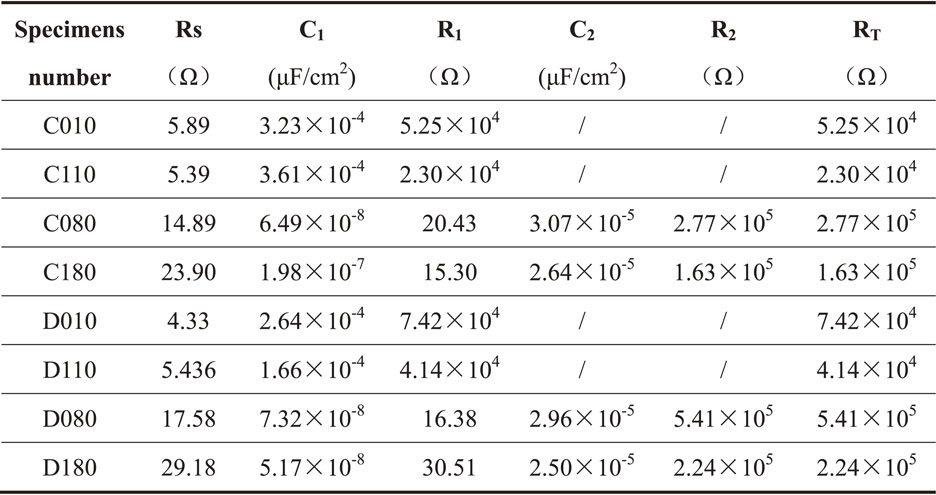
Table 5 Fitting results of EIS after immersion in 300°C high temperature water of 304L and 316L SSs.


