Abstract
In this study, we propose a simple approach to accelerate crack initiation in intergranular stress corrosion cracking (IGSCC) of Alloy 600 in a simulated pressurized water reactor (PWR) primary water environment. In addition, we perform three-dimensional crystallographic characterization of the crack initiation by electron backscatter diffraction (EBSD). Initiation of IGSCC of the alloy in the PWR primary environment was realized for a flat tensile specimen in a considerably short time through a slow strain rate test (SSRT). The accelerated initiation was attributed to the asperity of the alloy surface induced by mechano-chemical polishing with colloidal silica suspension before the SSRT was conducted. Following the SSRT, the specimen surfaces were covered with thick oxide films, which prevented EBSD measurements. The sputtering of thick oxide films enabled us to characterize cracks with EBSD, thus yielding important information on IGSCC. Finally, an approach for three-dimensional characterization of crack initiation is discussed.

1. Introduction
Alloy 600 is employed in pressurized water reactors (PWRs) for steam generator tubing and other structural materials. However, the alloy suffers from intergranular stress corrosion cracking (IGSCC). Therefore, the initiation and propagation of IGSCC in PWR primary environments have been investigated extensively.1–18) In addition, the effects of the microstructure, precipitate, and dislocation on the initiation and propagation of cracks have been studied by characterizing the alloy surface or substrate where cracks initiate and/or propagate using scanning electron microscopy (SEM), transmission electron microscopy (TEM), Auger electron spectroscopy (AES), energy dispersive X-ray spectroscopy (EDS), atom probe tomography (APT) and secondary ion mass spectroscopy (SIMS).1,2,5–7,10,16,18)
Electron backscatter diffraction (EBSD) is an SEM-based diffraction technique that provides crystallographic information of grains in crystalline materials. Thus, the technique has been widely applied to characterize, for example, the plastic strain of stainless steel and nickel-based alloys.19–21) It also has been recently adopted to characterize stress corrosion cracking of Alloy 600 in high-temperature water. Young et al. successfully obtained the grain boundary map, Euler angle image, and misorientation map around a stress corrosion cracking (SCC) crack generated on Alloy 600 in hydrogenated water at 360°C.11) Hou et al. also investigated the grain boundary map and Kernel average misorientation map near an SCC crack on Alloy 600 exposed to a corrosive solution consisting of sodium hydroxide, lead oxide, and pure water at 330°C. They explained that the high dislocation density and strain concentration induced by cold work promoted crack propagation.14) Both studies examined the cross-sections of the specimens and focused on crack propagation rather than on crack initiation. Although the SCC of Alloy 600 has been studied according to various aspects such as slip dissolution, internal oxidation and hydrogen embrittlement, the initiation of cracks has not been crystallographically examined. To the best of our knowledge, crystallographic evaluation of crack initiation on nickel-based alloys in high-temperature and high-pressure water environments has not been reported. In order to characterize the crystallographic features of the initiated crack, top-view observation is required. However, simulating IGSCC of Ni-based alloys such as Alloy 600 on the plane surface of a specimen is not easy. Furthermore, as the exposure of Alloy 600 to high-temperature water leads to the formation of relatively thick oxide layers on the alloy surface,22,23) clear diffraction patterns of the underlying substrate alloy cannot be acquired from EBSD measurements. We previously proposed a procedure to initiate intergranular cracks on the plane surfaces of Type 316L stainless steel and Alloy 600, and demonstrated that EBSD analysis could be performed on the surfaces.24)
Herein, the crystallographic approach based on EBSD measurements is presented in greater detail for Alloy 600 exposed to a simulated PWR primary water environment.
2. Experimental
The material examined was a 2-mm-thick Alloy 600 sheet, the chemical composition of which is listed in Table 1. The mill-annealed Alloy 600 sheet was cold-worked with a reduction rate of 10%. A tensile specimen with the gauge section of 4 mm wide by 2 mm thick and 10 mm long was cut from the sheet by using an electric discharge machine, and the specimen was mechanically ground with SiC abrasive papers up to #2000. This was followed by successive polishing with 9- and 1/4-µm diamond paste and mechano-chemical polishing with colloidal silica suspension for 20 min. The surface of the specimen was examined by Atomic Force Microscope (AFM) and Field Emission Scanning Electron Microscope (FE-SEM) after the mecho-chemical polishing.

Table 1 Chemical composition of Alloy 600 (mass%).
A slow strain rate test (SSRT) was performed on the Alloy 600 specimen in a simulated PWR primary water environment. A solution containing 500 ppm B and 2 ppm Li as H3BO3 and LiOH, respectively was controlled at a temperature of 633 K with a dissolved oxygen concentration of less than 1 ppb and dissolved hydrogen concentration of 0.5 ppm. Furthermore, the pressure of the solution was controlled at 20 MPa during the SSRT. This environment is often used to simulate a PWR primary side water. The tensile specimen was elongated in the environment up to a strain of 10% at a rate of 5 × 10⁻⁷ s−1 and was held under this strain for 50 h.
After the SSRT, the specimen was characterized by FE-SEM and EBSD. Prior to EBSD characterization, the surface of the specimen was sputtered by Ar+ ions to remove the thick oxide films formed in the PWR primary environment. An EBSD measurement was performed for an area of 250 × 250 µm2 with a step size of 1 µm on five locations at an accelerating voltage of 25 kV. In this work, the grain boundaries, where cracks initiated during the SSRT, were crystallographically analyzed. In order to perform the analysis, SEM images were captured at the same location at which EBSD was conducted. In the analysis, locations with misorientations greater than 15° (high-angle grain boundary) were defined as the grain boundary. In general, as cracks initiate and propagate inside a material along the grain boundary in IGSCC, crystallographic information of the grain boundary inside the material is required to better understand IGSCC. Therefore, three-dimensional characterization of crack initiation based on EBSD was conducted in this study. Recently, the serial sectioning approach has been applied to three-dimensional analysis of the microstructures of polycrystalline materials and of surface oxidation.25–28) In this study, gentle polishing with colloidal silica suspension and subsequent EBSD characterization were repeated at the same locations, which enabled us to obtain crystallographic data at different depths. In addition, triangular pyramidal indentations were introduced on the specimen surface and used as markers to estimate the displacement of grain boundaries by overlapping the grain boundary maps obtained by EBSD at different depths. These crystallographical analyses of cracks were carried out at five different locations on one specimen, and thereby, dozens of cracks were crystallographically characterized.
3. Results and Discussion
Figure 1 shows typical SEM images of Alloy 600 surfaces before and after SSRTs were conducted in the simulated PWR primary environment. The alloy specimen shown in the images was cold-worked with a reduction rate of 20% prior to the SSRTs. In the SSRTs, the specimens were elongated once up to the tensile strain of 10% and then the strain was released. In other words, the specimen was not held under the strain for 50 h in this case. As shown in Fig. 1(c), practically no cracks were observed for the specimen polished without colloidal silica suspension. By contrast, as shown in Fig. 1(d), many cracks were formed on the specimen polished with colloidal silica suspension. The initiation of IGSCC on Alloy 600 was already achieved by Totsuka et al.28) on a tensile specimen in a laboratory experiment, but a ridge was introduced on the gauge section of the tensile specimen to enhance the initiation of IGSCC. To the best of our knowledge, this study is the first case in which the initiation of IGSCC was realized by SSRT on a “flat” tensile specimen of Alloy 600. We previously reported that intergranular cracks were initiated on a non-sensitized Type 316L stainless steel during an SSRT in a dilute sodium sulfate solution at 561 K.29) The surface of the stainless steel was also polished with colloidal silica suspension prior to the SSRT. This indicates that polishing with colloidal silica suspension facilitates the initiation of IGSCC. By contrast, the transgranular stress corrosion cracking (TGSCC) occurred on the non-sensitized stainless steel polished without colloidal silica suspension under the same condition.29)
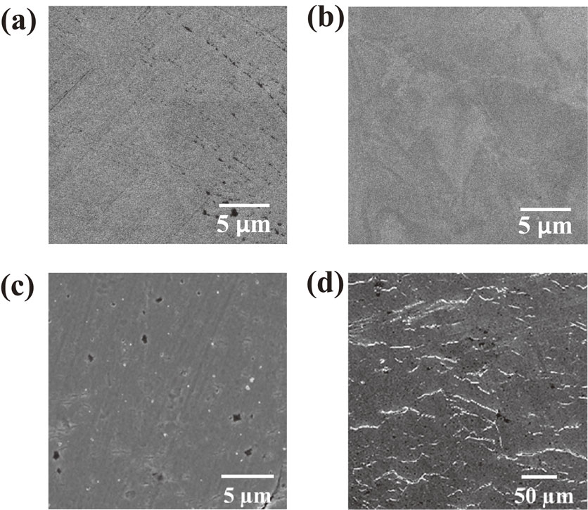
Figure 2(a) presents an AFM image of the surface of Alloy 600 specimen prior to the SSRT. The image reveals an uneven textured surface of the alloy. However, no trenches were formed at the grain boundaries. The back scattered electron (BSE) image and inverse pole figure (IPF) map obtained at an identical location are shown in Figs. 2(b) and 2(c), respectively. The images clearly show that the surface asperity reflects crystallographic orientation, which is consistent with the observation for Alloy 22.30) It was found that crystallographic orientation causes different dissolution rates of the alloy substrate during its mechano-chemical polishing with colloidal silica suspension, which results in this asperity. The asperity indicates that small steps are present at the grain boundary as schematically shown in Fig. 2(d). These small steps cause stress concentration at the grain boundary, leading to crack initiation. Therefore, it can be concluded that the microscopic asperity as shown in Fig. 2(a) facilitates the initiation of IGSCC. From these results, one can deduce that the initiation of IGSCC of Alloy 600 under practical operation might be attributed to the asperity generated as general corrosion by the long-term exposure to a PWR primary environment because of the difference in the dissolution rate based on the crystallographic orientation of grain.

Although this work was conducted to examine the crack initiation on Alloy 600 in a simulated PWR primary environment based on crystallographic information, this type of information could not be obtained from the specimen immediately following the SSRT. As shown in Fig. 3, the specimen surface was covered with an oxide film and many corrosion products. Based on our previous study,23) a relatively thick oxide film was formed on the mill-annealed Alloy 600 during 24-h immersion in a similar PWR primary water environment. In the study, the thickness of the oxide film was estimated to be approximately 24 nm from the intensity attenuation of the Ni metallic peak of the substrate in the hard X-ray photoelectron spectra. The oxide film formed during the SSRT in this study was thicker than the previously reported oxide film on the mill-annealed Alloy 600. This was because the exposure time of Alloy 600 to the simulated PWR primary environment in this work was much longer than that in the previous work. The thick oxide film on the Alloy 600 surface prevented the measurement of electron-backscatter patterns from the underlying substrate. Therefore, the oxide film formed under the high-temperature and high-pressure water environment was removed by Ar+ ion sputtering.

Figure 4(a) shows the SEM image of the Alloy 600 specimen after sputtering. Note that the horizontal direction of the image is parallel to the loading axis of the SSRT. It was evident that the thick oxide film and corrosion products were removed by sputtering, and cracks were clearly observed on the surface after sputtering. More importantly, all cracks were observed at the grain boundaries, indicating that IGSCC occurred on the alloy. Furthermore, many of the cracks initiated approximately perpendicular to the stress axis. Figure 4(b) shows the IPF map of the same location shown in Fig. 4(a). A clear IPF was obtained for the surface of the Alloy 600 specimen after the SSRT. Analysis of crystallographic data with the corresponding SEM image reveals the crystallographic features of IGSCC.

Figure 5 summarizes the probability of crack initiation calculated for the grain boundary with respect to the misorientation angle at the grain boundary. The probability of crack initiation was defined as the ratio of the number of cracked grain boundaries to the total number of grain boundaries for each range of misorientation angle. Furthermore, the probability can be summarized for the two categories of grain boundaries, that is, the random and coincidence site lattice (CSL) boundaries. On the alloy used in this work, three types of CSL boundaries, namely Σ3, Σ9, and Σ27, were recognized, with the calculated misorientation angles of 60°, 38.9°, and 31.6°, respectively. The figure indicates that the probability of crack initiation strongly depends on the type of grain boundary. In other words, cracks initiate more readily at the random grain boundary than at the CSL boundary. In addition, for the random boundary, the probability of crack initiation is higher for the misorientation angles ranging from 30° to 40° as compared to the other ranges of misorientation angles. By contrast, the probability of crack initiation increases with an increasing Σ value for the CSL boundary.

Because the IGSCC cracks initiated and propagated along a grain boundary, gaining information about the grain boundary plane is important to understand the initiation and propagation of cracks. In this study, as illustrated in Fig. 6, the angle between a grain boundary plane and the stress axis was defined as grain-boundary-plane angle, assuming that a grain boundary was flat. However, the direction of the crack could not be determined by an SEM observation, as it was performed only for the upmost surface of the specimen. Therefore, we proposed a three-dimensional characterization of crack initiation, which was realized by repeated polishing and EBSD measurements. First, an EBSD measurement was conducted for the topmost surface after the sputtering as previously mentioned. Then, the surface was gently polished with colloidal silica suspension to remove a layer of approximately 1-µm in thickness from the specimen surface. This resulted in the displacement of the grain boundary based on the angle of the grain boundary plane to the surface. From the displacement of the grain boundary and the thickness of the removed specimen surface, the grain-boundary-plane angle was computed using a trigonometric function. In order to measure the displacement of the grain boundary, IPFs obtained at two different depths were used. Triangular pyramidal indentations were introduced as markers to perform EBSD measurement at the same locations after gentle polishing of the specimen and to estimate the thickness of the specimen removed during the polishing.

IPFs obtained at the same location on the specimen surface before and after gentle polishing are presented in Fig. 7. The grain boundary positions before and after gentle polishing were extracted from the IPFs and are shown to overlap in Fig. 7(c). Figure 7(d) presents a magnified image of the site indicated by the square in Fig. 7(c). The black and red lines in the images indicate the grain boundaries before and after gentle polishing, respectively. As can be seen, some red lines coincide with the black lines, whereas the other red lines deviate from the corresponding black lines. The distance between the lines reflects the displacement of the grain boundary. Using the displacement at each boundary and the removed thickness, we calculated the grain-boundary-plane angle, which is summarized in Fig. 8. Figure 8 presents correlation between the grain-boundary-plane angle and the misorientation angle described above. As presented, more cracks were recognized at the random boundary than at the CSL boundary. Lehockey et al. reported a similar result in which a crack appeared exclusively confined to the random boundary rather than at the CSL boundary.31) Around the misorientation angle of 40° for the random boundary, cracks initiated within a wide range of grain-boundary-plane angle. For other misorientation angle ranges, cracks initiated at the grain-boundary-plane angles of approximately 40°. A similar trend was observed for the CSL boundary as shown in Fig. 8(b), that is, cracks initiated at the grain-boundary-plane angle of approximately 40°, independent of the CSL boundary. Alexandreanu et al. examined the stress corrosion cracking of Alloy 600 in a simulated PWR environment and the deformation behavior of the alloy in Ar environment at 633 K. They compared the distribution of calculated shear stress on grain boundary plane with the distributions of fraction of deformed as well as cracked high-angle boundary against the angle with respect to the tensile direction, that is, the grain boundary plane angle as defined in the present work.32) They found that the calculated shear stress exhibited the similar distribution to the deformed boundary in Ar and the cracked boundary in the PWR environment, that is, they increased with increasing the grain boundary plane angle of 45° and then decreased with the angle, that is, the distribution of cracked boundary is roughly in accordance with Fig. 8. These results indicated that the shear stress may be a driving force not only for the grain boundary deformation but also for IGSCC. Although further analysis is required to discuss in more detail the mechanism of SCC crack initiation in terms of the crystallography of the grain boundary, the results of the present study indicate that the proposed approaches can facilitate the initiation of IGSCC and provide crystallographic information of grain boundaries on the surface as well as inside the alloy.

4. Conclusion
This study reported on the crystallographic characterization of IGSCC cracks initiated on Alloy 600 in a simulated PWR primary environment. Mechano-chemical polishing with colloidal silica suspension facilitated crack initiation. A thick oxide film and many corrosion products were formed on the alloy surface during an SSRT, which prevented EBSD measurement. However, sputtering of the oxide film and corrosion products enabled us to obtain clear IPFs and to analyze the IGSCC cracks crystallographically. The probability of crack initiation was higher at the random than at the CSL boundary, although the probability of crack initiation for the Σ27 boundary was similar to that for the random boundary. Furthermore, grain-boundary-plane angles were calculated from EBSD measurements at different depths, which were achieved by the repeated gentle polishing of the specimen. The grain-boundary-plane angle centered around a specific angle of 40°, independent of the misorientation angle as well as the type of grain boundary (random or CSL). However, at the misorientation angle of approximately 40°, cracks initiated with a wide range of grain-boundary-plane angles.
REFERENCES
- 1) R.A. Page: Corrosion 39 (1983) 409–421.
- 2) R. Bandy and D. Vanrooyen: J. Mater. Energ. Syst. 7 (1985) 237–245.
- 3) J.R. Crum: Corrosion 42 (1986) 368–372.
- 4) S.M. Bruemmer and C.H. Henger: Scr. Metall. 20 (1986) 909–914.
- 5) G. Economy, R.J. Jacko and F.W. Pement: Corrosion 43 (1987) 727–734.
- 6) S.M. Payne and P. McIntyre: Corrosion 44 (1988) 314–319.
- 7) C.H. Shen and P.G. Shewmon: Metall. Trans. A 21 (1990) 1261–1271.
- 8) R.B. Rebak and Z. Szklarska-Smialowska: Corros. Sci. 38 (1996) 971–988.
- 9) T.M. Holden, R.A. Holt and A.P. Clarke: Mater. Sci. Eng. A 246 (1998) 180–198.
- 10) L.E. Thomas and S.M. Bruemmer: Corrosion 56 (2000) 572–587.
- 11) G.A. Young, W.W. Wilkening, D.S. Morton, E. Richey and M. Lewis: Proceedings of the 12th International Conference on Environmental Degradation of Materials in Nuclear Power System – Water Reactor –, (2005) pp. 913–922.
- 12) J.B. Ferguson and H.F. Lopez: Metall. Mater. Trans. A 37 (2006) 2471–2479.
- 13) J. Panter, B. Viguir, J.-M. Choué, M. Foucault, P. Combrade and E. Andrieu: J. Nucl. Mater. 348 (2006) 213–221.
- 14) J. Hou, Q.J. Peng, T. Shoji, J.Q. Wang, E.-H. Han and W. Ke: Corros. Sci. 53 (2011) 2956–2962.
- 15) Z. Lu, T. Shoji, S. Yamazaki and K. Ogawa: Corros. Sci. 58 (2012) 211–228.
- 16) K. Arioka, T. Yamada, T. Miyamoto and M. Aoki: Corrosion 70 (2014) 695–707.
- 17) A. Telang, A.S. Gill, D. Tammana, X. Wen, M. Kumar, S. Teysseyre, S.R. Mannava, D. Qian and V.K. Vasudevan: Mater. Sci. Eng. A 648 (2015) 280–288.
- 18) D.K. Schreiber, M.J. Olszta, D.W. Saxey, K. Kruska, K.L. Moore, S. Lozano-Perez and S.M. Bruemmer: Microsc. Microanal. 19 (2013) 676–687.
- 19) M. Kamaya, A.J. Wilkinson and J.M. Titchmarsh: Acta Mater. 54 (2006) 539–548.
- 20) L.N. Brewer, M.A. Othon, L.M. Young and T.M. Angeliu: Microsc. Microanal. 12 (2006) 85–91.
- 21) A. Sáez-Maderuelo, L. Castro and G. de Diego: J. Nucl. Mater. 416 (2011) 75–79.
- 22) Q. Peng, J. Hou, K. Sakaguchi, Y. Takeda and T. Shoji: Electrochim. Acta 56 (2011) 8375–8386.
- 23) S. Fujimoto, W.-S. Kim, M. Sato, J.-Y. Son, M. Machida, K.-T. Jung and H. Tsuchiya: J. Solid State Electrochem. 19 (2015) 3521–3531.
- 24) K.-T. Jung, T. Ogawa, Y. Morita and S. Fujimoto: Proceedings of 17th International Conference on Environmental Degradation of Materials in Nuclear Power Systems-Water Reactors, (2015).
- 25) J.E. Spowart: Scr. Mater. 55 (2006) 5–10.
- 26) A.C. Lewis, J.F. Bingert, D.J. Rowenhorst, A. Gupta, A.B. Geltmacher and G. Spanos: Mater. Sci. Eng. A 418 (2006) 11–18.
- 27) S. Zaefferer, S.I. Wright and D. Raabe: Metall. Mater. Trans. A 39 (2008) 374–389.
- 28) N. Totsuka, E. Lunarska, G. Cragnolino and Z. Szklarska-Smialowska: Corrosion 43 (1987) 505–514.
- 29) S. Fujimoto, H. Masaki and T. Saito: Proceedings of Workshop on Detection, Avoidance, Mechanisms, Modeling, and Prediction of SCC Initiation in Water-Cooled Nuclear Reactor Plants, (2008).
- 30) J.J. Gray, B.S. El Dasher and C.A. Orme: Surf. Sci. 600 (2006) 2488–2494.
- 31) E.M. Lehockey, G. Palumbo and P. Lin: Metall. Mater. Trans. A 29 (1998) 3069–3079.
- 32) B. Alexandreanu and G.S. Was: Corrosion 59 (2003) 705–720.

