Microstructure of Materials
Cu-Containing High Entropy Alloys for Nuclear Fusion Application
2020 Volume 61 Issue 7 Pages 1247-1251

Details
2020 Volume 61 Issue 7 Pages 1247-1251
Face-centered cubic Co-free Cu-containing solid solution concentrated alloys, Cu, CuNi, CuNiFe, Cu0.3NiFeCr, Al0.4CuFeCrNi2 were prepared, and their microstructure, hardness, and tensile strengths were investigated in order to develop a new high entropy alloy with a high irradiation resistance, which is applicable for nuclear reactor components. All the as-cast alloys were identified as single-phase FCC alloys by X-ray diffraction analysis. While, the SEM observation indicated a new Cr-rich phase with Cu-rich phase in the annealed Cu0.3NiFeCr alloy, which is probably due to low solubility of Cr and Cu in the alloy. After annealing at 1076°C for 120 hours, Cu0.3NiFeCr alloy became a single-phase FCC. Mechanical property examinations indicated the highest Vickers hardness, the highest Tensile strength and the smallest elongation in the Al0.4CuFeCrNi2. The results indicate that the Al0.4CuFeCrNi2 alloy would have the potential to be a Co-free high-entropy alloy applicable to nuclear reactor components. In order to improve the elongation of Al0.4CuFeCrNi2, the detailed analysis of fracture surface and the optimization of annealing condition would be needed.
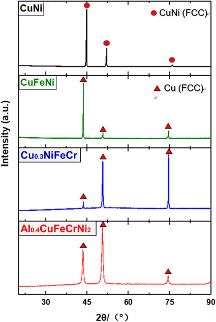
Fig. 1 XRD patterns for the Co-free Cu-containing solid solution concentrated alloys.
In recent years, the high entropy alloys (HEAs) has been attracting attention as a unique material. According to the composition-based definition, HEAs contain five or more elements in equiatomic or near equiatomic ratios with element concentrations between 5% and 35%.1) Some HEAs have single-phase crystal structures due to the increase in the configurational entropy.2–9) The entropy-based definition characterizes the HEA by the maximum entropy possible and implies that such a state is achieved at high temperatures or in the liquid state.10) During the last decade, many researches have been carried out in understanding the criteria governing the formation of a simple solid solution with multiple components. Takeuchi et al.11) suggested that the formation of simple solid solution phases was promoted if the enthalpy of mixing (ΔHmix) was in the range of 7–22 kJ/mol and an atomic size difference factor (δ) was less than 8.5%. Furthermore, it has been reported that several HEAs have good mechanical properties from cryogenic temperatures to high temperatures.12–16) Based on those researches, some HEAs can be suggested as a structural material and as coatings.17–19) George et al.20) have summarized the research on HEAs.
In the current water-cooled nuclear fission reactors, austenitic stainless steels are widely used as structural materials. High-performance steels are considered to be essential for numerous proposed nuclear energy systems that require radiation doses up to 100–200 displacements per atoms (dpa). Currently, there is no high radiation resistance austenitic stainless steels available for extended operations at elevated temperatures for the next generation of nuclear energy systems. One of the candidate materials for next-generation nuclear reactor components could be FCC type HEAs. Some recent papers have reported the initial examination of the fundamental irradiation behavior in HEAs,21,22) thereby giving insight into the potential of those materials for nuclear applications.
Considering a candidate HEA for nuclear application, the radioactive elements should be eliminated from the material design based on radiation shielding requirements during handling and the maintenance of components. It is reported that Co-based alloys exhibit the expected mechanical behavior and constitute a good solution for the use in next-generation nuclear energy systems.1,21,22) However, Co would be highly activated by neutron irradiation.23,24) In this study, therefore, face-centered cubic Co-free solid solution concentrated alloys were prepared in order to investigate their microstructure, mechanical properties as a basic study of the development of HEA applicable to the nuclear environment.
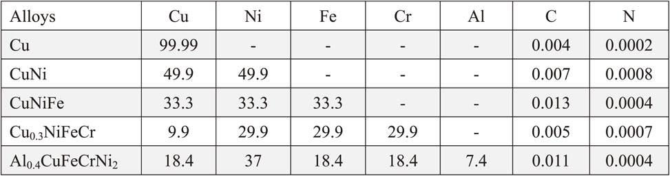
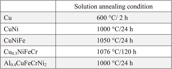
In this study, pure copper, nickel, iron, chromium, and aluminum (>99.9% purity) were used as raw material for fabrication of the face-centered cubic Co-free Cu-containing single-phase concentrated solid-solution alloys. CuNi and CuNiFe alloys were prepared by arc-melting with the buttons flipped and melted more than ten times to ensure well-mixed before drop-casting into a copper mold. Based on previous research,25) non-equimolar composition Cu0.3NiFeCr and Al0.4CuFeCrNi2 were chosen for getting single-phase alloys. Cu0.3NiFeCr and Al0.4CuFeCrNi2 alloys were prepared by induction furnace in a high purity argon atmosphere. The chemical compositions of the five alloys which were identified by ED-XRF (Energy Dispersive X-Ray Fluorescence) spectrometer are listed in Table 1. Based on phase diagrams and previous research,25) all ingots were solution-annealed in order to obtain homogeneity. The solution annealing conditions of the five alloys are listed in Table 2. The microstructure of the alloys was observed by scanning electron microscope (SEM, JSM-6510LA) equipped with an energy dispersive spectrometer (EDS) with an accelerating voltage of 15 kV. The crystal structure of the as-cast and annealed specimens was identified by X-ray diffraction (SmartLab XRD) at a speed of 6°/min with Cu Kα radiation. The hardness of the samples was measured using Vickers indenter (Struers) at room temperature under a load of 1 kg with a dwell time of 15 s. Tensile test was also carried out for SSJ-type small tensile samples (the gauge section dimension of 0.25 × 1 × 5 mm) at a strain rate of 10−3 s−1 with an INSTRON 5564 tensile tester.
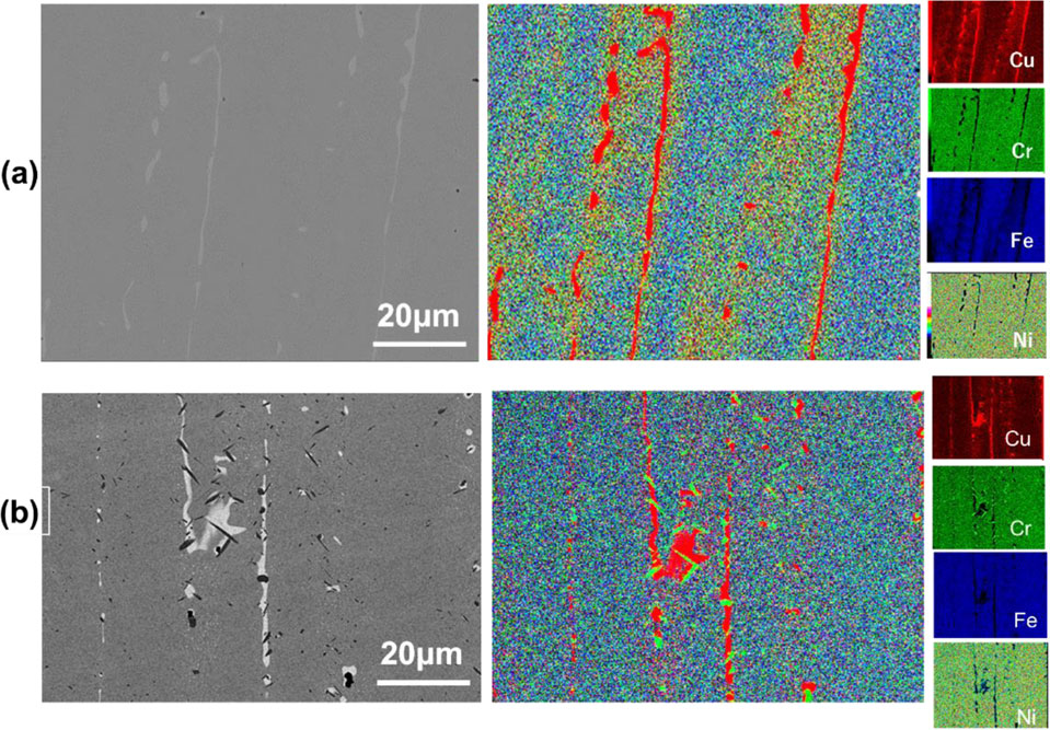
The phases in the Cu-containing alloys were firstly determined by using XRD. Figure 1 shows the diffraction peaks of CuNi, CuFeNi, Cu0.3NiFeCr, and Al0.4CuFeCrNi2. The diffraction peaks of both as-cast and solution-annealed CuNi matched with a single-phase FCC CuNi. While, the diffraction peaks of both as-cast and solution-annealed CuFeNi, Cu0.3NiFeCr and Al0.4CuFeCrNi2 matched with a single-phase FCC Cu. Therefore, all the prepared Co-free Cu-containing alloys would have face-centered cubic structures. The BEC image and the EDS mapping image of CuNi, CuFeNi, and Al0.4CuFeCrNi2 showed no contrast and homogeneous, respectively. Figure 2 and Fig. 3 shows the typical SEM-BEC (Backscattered Electron Composition) images and the EDS mapping of solution-annealed Al0.4CuFeCrNi2.

XRD patterns for the Co-free Cu-containing solid solution concentrated alloys.
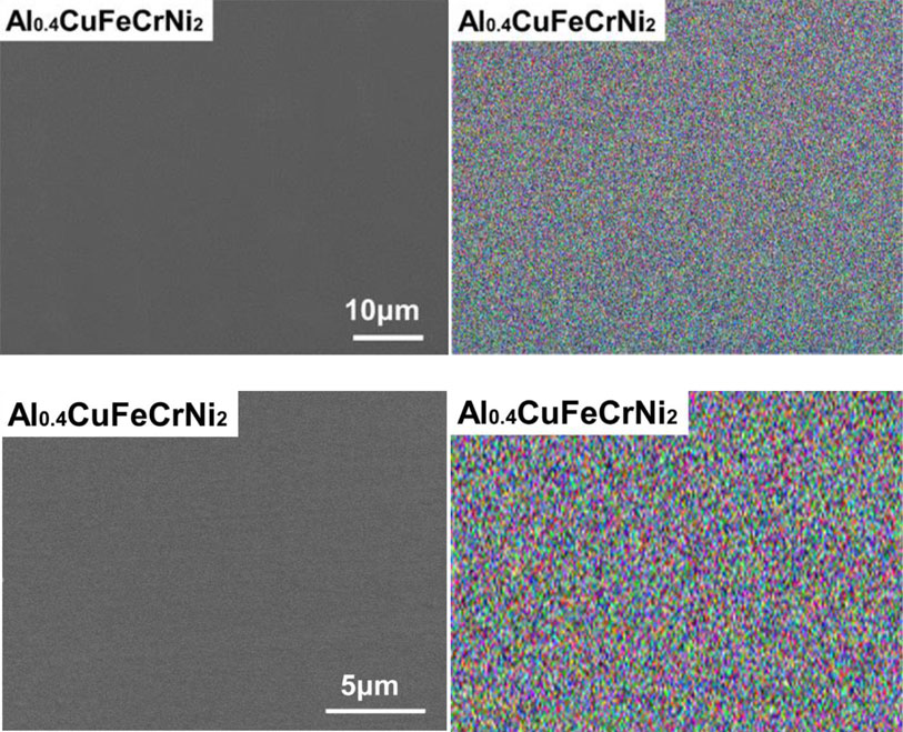
Typical SEM-BEC images and EDS mapping images of solution annealed Al0.4CuFeCrNi2.
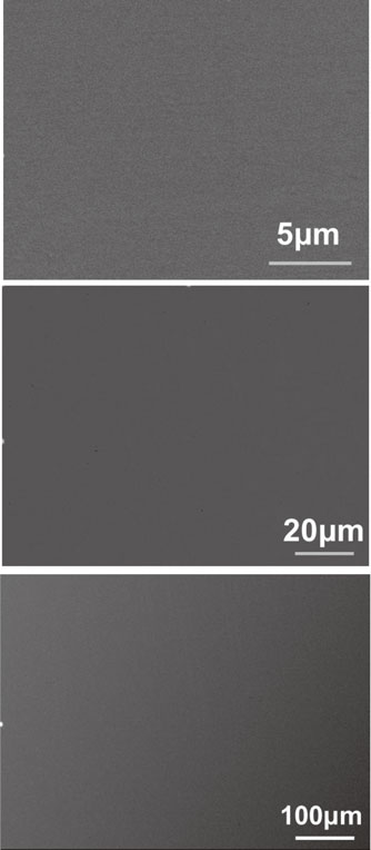
Typical SEM-BEC images of Al0.4CuFeCrNi2 at different magnifications (X5000, X1000, and X200).
On the other hand, the SEM-BEC image of as-cast Cu0.3NiFeCr alloy showed inhomogeneously. Figure 4 shows the SEM-BEC images and the EDS mapping images of as-cast and 1000°C/24 h annealed Cu0.3NiFeCr alloy. The as-cast Cu0.3NiFeCr alloy included the Cu-rich phase shown in light gray contrast in the SEM-BEC image and red color in the EDS mapping (Fig. 4(a)). As mentioned above, the diffraction peaks of Cu0.3NiFeCr alloy matched with a single-phase FCC Cu, meaning that the matrix and Cu-rich phase were not distinguished by XRD. Figure 4(b) shows the microstructure of Cu0.3NiFeCr alloy annealed at 1000°C for 24 hours. During annealing, a new Cr-rich phase (dark contrast) formed on the Cu-rich (light gray contrast) phase as shown in the EDS mapping. This phenomenon was caused probably due to the low solubility of copper and chromium. Based on the Cu–Cr phase diagram, the eutectic temperature (1076°C) was chosen as the annealing temperature of Cu0.3NiFeCr. Figure 5(a)–(d) shows the SEM-BEC images of Cu0.3NiFeCr annealed at 1076°C for 24, 48, 72 and 120 hours. In the as-cast Cu0.3NiFeCr, the Cu-rich phase existed in the matrix as a dendritic structure (Fig. 5(a)). The dendritic Cu-rich phase seemed to be decomposed after annealing at 1076°C for 24 hours (Fig. 5(b)). Furthermore, the Cu-rich phase enriched at the grain boundaries after annealing for 48 hours (Fig. 5(c)) and disappeared after 120 hours (Fig. 5(d)). Finally, a single-phase FCC structure of Cu0.3NiFeCr alloy was obtained after annealing at 1076°C for 120 hours.
Typical SEM BEC images and the EDS mapping of (a) as-cast and (b) 1000°C/24 h annealed Cu0.3NiFeCr alloy.
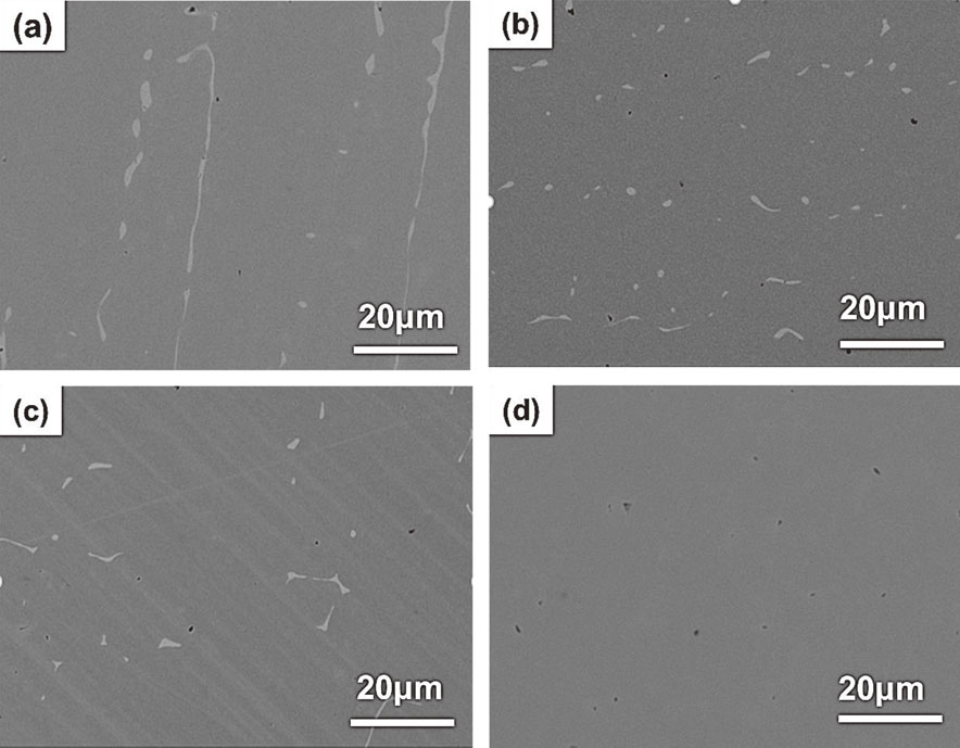
Typical SEM-BEC images of Cu0.3NiFeCr annealed at 1076°C for (a) 24, (b) 48, (c) 72 and (d) 120 hours.
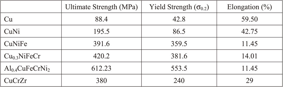
Figure 6 shows the Vickers hardness of the as-cast and the solution-annealed alloys. The Vickers hardness of annealed alloys was similar to that of as-cast alloys. While the hardness seemed to increase with increasing the number of elements. This would be due to the general solid solution hardening effect. It should be noted that the hardness of Al0.4CuFeCrNi2 exhibited much higher (204 HV) compared to that of CuCrZr alloy (68–93 HV), which would be used for the high heat flux components of the International Thermonuclear Experimental Reactor (ITER).26) Figure 7 shows the stress-strain curves of all the solution-annealed alloys and CuCrZr alloy as a comparison. The values of ultimate strength, yield strength (σ0.2) and elongation of all the alloys at room temperature are listed in Table 3. The results showed the increase in strength with increasing the number of elements probably due to solid solution strengthening effect. The Al0.4CuFeCrNi2 exhibited the highest strength and the smallest elongation. Comparing with the tensile property of CuCrZr alloy, the Al0.4CuFeCrNi2 showed higher strength and lower elongation. Besides, the elongation of Al0.4CuFeCrNi2 was almost similar to that of CuNiFe and Cu0.3NiFeCr alloy, suggesting that the Al0.4CuFeCrNi2 would have a higher ductility than CuNiFe and Cu0.3NiFeCr alloy. In order to improve the ultimate elongation of Al0.4CuFeCrNi2, the detailed analysis of fracture surface and the optimization of annealing condition would be needed. It has been known that the catastrophic fracture mechanism occurs in three stages: 1) nucleation, 2) growth and 3) coalescence of voids.27) Generally, under the same fracture conditions, the larger the dimple size, the lower the plasticity of the material. And, the solution treatment and aging affect the dimple size, thereby changing the type of failure.28) Therefore, analysis of the effect of different solution treatment temperature and aging time on the plasticity of samples would be needed.
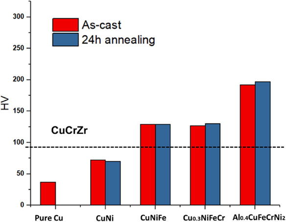
Vickers hardness of all the alloys of as-cast and solution-annealed for 24 hours.
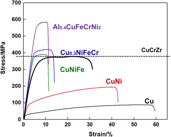
Stress-strain curves of all the solution-annealed alloys and CuCrZr as a comparison.
The Co-free Cu-containing solid solution concentrated alloys, Cu, CuNi, CuNiFe, Cu0.3NiFeCr, Al0.4CuFeCrNi2 were investigated in order to find a proper high entropy alloy for nuclear reactor application. Solution-annealed CuNi, CuFeNi, and Al0.4CuFeCrNi2 showed single-phase FCC structures with the homogeneous atomic distribution. Solution-annealed Cu0.3NiFeCr alloy included the dendritic Cu-rich phase in matrix, however, a single-phase FCC structure of Cu0.3NiFeCr alloy was finally obtained after annealing at 1076°C for 120 hours due to the decomposition of the Cu-rich phase. Mechanical property examinations revealed that the order of the Vickers hardness and the Tensile strength was Cu < CuNi < CuNiFe < Cu0.3NiFeCr < Al0.4CuFeCrNi2. The results indicate that the Al0.4CuFeCrNi2 alloy would have the potential to be a Co-free high-entropy alloy applicable to nuclear reactor components. Further experiments on the irradiation resistance properties, such as ion and electron beam irradiation, of these alloys would be needed.
This work was supported by JSPS Grant-in-Aid for Scientific Research on Innovative Areas Grant Number JP19H05161 and partially supported by the China Scholarship Council.