Abstract
It is well known that severe plastic deformation (SPD) produces ultrafine-grained structures in bulk metallic materials. The SPD process becomes more versatile when it is performed under high pressure as high-pressure torsion (HPT) and high-pressure sliding (HPS). Not only the grain size is more refined but also the process is applicable to hard-to-deform materials such as intermetallics, semiconductors and ceramics, leading to enhancement of functional properties as well as structural properties. The major drawback is that the sample size is small so that the applicability is limited to a laboratory scale and it is an important subject to increase the sample dimensions. This paper presents an overview describing efforts devoted thus far to deal with this upscaling issue.
1. Introduction
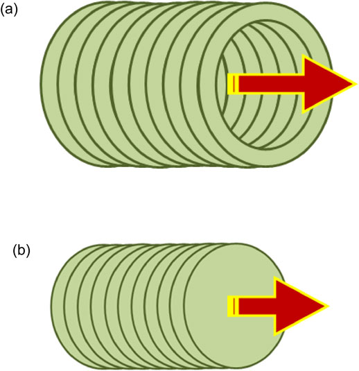
Severe plastic deformation (SPD) is a useful process for microstructural refinement to the submicrometer and/or nanometer range in bulk metallic materials.1,2) When the SPD process is performed under high pressure through high-pressure torsion (HPT)3) and high-pressure sliding (HPS)4) as illustrated in Fig. 1(a) and (b), respectively, its applicability is further extended in comparison with other SPD processes such as equal-channel angular pressing (ECAP)5) and accumulative roll bonding (ARB).6) This is because the sample is better constrained due to the application of high pressure. The SPD process under high pressure thus permits not only (1) grain refinement but also (2) fragmentation of second phase particles to a fine dispersion of nanosized particles,7) (3) dissolution of the second phase particles in the matrix,8–10) (4) consolidation of powders, chips and layers to attain alloying through solid-state reaction,11–34) (5) fabrication of metal-matrix composites without sintering process,35–45) (6) nanostructure control through subsequent combination with annealing or aging,46–57) (7) pressure- and/or strain-induced phase transformation.34,58–66) With such peculiar features, it is possible to enhance mechanical properties such as strength and ductility67–71) and functionality of materials such as hydrogen storage capability,72–76) electrical conductivity,77–83) superconductivity,84–88) photocatalytic activity,89–91) photoluminescence,63,92) thermoelectrical property,93,94) dielectrical properties,95) magnetic properties96,97) and biocompatibility98) including materials with high radiation resistance99) and corrosion resistance.100) Despite the versatility of the HPT and HPS processes, the sample size is rather limited to a laboratory scale. It is thus an important subject to scale up the sample dimensions and/or to make the processes continuous so that a large quantity with high performance retained can be produced for practical applications.

In July and August, 2019, a special issue was edited in Materials Transactions under the title of “Severe Plastic Deformation for Nanomaterials with Advanced Functionality”.101) A total of 41 articles was published, including Review, Overview and Regular articles, covering recent studies on structural and functional properties, historical studies of SPD,102) modeling and simulation,64,103) materials synthesis,32–34) roles of lattice defects,104–108) grain refinement and microstructural evolution,109–112) applications to polymers113) and metallic grasses,114) surface and microstructural modifications by SPD.115–119) However, no article was concerned with the subject of scaling up using SPD process under high pressure except one regular article where the capacity of HPT process was increased to 500 ton and applied to Mg alloys for enhancement of mechanical properties.120) Therefore, this paper intends to present an overview describing efforts devoted thus far to deal with such difficulties.
2. High-Pressure Torsion (HPT)
2.1 Principle and advantage of HPT
Bridgman is the first to introduce the process of HPT.3) Many materials including metals, alloys, polymers, ceramics, rocks, and even woods were applied with this HPT process as reviewed recently.121) In the HPT processing, a disk is placed in the central shallow hole on a lower anvil which is then raised to contact the upper anvil as illustrated in Fig. 1(a). While applying a high pressure with normally more than 1 GPa, the upper and lower anvils are rotated with respect to each other. An advantage of the HPT process is that the grain size is reduced more finely than other SPD processes. It was reported that the grain size was reduced to ∼90 nm by the HPT process122) while it was ∼270 nm by ECAP on an Al–3%Mg alloy.123) Further advantage is that the HPT process is applicable to hard-to-deform materials and/or low ductility materials:124–126) for example, processing of Mg alloys by HPT is achieved at room temperature,120,127–129) but raising temperature at least as 100°C or higher is required for the ECAP processing.130–137)
2.2 Limitation of HPT
Despite the advantage of HPT processing, a major drawback is that the sample size is limited to disks with dimensions typically as 10 mm in diameter. Recently, the machine capacity was scaled up from 50 to 500 ton,120) and this increase then allowed to enlarge the sample dimensions from 10 to 30 mm in diameter under the same applied pressure of 6 GPa.120) The sample size can be increased to 70 mm diameter for the applied pressure of 1 GPa which may be sufficient for processing soft materials as pure aluminum and less-hardened aluminum alloys without causing slippage between the sample and the anvil.138) If the sample is harder, the applied pressure should be increased to avoid the slippage as inspected by Edalati et al.138) Recently, the machine capacity of 1000 ton is available in the Leoben’s group in Austria.139) This machine was used to process a cupper disk with 60 mm diameter and 12 mm thickness. With this machine, the dimeter could be increased to 100 mm for the applied pressure of 1 GPa and be 45 mm for 6 GPa.
2.3 Application to rings
There is another drawback inherent in the HPT processing using disk samples. That is inhomogeneous development of microstructure and of related mechanical properties. Because the strain (ε) is introduced through the equation ε = rθ/t, where r is the distance from the disk center, θ is the rotation angle and t is the thickness of the sample.3) Thus, less strain is generated around the center region (theoretically zero at r = 0). This inhomogeneity of strain distribution and microstructural development may be useful when the effect of strain is examined. However, the microstructure and mechanical properties should be homogeneous throughout the sample when practical application is the prime object. Such a microstructural inhomogeneity including the drawback due to the limitation of sample size may be solved by using ring sample instead of disk sample since the central part is removed. In fact, the idea of using ring sample was implied by Bridgman3) with a statement that the use of a hollow tube should be free from the inhomogeneity. Erbel realized later the process using the ring form,140) and the processing with ring was developed further by Saunders and Nutting to attain fine microstructures in Cu despite the pressures rather low as 200–500 MPa.141) Harai et al. demonstrated that the facilities for the ring sample is simplified by modifying anvils used for disk samples in the conventional HPT process as illustrated in Fig. 2.142) The application using ring samples were made with 20 mm in outer diameter with the ring width of 3 mm in pure Al,142) and extended to the sample sizes with outer diameters of 30 mm on Cu143,144) and Fe145) and of 40 mm on an Al–3%Mg–0.2%Sc alloy.146) Finally, as shown in Fig. 3 in comparison with 10 mm and 20 mm diameter disks, it was successful to process ring sample with a diameter of 100 mm in pure Al.147)

It should be noted that increasing the sample diameter is more favorable to establish a homogeneous microstructure. Figure 4(a) shows that the hardness saturates as the distance from the rotation center increases, which is more clearly demonstrated when the hardness is plotted as a function of equivalent strain as in Fig. 4(b).146) This indicates that the increase in the diameter provides a chance that a homogeneous microstructure is more likely to develop.
3. High-Pressure Sliding (HPS)
3.1 Principle and advantage of HPS
While Bridgman rotated the anvils with respect to each other to produce shear strain in a disk sample,3) anvils may be moved in a reciprocal way as illustrated in Fig. 1(b). In practice, this was realized by introduction of the HPS process.4) The HPS process was initially developed with a rectangular sheet4,148–150) and later it was shown that it is also applicable to rods.151–153) The HPS process has such an advantage that it is applicable to hard-to-deform materials as the HPT process. The application was then made not only to common metals and alloys such as pure Al and Al–Mg alloys4,148,154) but also to high-strength age-hardenable Al alloys,149,150,154,155) less ductile Mg alloys,151,153,154) a two-phase Ti alloy,154) a Ni-based superalloy (Inconel 718)154) and a creep-resistant P62 steel.156,157) It is noted that a modified version of the HPS process was recently presented by Toth et al.158) using pure Cu, where a significant fraction of compression strain was introduced together with shear strain during the HPS processing.
As in the HPT process, the increase in machine capacity increases the dimensions of workpiece. The initial dimensions with the rectangular sheets was of 3 (or 5) × 100 × 1 mm for the machine capacity of 50 ton4) but the size was increased to 30 (or 50) × 100 × 1 mm as illustrated in Fig. 5 as the machine capacity increased to 500 ton.154) The size of the workpiece was further increased by the combination with feeding process, which was called the incremental feeding HPS (IF-HPS).159,160) Further summary will be given later.
3.2 Application to rods
SPD Processing of rods is usually achieved through ECAP, but nevertheless, Masuda et al. showed that the HPS process is applicable to rod samples.151–153) In the HPS process, a rod sample is rotated along the longitudinal axis after each sliding pass as illustrated in Fig. 6 where (a) is for 90° rotation and (b) for 60° rotation so that homogeneity of microstructure can be achieved throughout the cross section of the rod. Examination revealed that at least a 60° rotation was required for a homogeneous development of the microstructure in a 10 mm diameter rod. This process was called the multi-pass HPS (MP-HPS) and was applied not only to pure Al and a superplastic Al–3%Mg–0.2%Sc alloy151,152) but also age-hardenable high-strength Al alloys such as A2024 and A7075.151) The MP-HPS process was also applied to a less ductile Mg alloy such as AZ61151,153) and a Ni-based superalloy (Inconel718) at room temperature under a pressure of 1–2 GPa.155) A hardness variation throughout the cross section of the Ni-based superalloy is shown in Fig. 7, where MP-HPS-R represents the multi-pass HPS with rotation. It should be noted that the shape of the cross section is hexagonal, and this is due to the cross sectional shape of the groove in the upper and lower anvils. Because of the hexagonal shape, it is easy to rotate the rod sample by 60° around the longitudinal axis. To increase the constrained conditions, the grooves on the upper and lower anvils were closed at both sides like a pocket as illustrated in Fig. 8. For this case, a reciprocal forward and backward motion was required to eliminate the gaps formed after forward motion (i.e., to maintain the rod without the gaps) as in Fig. 9. Observations by transmission electron microscopy (TEM) showed that the grain sizes were significantly reduced, and thus superplasticity was well attained in all the alloys.151–153,155) Tang et al. showed that the microstructural homogeneity may also be achieved by shifting upward and downward from the mid-height on the cross-sectional plane155) as illustrated in Fig. 10. This process was then designated as MP-HPS-S and distinguished from MP-HPS-R, where S stands for sift and R for rotation. Most recently, it was reported that the sample diameter can be increased to 16 mm in diameter in the Al–3%Mg–0.2%Sc alloy.161)

For processing of pipe samples, two approaches are suggested as illustrated in Fig. 11.162) Placing a mandrel in the center of the pipe, shear strain is introduced in the angular direction through rotation of the mandrel with respect to the anvils (lower left) and in the longitudinal direction through reciprocal movement of the mandrel with respect to the anvils (lower right). The former is the modification based on the HPT process for rings with the rotation involved, whereas the latter is the one based on the HPS process for rods with the reciprocation involved. In fact, two groups of Toth et al.163–165) and Wang et al.166) utilized the rotation type (called high pressure tube twisting (HPTT) for the former and tube high pressure shearing (t-HPS) for the latter) and showed that it was feasible to introduce intense shear strain throughout the thickness of the pipe. Tang et al. processed the pipe using the reciprocation type to introduce intense shear strain along the longitudinal direction of the pipe.162)

As schematically illustrated in Fig. 12, a pipe sample is placed between the grooves with half circles in cross sections made on the upper and lower anvils. A mandrel is inserted in the pipe to keep the inner hole unchanged when a pressure is applied. Two approaches were proposed to introduce intense shear strain in the pipe:162) one is to slide the lower anvil with respect to the upper anvil under high pressure while the mandrel was kept in the pipe as lower left of Fig. 12 (called anvil sliding), and the other is to slide the mandrel with respect to the upper and lower anvils under high pressure where the mandrel is used as a plunger as lower right of Fig. 12 (called mandrel sliding). Figure 13(a) and (b) shows hardness variations after application of both the anvils sliding and mandrel sliding, respectively,162) to an Al–3%Mg–0.2%Sc alloy which is known to exhibit superplastic elongations when intense strain is introduced by SPD processes.154,155,167–169) It appears that the hardness variation is not homogeneous after one sliding pass. More strain is introduced around the horizontal sides of the cross section for the anvil sliding and around the vertical sides for the mandrel sliding. Analysis by finite element method (FEM) confirmed this inhomogeneity in consistence with the hardness variations.162) Thus, to achieve a homogeneous development of microstructure throughout the cross section, the pipe sample is rotated, as the rod sample in Fig. 6, by 60° or 90° around the longitudinal axis before the successive processing for both the anvil sliding and mandrel sliding. Microstructural observation by TEM revealed that the grain refinement was achieved throughout the pipe samples, and tensile testing at higher temperature showed that superplasticity was well attained.162)

4. Sample Thickness in HPT and HPS Processes
The HPT process generally uses sample thicknesses of ∼1 mm and this is also the case for the HPS process. Sakai et al.170,171) used cylindrical thick samples for the HPT processing and it was reported that the strain was preferentially introduced around the center of the cylinder height170,171) and the corresponding area led to the advent of superplasticity because of the grain refinement.172) A similar trend was observed when the HPS process was applied to rods.151–153,155) Thus, to achieve a homogeneous development of microstructure, Hohenwarter173) moved the cylindrical sample along the longitudinal direction after processing by HPT and Masuda et al.151–153) rotated the rod sample around the longitudinal axis after processing by HPS as shown in Fig. 6. Iwaoka et al. examined how the strained region changes with the number of revolution in the HPT processing for ring samples174–176) and with the sliding distance in the HPS processing175) in terms of optical microscopy, transmission electron microscopy and hardness measurement as illustrated in Fig. 14. The width of the strained region increased with increasing the number of the revolution as shown in Fig. 15 and the sliding distance as shown in Fig. 16. It appears that the strained region covers almost the entire area of the cross section when the thickness is 2 mm after revolution of N = 10 (ε = 245) and after sliding of X = 30 mm (ε = 8.0). However, when the thickness is 4 mm, the strained region saturates but does not reach the total thickness of the sample as plotted in Fig. 17. By changing the ratio of the thickness to the disk diameter, Hohenwarter et al.177) examined the effect of the thickness on the microstructural homogeneity and reported that there was a thickness limitation for achieving homogeneous microstructure throughout the thickness direction. It appears that the thickness limitation depends on the diameter of the disk so that, as the disk diameter is larger, the critical thickness may be increased.177) More systematic studies are required not only from the point of view of the sample geometry but also of the metallic types with different work hardening coefficients.

5. Scaling Up of Sample Dimensions
5.1 Using continuous process
Continuous processing is also an effective way to enhance the quantity even though the machine capacity is small. Here, the “continuous” for SPD is defined such that straining through the SPD process is achieved without intermittence as the conventional rolling process. An extensive review was given by Faraji and Torabzadeh for the continuous SPD processes.178) This definition applies to the SPD processes including the combination of conforming and ECAP processing,179–181) although it is difficult to apply high pressure during the SPD processing. Edalati et al. proposed a continuous process of HPT (CHPT) for both strip and wire182–185) and with such methods, it is possible to apply high pressure. Figure 18 schematically illustrates the facility for wire184) and the same principle is applied to the form of strip.182,183) The facility for the continuous HPT consists of a lower anvil having a circular groove with the surface roughened and an upper anvil having a half circular groove with the surface smooth. Both grooves have circular cross sections where the wire fits well with a slightly bigger diameter. Either of the anvils may be fixed so that wire may be fed during the processing. Since the surface roughness of the groove on the upper anvil is intentionally reduced with respect to the surface roughness of the groove on the lower anvil, a continuous flow of the material occurs in the rotating direction because of the difference in slippage. The wire is also bent slightly upward and pulled out in tension during the process to maintain continuous flow of materials. Most recently, Masuda et al. further developed the CHPT process for multi-wires.186) As shown in Fig. 19 for the operation of two wires, guiding holes for the wires were made on the upper anvil at both entrance and exit sides of the grooves so that no interference of the wires occurred. The grooves were also made symmetrically with respect to the rotation center and thus the CHPT process was able to be operated in a stable geometry without causing damages or breaking of the anvils. It was suggested that multi wires can be processed simultaneously when the anvil diameter is expanded with the groove length kept the same (r1θ1 = r2θ2 = r3θ3) as depicted in Fig. 20.186)

Although the increase in the machine capacity is a direct solution for scaling up the sample dimensions, the HPS machine with the capacity of 500 ton may be still insufficient for hard materials as the Ni-based superalloy because a higher pressure is required to avoid slippage between the sample and the anvil. The solution proposed to overcome this difficulty is the introduction of a technique called incremental feeding HPS (IF-HPS) as illustrated in Fig. 21.159,160) Here, the sliding for strain introduction is followed by feeding of the sheet so that it is possible to increase the processed area as illustrated in Fig. 22. An important requisite to carry out this IF-HPS process is that the grooves to constraint the sample is eliminated (i.e. with non-constrained conditions) but flat anvils are used to permit the sample feeding possible without making a large difference in thickness. This technique was applied to a Ni-based superalloy (Inconel 718) and it was possible to enlarge the SPD-processed area as large as 100 × 100 mm as shown in Fig. 23. This corresponds to the machine capacity ten times as large as the area covered by a single pass. A circular disk extracted from the sheet was then subjected to cup forming at 1073 K in air, and it was successful as shown in Fig. 23 for the side and top views while this forming was not possible when the sheet was not processed by IF-HPS.

Taking advantages of the ring processing, Shigeno et al. showed that it was possible to increase the diameter of the HPT-processed area without increasing the machine capacity.187) As illustrated in Fig. 24, a pair of upper and lower anvils are used with the combination of disks and rings with different diameters so that the total diameter of the processed area is enlarged. This combined process was called the incremental feeding HPT (IF-HPT) and was developed in conjunction with the incremental feeding HPS (IF-HPS) described above. Figure 25 is a sample configuration after processing with three pairs of upper and lower anvils with dimensions of 35 mm diameter for disk, of 35–50 mm inner- and outer-diameter and 50–60 mm inner- and outer-diameter for rings. It is important to note that neither anvils have holes nor grooves to constrain the sample but they are used with flat conditions as for the IF-HPS process. It was confirmed that microstructure as well as the mechanical properties are homogeneous across the diameter. Figure 26 shows (a) the positions where the tensile specimens were extracted, (b) the appearance of tensile specimens after tensile testing at 1073 K with an initial strain rate of 2.0 × 10⁻² s−1 including the specimen before testing and (c) stress-elongation curves after testing at the corresponding conditions. The total elongation exceeds more than 600% except the specimens taken from the outer part. The reduced elongation at the outer part is due to some slippage between the anvils and the sample so that less strain is introduced because the torques are higher at the outer parts of the SPD area. Nevertheless, grain refinement occurs to produce the total elongation of ∼300%.

It should be noted that the use of this IF-HPT process is equivalent to the machine capacity of 1,500 ton which is 3 times higher than the real capacity (500 ton) of the HPT machine used for the process with a single pair of anvils. Shigeno et al. further suggested that the SPD area is enlarged by sequential movement of a sheet with respect to the upper and lower anvils as illustrated by the arrows in Fig. 27,187) where the ring-type anvils are used in Fig. 27(a) and the disk-type in Fig. 27(b). It should be noted that the use of the ring-type anvils can cover a larger area than that of the disk type when the applied pressure is the same. A similar idea was also suggested by Hohenwarter and Pippan.188)
6. Summary
The processes of severe plastic deformation (SPD) under high pressure such as high-pressure torsion (HPT) and high-pressure sliding (HPS) are promising for microstructural refinement and materials synthesis as it is applicable to hard and less ductile materials even including intermetallics, ceramics and semiconductors. As a consequence, it has been demonstrated that the functional properties as well as the structural properties are improved, and occasionally materials with new functionalities are created. However, the sample size is small so that the practical application has been limited. This is an important subject to overcome as the practical application of the SPD processes is strongly desired. This overview summarized recent attempts that dealt with the subjects of upsizing the sample dimensions.
-
(1)
Scaling up the machine capacity is a direct solution but it appears that there is a limitation for it. The maximum capacity available at present is 1000 ton for the HPT process and 500 ton for the HPS process, which allow the SPD process with 120 mm diameter disks and 50 × 100 mm sheets, respectively, under 1 GPa.
-
(2)
For the HPT process, the use of ring samples is effective to minimize the inhomogeneity inherent to the disk sample where strain introduction is less near the center but larger towards the edge of the disk. It is also possible to increase the ring diameter by the amount corresponding to the center area where the material does not exist.
-
(3)
Combination with an incremental feeding (IF) technique should be a useful solution to increase the SPD-processed area for a sheet form of materials. With this IF technique incorporated in the HPT and HPS processes as IF-HPT and IF-HPS, it is possible to extend the SPD-processed area without increasing the machine capacity.
-
(4)
As the thickness is thicker in the sheet samples, strain introduction may not be homogeneous across the thickness direction but be concentrated around the thickness center. The thickness of ∼2 mm may be the limitation to achieve the homogeneity in both the HPT and HPS processing.
-
(5)
For processing rods under high pressures, homogeneous straining may be achieved with the multi-pass HPS process (MP-HPS) where the rod is rotated around the longitudinal axis after each pass. At present, straining of rods with a 16 mm diameter is feasible with the MP-HPS process but more numbers of passes are required to achieve the homogeneity throughout the cross section.
-
(6)
For processing pipes (or tubes) under high pressures, two approaches are available: one is the rotation type where the strain is introduced in the angular direction by rotating the mandrel with respect to the outer anvils and another is the reciprocation type where the strain is introduced in the longitudinal direction by moving the mandrel with respect to the outer anvils in a direction parallel to each other. For the reciprocation type, the mandrel is moved (mandrel sliding) or the mandrel is statically kept (anvil sliding) in the pipe while the pressure is applied on the pipe wall through the mandrel and the outer anvils. The MP-HPS process with rotation as in rod samples is effective for both operations using the mandrel sliding and anvil sliding.
-
(7)
Continuous processing is a useful solution to increase the quantity of the SPD-processed area. This is specially effective for wires because the form is good for continuous use with a modification of the HPT process.
Acknowledgements
This work was supported by a Grant-in-Aid for Scientific Research (A) from the Japan Society for the Promotion of Science (Grant No. JP19H00830).
REFERENCES
- 1) R.Z. Valiev, R.K. Islamgaliev and I.V. Alexandrov: Prog. Mater. Sci. 45 (2000) 103–189.
- 2) R.Z. Valiev, Y. Estrin, Z. Horita, T.G. Langdon, M.J. Zehetbauer and Y.T. Zhu: JOM 58(4) (2006) 33–39.
- 3) P.W. Bridgman: Phys. Rev. 48 (1935) 825–847.
- 4) T. Fujioka and Z. Horita: Mater. Trans. 50 (2009) 930–933.
- 5) V.M. Segal, V.I. Reznikov, A.E. Drobyshevskiy and V.I. Kopylov: Russ. Metall. 1 (1981) 99–105.
- 6) Y. Saito, H. Utsunomiya, N. Tsuji and T. Sakai: Acta Mater. 47 (1999) 579–583.
- 7) J.M. Cubero-Sesin and Z. Horita: Metall. Mater. Trans. A 43 (2012) 5182–5192.
- 8) O.N. Senkov, F.H. Froes, V.V. Stolyarov, R.Z. Valiev and J. Liu: Nanostruct. Mater. 10 (1998) 691–698.
- 9) M. Murayama, Z. Horita and K. Hono: Acta Mater. 49 (2001) 21–29.
- 10) J.M. Cubero-Sesin and Z. Horita: J. Mater. Sci. 48 (2013) 4713–4722.
- 11) A.V. Korznikov, I. Safarov, D.V. Laptionok and R.Z. Valiev: Acta Metall. Mater. 39 (1991) 3193–3197.
- 12) H. Shen, B. Guenther, A.V. Koanikov and R.Z. Valiev: Nanostruct. Mater. 6 (1995) 385–388.
- 13) R.Z. Valiev, R.S. Mishra, J. Groza and A.K. Mukherjee: Scr. Mater. 34 (1996) 1443–1448.
- 14) A.R. Yavari, W.J. Botta, C.A.D. Rodrigues, C. Cardoso and R.Z. Valiev: Scr. Mater. 46 (2002) 711–716.
- 15) J. Sort, A.P. Zhilyaev, M. Zielinska, J. Nogues, S. Surinach, J. Thibault and M.D. Baro: Acta Mater. 51 (2003) 6385–6393.
- 16) Z. Lee, F. Zhou, R.Z. Valiev, E.J. Lavernia and S.R. Nutt: Scr. Mater. 51 (2004) 209–214.
- 17) J. Sort, D.C. Ile, A.P. Zhilyaev, A. Concustell, T. Czeppe, M. Stoica, S. Surinach, J. Eckert and M.D. Baro: Scr. Mater. 50 (2004) 1221–1225.
- 18) A.P. Zhilyaev, A.A. Gimazov, G.I. Raab and T.G. Langdon: Mater. Sci. Eng. A 486 (2008) 123–126.
- 19) A.P. Zhilyaev, S. Swaminathan, A.A. Gimazov, T.R. McNelley and T.G. Langdon: J. Mater. Sci. 43 (2008) 7451–7456.
- 20) K. Edalati, Y. Yokoyama and Z. Horita: Mater. Trans. 51 (2010) 23–26.
- 21) K. Edalati and Z. Horita: Scr. Mater. 63 (2010) 174–177.
- 22) A. Bachmaier, M. Kerber, D. Setman and R. Pippan: Acta Mater. 60 (2012) 860–871.
- 23) J.M. Cubero-Sesin and Z. Horita: Mater. Sci. Eng. A 558 (2012) 462–471.
- 24) K. Edalati, S. Toh, H. Iwaoka and Z. Horita: Acta Mater. 60 (2012) 3885–3893.
- 25) Z. Horita: J. Japan Soc. Powd. Powd. Metall. 60 (2013) 167–178.
- 26) K. Oh-ishi, K. Edalati, H.S. Kim, K. Hono and Z. Horita: Acta Mater. 61 (2013) 3482–3489.
- 27) K. Edalati, H. Iwaoka, S. Toh, K. Sasaki and Z. Horita: Mater. Trans. 54 (2013) 1540–1548.
- 28) S. Lee, K. Edalati, H. Iwaoka, Z. Horita, T. Ohtsuki, T. Ohkochi, M. Kotsugi, T. Kojima, M. Mizuguchi and K. Takanashi: Philos. Mag. Lett. 94 (2014) 639–646.
- 29) M. Kawasaki, B. Ahn, H.J. Lee, A.P. Zhilyaev and T.G. Langdon: J. Mater. Res. 31 (2016) 88–99.
- 30) K.S. Kormout, R. Pippan and A. Bachmaier: Adv. Eng. Mater. 19 (2017) 1600675.
- 31) N. Ibrahim, M. Peterlechner, F. Emeis, M. Wegner, S.V. Divinski and G. Wilde: Mater. Sci. Eng. A 685 (2017) 19–30.
- 32) J.K. Han, J.I. Jang, T.G. Langdon and M. Kawasaki: Mater. Trans. 60 (2019) 1131–1138.
- 33) K. Edalati: Mater. Trans. 60 (2019) 1221–1229.
- 34) A. Bachmaier and R. Pippan: Mater. Trans. 60 (2019) 1256–1269.
- 35) I.V. Alexandrov, Y.T. Zhu, T.C. Lowe, R.K. Islamgaliev and R.Z. Valiev: Metall. Mater. Trans. A 29 (1998) 2253–2260.
- 36) V.V. Stolyarov, Y.T. Zhu, T.C. Lowe, R.K. Islamgaliev and R.Z. Valiev: Mater. Sci. Eng. A 282 (2000) 78–85.
- 37) W.J. Botta Filho, J.B. Fogagnolo, C.A.D. Rodrigues, C.S. Kiminami, C. Bolfarini and A.R. Yavari: Mater. Sci. Eng. A 375–377 (2004) 936–941.
- 38) E. Menendez, J. Sort, V. Langlais, A. Zhilyaev, J.S. Munoz, S. Surinach, J. Nogues and M.D. Baro: J. Alloy. Compd. 434–435 (2007) 505–508.
- 39) T. Tokunaga, K. Kaneko and Z. Horita: Mater. Sci. Eng. A 490 (2008) 300–304.
- 40) T. Tokunaga, K. Kaneko, K. Sato and Z. Horita: Scr. Mater. 58 (2008) 735–738.
- 41) E. Menendez, G. Salazar-Alvarez, A.P. Zhilyaev, S. Surinach, M.D. Baro, J. Nogues and J. Sort: Adv. Funct. Mater. 18 (2008) 3293–3298.
- 42) R. Yonemoto, M. Arita and Z. Horita: J. JILM 62 (2012) 459–463.
- 43) M. Ashida and Z. Horita: J. Mater. Sci. 47 (2012) 7821–7827.
- 44) M. Ashida, Z. Horita, T. Kita and A. Kato: Mater. Trans. 53 (2012) 13–16.
- 45) K. Edalati, M. Ashida, Z. Horita, T. Matsui and H. Kato: Wear 310 (2014) 83–89.
- 46) W.J. Kim, J.K. Kim, T.J. Park, S.I. Hong, D.I. Kim, Y.S. Kim and J.D. Lee: Metall. Mater. Trans. A 33 (2002) 3155–3164.
- 47) Z. Horita, K. Ohashi, T. Fujita, K. Kaneko and T.G. Langdon: Adv. Mater. 17 (2005) 1599–1602.
- 48) J.K. Kim, H.K. Kim, J.W. Park and W.J. Kim: Scr. Mater. 53 (2005) 1207–1211.
- 49) S. Lee, Z. Horita, S. Hirosawa and K. Matsuda: Mater. Sci. Eng. A 546 (2012) 82–89.
- 50) S. Lee and Z. Horita: Metall. Mater. Trans. A 44 (2013) 3221–3231.
- 51) S. Hirosawa, T. Hamaoka, Z. Horita, S. Lee, K. Matsuda and D. Terada: Metall. Mater. Trans. A 44 (2013) 3921–3933.
- 52) D. Akama, S. Lee, Z. Horita, K. Matsuda and S. Hirosawa: Mater. Trans. 55 (2014) 640–645.
- 53) I.F. Mohamed, Y. Yonenaga, S. Lee, K. Edalati and Z. Horita: Mater. Sci. Eng. A 627 (2015) 111–118.
- 54) S. Lee, K. Tazoe, I.F. Mohamed and Z. Horita: Mater. Sci. Eng. A 628 (2015) 56–61.
- 55) I.F. Mohamed, S. Lee, K. Edalati, Z. Horita, S. Hirosawa, K. Matsuda and D. Terada: Metall. Mater. Trans. A 46 (2015) 2664–2673.
- 56) X. Sauvage, S. Lee, K. Matsuda and Z. Horita: J. Alloy. Compd. 710 (2017) 199–204.
- 57) I.F. Mohamed, T. Masuda, S. Lee, K. Edalati, Z. Horita, S. Hirosawa, K. Matsuda, D. Terada and M.Z. Omar: Mater. Sci. Eng. A 704 (2017) 112–118.
- 58) K. Edalati, S. Toh, Y. Ikoma and Z. Horita: Scr. Mater. 65 (2011) 974–977.
- 59) K. Edalati, S. Toh, M. Arita, M. Watanabe and Z. Horita: Appl. Phys. Lett. 102 (2013) 181902.
- 60) K. Edalati, T. Daio, Y. Ikoma, M. Arita and Z. Horita: Appl. Phys. Lett. 103 (2013) 034108.
- 61) Y. Ikoma, K. Hayano, K. Edalati, K. Saito, Q. Guo and Z. Horita: Appl. Phys. Lett. 101 (2012) 121908.
- 62) Y. Ikoma, K. Kumano, K. Edalati, M.R. McCartney, D.J. Smith and Z. Horita: Mater. Char. 132 (2017) 132–138.
- 63) Y. Ikoma: Mater. Trans. 60 (2019) 1168–1176.
- 64) V.I. Levitas: Mater. Trans. 60 (2019) 1294–1301.
- 65) A. Mazilkin, B. Straumal, A. Kilmametov, P. Straumal and B. Baretzky: Mater. Trans. 60 (2019) 1489–1499.
- 66) V.D. Blank, M.Y. Popov and B.A. Kulnitskiy: Mater. Trans. 60 (2019) 1500–1505.
- 67) K. Edalati, S. Toh, H. Iwaoka, M. Watanabe, Z. Horita, D. Kashioka, K. Kishida and H. Inui: Scr. Mater. 67 (2012) 814–817.
- 68) S. Kuramoto and T. Furuta: Mater. Trans. 60 (2019) 1116–1122.
- 69) M. Kawasaki and T.G. Langdon: Mater. Trans. 60 (2019) 1123–1130.
- 70) M. Demirtas and G. Purcek: Mater. Trans. 60 (2019) 1159–1167.
- 71) T. Kunimine and M. Watanabe: Mater. Trans. 60 (2019) 1484–1488.
- 72) K. Edalati, J. Matsuda, H. Iwaoka, S. Toh, E. Akiba and Z. Horita: Int. J. Hydrogen Energ. 38 (2013) 4622–4627.
- 73) K. Edalati, J. Matsuda, M. Arita, T. Daio, E. Akiba and Z. Horita: Appl. Phys. Lett. 103 (2013) 143902.
- 74) K. Edalati, E. Akiba and Z. Horita: Sci. Technol. Adv. Mater. 19 (2018) 185–193.
- 75) D.R. Leiva, A.M. Jorge, Jr., T.T. Ishikawa and W.J. Botta: Mater. Trans. 60 (2019) 1561–1570.
- 76) J. Huot: Mater. Trans. 60 (2019) 1571–1576.
- 77) K. Edalati, K. Imamura, T. Kiss and Z. Horita: Mater. Trans. 53 (2012) 123–127.
- 78) R.Z. Valiev, M.Y. Murashkin and I. Sabirov: Scr. Mater. 76 (2014) 13–16.
- 79) R.K. Islamgaliev, K.M. Nesterov, J. Bourgon, Y. Champion and R.Z. Valiev: J. Appl. Phys. 115 (2014) 194301.
- 80) S. Lee, H. Matsunaga, X. Sauvage and Z. Horita: Mater. Charact. 90 (2014) 62–70.
- 81) J.M. Cubero-Sesin, H. In, M. Arita, H. Iwaoka and Z. Horita: J. Mater. Sci. 49 (2014) 6550–6557.
- 82) J.M. Cubero-Sesin, M. Arita and Z. Horita: Adv. Eng. Mater. 17 (2015) 1792–1803.
- 83) M. Mito, K. Shibayama, H. Deguchi, K. Tsuruta, T. Tajiri, K. Edalati and Z. Horita: J. Appl. Phys. 122 (2017) 125105.
- 84) T. Nishizaki, S. Lee, Z. Horita, T. Sasaki and N. Kobayashi: Physica C 493 (2013) 132–135.
- 85) K. Edalati, T. Daio, S. Lee, Z. Horita, T. Nishizaki, T. Akune, T. Nojima and T. Sasaki: Acta Mater. 80 (2014) 149–158.
- 86) M. Mito, H. Matsui, K. Tsuruta, T. Yamaguchi, K. Nakamura, H. Deguchi, N. Shirakawa, H. Adachi, T. Yamasaki, H. Iwaoka, Y. Ikoma and Z. Horita: Sci. Rep. 6 (2016) 36337–36344.
- 87) M. Mito, S. Shigeoka, H. Kondo, N. Noumi, Y. Kitamura, K. Irie, K. Nakamura, S. Takagi, H. Deguchi, T. Tajiri, M. Ishizuka, T. Nishizaki, K. Edalati and Z. Horita: Mater. Trans. 60 (2019) 1472–1483.
- 88) T. Nishizaki, K. Edalati, S. Lee, Z. Horita, T. Akune, T. Nojima, S. Iguchi and T. Sasaki: Mater. Trans. 60 (2019) 1367–1376.
- 89) H. Razavi-Khosroshahi, K. Edalati, M. Hirayama, H. Emami, M. Arita, M. Yamauchi, H. Hagiwara, S. Ida, T. Ishihara, E. Akiba, Z. Horita and M. Fuji: ACS Catal. 6 (2016) 5103–5107.
- 90) H. Razavi-Khosroshahi, K. Edalati, J. Wu, Y. Nakashima, M. Arita, Y. Ikoma, M. Sadakiyo, Y. Inagaki, A. Staykov, M. Yamauchi, Z. Horita and M. Fuji: J. Mater. Chem. A 5 (2017) 20298–20303.
- 91) H. Razavi-Khosroshah and M. Fuji: Mater. Trans. 60 (2019) 1203–1208.
- 92) R.K. Islamgaliev, R. Kuzel, S.N. Mikov, A.V. Igo, J. Burianek, F. Chmelik and R.Z. Valiev: Mater. Sci. Eng. A 266 (1999) 205–210.
- 93) S. Harish, M. Tabara, Y. Ikoma, Z. Horita, Y. Takata, D.G. Cahill and M. Kohno: Nanoscale Res. Lett. 9 (2014) 326.
- 94) G. Rogl, M.J. Zehetbauer and P.F. Rogl: Mater. Trans. 60 (2019) 2071–2085.
- 95) K. Edalati, M. Arimura, Y. Ikoma, T. Daio, M. Miyata, D.J. Smith and Z. Horita: Mater. Res. Lett. 3 (2015) 216–221.
- 96) K. Suehiro, S. Nishimura, Z. Horita, S. Mitani, K. Takanashi and H. Fujimori: J. Mater. Sci. 43 (2008) 7349–7353.
- 97) S. Nishihata, K. Suehiro, M. Arita, M. Masuda and Z. Horita: Adv. Eng. Mater. 12 (2010) 793–797.
- 98) R.Z. Valiev, E.V. Parfenov and L.V. Parfenova: Mater. Trans. 60 (2019) 1356–1366.
- 99) N.A. Enikeev, V.K. Shamardin and B. Radiguet: Mater. Trans. 60 (2019) 1723–1731.
- 100) H. Miyamoto, M. Yuasa, M. Rifai and H. Fujiwara: Mater. Trans. 60 (2019) 1243–1255.
- 101) K. Edalati and Z. Horita: Mater. Trans. 60 (2019) 1103.
- 102) K. Bryła and K. Edalati: Mater. Trans. 60 (2019) 1553–1560.
- 103) P.H.R. Pereira and R.B. Figueiredo: Mater. Trans. 60 (2019) 1139–1150.
- 104) X. Sauvage, A. Duchaussoy and G. Zaher: Mater. Trans. 60 (2019) 1151–1158.
- 105) J. Gubicza: Mater. Trans. 60 (2019) 1230–1242.
- 106) G. Wilde and S. Divinski: Mater. Trans. 60 (2019) 1302–1315.
- 107) P. Kral, J. Dvorak, V. Sklenicka and T.G. Langdon: Mater. Trans. 60 (2019) 1506–1517.
- 108) J. Čížek, M. Janeček, T. Vlasák, B. Smola, O. Melikhova, R.K. Islamgaliev and S.V. Dobatkin: Mater. Trans. 60 (2019) 1533–1542.
- 109) V.V. Popov and E.N. Popova: Mater. Trans. 60 (2019) 1209–1220.
- 110) O. Renk and R. Pippan: Mater. Trans. 60 (2019) 1270–1282.
- 111) S. Suwas and S. Mondal: Mater. Trans. 60 (2019) 1457–1471.
- 112) N. Tsuji, R. Gholizadeh, R. Ueji, N. Kamikawa, L. Zhao, Y. Tian, Y. Bai and A. Shibata: Mater. Trans. 60 (2019) 1518–1532.
- 113) V. Beloshenko, I. Vozniak, Y. Beygelzimer, Y. Estrin and R. Kulagin: Mater. Trans. 60 (2019) 1192–1202.
- 114) Á. Révész and Z. Kovács: Mater. Trans. 60 (2019) 1283–1293.
- 115) H. Miura, Y. Iwama and M. Kobayashi: Mater. Trans. 60 (2019) 1111–1115.
- 116) W. Skrotzki: Mater. Trans. 60 (2019) 1331–1343.
- 117) T. Grosdidier and M. Novelli: Mater. Trans. 60 (2019) 1344–1355.
- 118) X. Yang, H. Pan, J. Zhang, H. Gao, B. Shu, Y. Gong and X. Zhu: Mater. Trans. 60 (2019) 1543–1552.
- 119) E.C. Moreno-Valle, W. Pachla, M. Kulczyk, I. Sabirov and A. Hohenwarter: Mater. Trans. 60 (2019) 2160–2167.
- 120) T. Masuda and Z. Horita: Mater. Trans. 60 (2019) 1104–1110.
- 121) K. Edalati and Z. Horita: Mater. Sci. Eng. A 652 (2016) 325–352.
- 122) Z. Horita, D.J. Smith, M. Furukawa, M. Nemoto, R.Z. Valiev and T.G. Langdon: J. Mater. Res. 11 (1996) 1880.
- 123) Y. Iwahashi, Z. Horita, M. Nemoto and T.G. Langdon: Metall. Mater. Trans. A 29 (1998) 2503–2510.
- 124) A.P. Zhilyaev and T.G. Langdon: Prog. Mater. Sci. 53 (2008) 893–979.
- 125) R.Z. Valiev, Y. Estrin, Z. Horita, T.G. Langdon, M.J. Zehetbauer and Y.T. Zhu: JOM 68(4) (2016) 1216–1226.
- 126) R.Z. Valiev, Y. Estrin, Z. Horita, T.G. Langdon, M.J. Zehetbauer and Y.T. Zhu: Mater. Res. Lett. 4 (2016) 1–21.
- 127) J. Xu, X. Wang, M. Shirooyeh, G. Xing, D. Shan, B. Guo and T.G. Langdon: J. Mater. Sci. 50 (2015) 7424–7436.
- 128) J. Stráská, M. Janeček, J. Gubicza, T. Krajňák, E.Y. Yoon and H.S. Kim: Mater. Sci. Eng. A 625 (2015) 98–106.
- 129) Y. Harai, M. Kai, K. Kaneko, Z. Horita and T.G. Langdon: Mater. Trans. 49 (2008) 76–83.
- 130) M. Mabuchi, H. Iwasaki, K. Yanase and K. Higashi: Scr. Mater. 36 (1997) 681–686.
- 131) M. Mabuchi, K. Ameyama, H. Iwasaki and K. Higashi: Acta Mater. 47 (1999) 2047–2057.
- 132) A. Yamashita, Z. Horita and T.G. Langdon: Mater. Sci. Eng. A 300 (2001) 142–147.
- 133) Z. Horita, K. Matsubara, K. Makii and T.G. Langdon: Scr. Mater. 47 (2002) 255–260.
- 134) M. Matsubara, Y. Miyahara, Z. Horita and T.G. Langdon: Acta Mater. 51 (2003) 3073–3084.
- 135) K. Matsubara, Y. Miyahara, Z. Horita and T.G. Langdon: Metall. Mater. Trans. A 35 (2004) 1735–1744.
- 136) K. Xia, J.T. Wang, X. Wu, G. Chen and M. Gurvan: Mater. Sci. Eng. A 410–411 (2005) 324–327.
- 137) R. Lapovok, Y. Estrin, M.V. Popov, S. Rundell and T. Williams: J. Mater. Sci. 43 (2008) 7372–7378.
- 138) K. Edalati, Z. Horita and T.G. Langdon: Scr. Mater. 60 (2009) 9–12.
- 139) A. Hohenwarter, M. Rockenschaub and R. Pippan: Proc. Inter. Workshop on Giant Straining Process for Advanced Materials (GSAM2017), ed. by K. Edalati, Y. Ikoma and Z. Horita, IRC-GSAM Kyushu University (ISBN978-4-944005-24-6), (2017) pp. 74–75.
- 140) S. Erbel: Metals Technol. 6 (1979) 482–486.
- 141) I. Saunders and J. Nutting: Met. Sci. 18 (1984) 571–576.
- 142) Y. Harai, Y. Ito and Z. Horita: Scr. Mater. 58 (2008) 469–472.
- 143) Y. Ito, Y. Harai, T. Fujioka, K. Edalati and Z. Horita: Mater. Sci. Forum 584–586 (2008) 191–196.
- 144) K. Edalati, T. Fujioka and Z. Horita: Mater. Sci. Eng. A 497 (2008) 168–173.
- 145) K. Edalati, T. Fujioka and Z. Horita: Mater. Trans. 50 (2009) 44–50.
- 146) Y. Harai, K. Edalati, Z. Horita and T.G. Langdon: Acta Mater. 57 (2009) 1147–1153.
- 147) K. Edalati and Z. Horita: Mater. Trans. 50 (2009) 92–95.
- 148) K. Tazoe, S. Honda and Z. Horita: Mater. Sci. Forum 667–669 (2011) 91–96.
- 149) K. Tazoe and Z. Horita: J. JILM 62 (2012) 454–458.
- 150) S. Lee, K. Tazoe, I.F. Mohamed and Z. Horita: Mater. Sci. Eng. A 628 (2015) 56–61.
- 151) T. Masuda, K. Fujimitsu, Y. Takizawa and Z. Horita: Lett. Mater. 5 (2015) 258–263.
- 152) T. Masuda, K. Fujimitsu, Y. Takizawa and Z. Horita: J. JILM 65 (2015) 319–325.
- 153) T. Masuda, K. Fujimitsu, Y. Takizawa and Z. Horita: J. Japan Inst. Metals Mater. 80 (2015) 128–133.
- 154) Y. Takizawa, T. Masuda, K. Fujimitsu, T. Kajita, K. Watanabe, M. Yumoto, Y. Otagiri and Z. Horita: Metall. Mater. Trans. A 47 (2016) 4669–4681.
- 155) Y. Tang, K. Sumikawa, Y. Takizawa, M. Yumoto, Y. Otagiri and Z. Horita: Mater. Sci. Eng. A 748 (2019) 108–118.
- 156) P. Kral, J. Dvorak, V. Sklenicka, T. Masuda, Z. Horita, K. Kucharova, M. Kvapilova and M. Svobodova: Mater. Sci. Eng. A 723 (2018) 287–295.
- 157) V. Sklenicka, P. Kral, J. Dvorak, Y. Takizawa, T. Masuda, Z. Horita, K. Kucharova, M. Kvapilova and M. Svobodova: Adv. Eng. Mater. 22 (2020) 1900448.
- 158) L.S. Toth, V.Q. Vu, S.S. Dhinwal, Y. Zhao, R. Massion, C. Chen, C.F. Davis and T.C. Lowe: Mater. Charact. 154 (2019) 127–137.
- 159) Y. Takizawa, K. Watanabe, T. Kajita, K. Sumikawa, T. Masuda, M. Yumoto, Y. Otagiri and Z. Horita: J. Japan Inst. Met. Mater. 82 (2018) 25–31.
- 160) Y. Takizawa, K. Sumikawa, K. Watanabe, M. Yumoto, Y. Kanai, Y. Otagiri and Z. Horita: Metall. Mater. Trans. A 49 (2018) 1830–1840.
- 161) Y. Tang, Y. Takizawa, M. Yumoto, Y. Otagiri and Z. Horita: J. JILM 70 (2020) 63–65.
- 162) Y. Tang, K. Matsuda, Y. Takizawa, M. Yumoto, Y. Otagiri and Z. Horita: Mater. Sci. Technol. 36 (2020) 877–886.
- 163) L.S. Toth, M. Arzaghi, J.J. Fundeberger, B. Beausir, O. Bouaziz and R. Arruffat-Massion: Scr. Mater. 60 (2009) 175–177.
- 164) M. Arzaghi, J.J. Fundeberger, L.S. Toth, R. Arruffat, L. Faure, B. Beausir and X. Sauvage: Acta Mater. 60 (2012) 4393–4408.
- 165) L.S. Toth, C. Chen, A. Pougis, M. Arzaghi, J.J. Fundenberger, R. Massion and S. Suwas: Mater. Trans. 60 (2019) 1177–1191.
- 166) J.T. Wang, Z. Li, J. Wang and T.G. Langdon: Scr. Mater. 67 (2012) 810–813.
- 167) P.B. Berbon, S. Komura, A. Utsunomiya, Z. Horita, M. Furukawa, M. Nemoto and T.G. Langdon: Mater. Trans. JIM 40 (1999) 772–778.
- 168) Z. Horita, M. Furukawa, M. Nemoto, A.J. Barnes and T.G. Langdon: Acta Mater. 48 (2000) 3633–3640.
- 169) G. Sakai, Z. Horita and T.G. Langdon: Mater. Sci. Eng. A 393 (2005) 344–351.
- 170) G. Sakai, K. Nakamura, Z. Horita and T.G. Langdon: Mater. Sci. Eng. A 406 (2005) 268–273.
- 171) G. Sakai, K. Nakamura, Z. Horita and T.G. Langdon: Mater. Sci. Forum 503–504 (2006) 391–398.
- 172) Z. Horita and T.G. Langdon: Scr. Mater. 58 (2008) 1029–1032.
- 173) A. Hohenwarter: Mater. Sci. Eng. A 626 (2015) 80–85.
- 174) H. Iwaoka, Y. Harai and Z. Horita: Mater. Sci. Forum 667–669 (2010) 51–56.
- 175) H. Iwaoka, T. Fujioka, Y. Harai and Z. Horita: J. Japan Inst. Metals 75 (2011) 412–418.
- 176) H. Iwaoka and Z. Horita: J. Mater. Sci. 50 (2015) 4888–4897.
- 177) A. Hohenwarter, A. Bachmaier, B. Gludovatz, S. Scheriau and R. Pippan: Int. J. Mater. Res. 100 (2009) 1653–1661.
- 178) G. Faraji and H. Torabzadeh: Mater. Trans. 60 (2019) 1316–1330.
- 179) G.J. Raab, R.Z. Valiev, T.C. Lowe and Y.T. Zhu: Mater. Sci. Eng. A 382 (2004) 30–34.
- 180) J.-C. Lee, H.-K. Seok, J.-H. Han and Y.-H. Chung: Mater. Res. Bull. 36 (2001) 997–1004.
- 181) Y. Saito, H. Utsunomiya, H. Suzuki and T. Sakai: Scr. Mater. 42 (2000) 1139–1144.
- 182) K. Edalati and Z. Horita: J. Mater. Sci. 45 (2010) 4578–4582.
- 183) K. Edalati and Z. Horita: Proceedings of the 12th International Conference on Aluminium Alloys (ICAA12), ed. by S. Kumai, O. Umezawa, Y. Takayama, T. Tsuchida and T. Sato, (The Japan Institute of Light Metals, 2010) pp. 1173–1178.
- 184) K. Edalati, S. Lee and Z. Horita: J. Mater. Sci. 47 (2012) 473–478.
- 185) K. Edalati and Z. Horita: Rev. Adv. Mater. Sci. 31 (2012) 5–11.
- 186) T. Masuda, S. Hirosawa and Z. Horita: J. Mater. Sci. (2020) submitted.
- 187) E. Shigeno, T. Komatsu, K. Sumikawa, T. Masuda, Y. Takizawa, M. Yumoto, Y. Otagiri and Z. Horita: Mater. Trans. 59 (2018) 1009–1012.
- 188) A. Hohenwarter and R. Pippan: Adv. Eng. Mater. 20 (2018) 1800050.