Abstract
Friction stir processing (FSP) is a solid state method for surface modifications through severe plastic deformation and frictional heat using a rotational tool. Reducing the heat input of FSP should improve the mechanical properties of the stir zone. This study investigated a low-heat-input FSP on beads of low carbon steel plates using tungsten inert gas welding. The FSP was controlled by decreasing the rotational speed and increasing the travel speed of the tool. Low-heat-input FSP produced significant grain refinement in the weld microstructure and the associated hardness increased at the stir zone surface. The estimated improvement ratio of fatigue strength was twice as large as that produced by the conventional FSP. The fatigue strength in the stir zone at the retreating and advancing sides produced by low-heat-input FSP were independent of the residual stress because the hard stir zone helped prevent fatigue crack initiating at the surface. To improve fatigue strength, increasing the hardness in the stir zone is preferable to decreasing the tensile residual stress associated with the incomplete recovery and recrystallization. Consequently, further grain refinement upon decreasing the FSP heat input can be an effective way to significantly improve the mechanical properties of steel welds.

1. Introduction
Friction stir welding (FSW) and friction stir processing (FSP) are solid state methods for joining and surface modifications, respectively. FSW and FSP induce severe plastic deformation and frictional heat using a rotational tool.1) The mechanical properties such as strength, ductility, and fracture toughness of the stir zone, which consists of ultrafine grains produced locally by FSW/FSP, can be superior to those of the base metal.2–11) Moreover, decreasing the heat input and rotational speed while increasing the travel speed of the FSW/FSP tool may further enhance the mechanical properties of the stir zone due to restrictions on recovery, recrystallization, and grain growth.6–13) Fujii et al.12) reported that the tensile strength and hardness can be improved when the microstructure exhibits high dislocation density as well as grain refinement in the pure Ti joints fabricated by high-travel-speed FSW. In addition, the peak temperature of the carbon steel joints during FSW is lower than the AC1 point, generating a higher ductility and fracture toughness than those produced at a peak temperature above the AC1 point because the martensitic transformation is prevented.14–16)
By contrast, Lombard et al.17) and Steuwer et al.18) reported the average tensile longitudinal residual stress in the stir zone increases as the travel speed of the FSW tool increases. It is well known that the fatigue crack growth behavior in an FSW joint is influenced by both residual stresses and microstructures.19–21) For example, the increased hardness due to grain refinement at the stir zone surface can effectively resist fatigue crack initiation, but the tensile residual stress is harmful mainly for the crack propagation. Although surface modifications produced by FSP seem to be simultaneously advantageous and disadvantageous for fatigue properties, FSP has recently been applied to several fusion-welded steels as a post-weld treatment to improve the fatigue strength.22–25)
In the present study, the effects of the surface microstructure and residual stress on fatigue strength of low carbon steel welds modified by FSP were investigated. Low-heat-input FSP with a low rotational and high travel speed of the tool was applied to the weld surfaces and compared to those of conventional FSP.
2. Experimental Procedures
Table 1 shows the chemical composition of SS400 low carbon steel plates used in this study. Tungsten inert gas (TIG) welding was conducted on 4-mm-thick steel plates using the parameters in Table 2. FSP was conducted on a TIG welded bead using a 12-mm-diameter WC–6 mass%Co tool with a 0.8-mm-long and 4-mm-diameter probe in the TIG welding direction. The tool was operated with applied stress control and clockwise rotation under two conditions with several FSP parameters and different heat inputs (Table 3). The conventional FSP condition (hereafter FSP(H)) has been used in the previous study.22) On the other hand, the low-heat-input FSP (hereafter FSP(L)) was controlled by decreasing the rotational speed and increasing the travel speed of the tool. The peak temperature during FSP(L) has been confirmed to be below the AC1 point for the steel, measured on the bottom side of the stir zone using a K-type thermocouple.14)

Table 1 Chemical composition of SS400 low carbon steel (unit mass%).

Table 2 TIG welding parameters.

Table 3 FSP parameters and the designation codes.
The microstructures of the specimens were characterized by optical microscopy (OM), scanning electron microscopy (SEM), and electron backscattering diffraction (EBSD) analysis. The mirror-polished cross sections were etched with 2 vol% nital solution for OM and SEM observations, and polished with colloidal silica for EBSD analysis. Vickers hardness tests were carried out on the cross sections at room temperature (RT) with an applied load of 0.98 N and loading time of 30 s.
Longitudinal and transverse residual stresses on a TIG welded bead and an FSP surface on the bead were measured by a µ-X-ray diffractometer employing Co-Kα radiation generated at 45 kV and 15 mA (RINT-RAPID, Rigaku). Data were collected on an area detector with a curved imaging plate and a 0.8-mm-diameter collimator for 30 s. The values were extracted from the {2 1 1}α-Fe reflection using the sin2 Ψ technique.
Three-point bending fatigue tests were carried out at RT with a sinusoidal waveform of 20 Hz as a function of the maximum applied stress with a stress ratio of 0.1. Bar-shaped specimens with dimensions of 50 × 8 × 4 mm3 for the fatigue tests were taken out perpendicular to the TIG welded beads using an electric discharge machine. Their side faces were polished with 1000-grit silicon carbide abrasive paper in parallel to the longitudinal direction of the specimens for preventing fatigue crack initiation at the polishing scratches. The diameters of the inner and outer pins were 10 mm, and the outer pin distance was 22 mm. SEM was used to observe the fracture surface of the specimens after the fatigue test.
3. Results and Discussion
Figure 1 shows the surface and cross-sectional OM images of TIG welded plates without, with FSP(H), and with FSP(L) (hereafter TIG, TIG+FSP(H) and TIG+FSP(L) specimens, respectively). The width and penetration depth of a TIG welded bead were about 4.5 and 2.5 mm, respectively (Fig. 1(a) and (d)). The heat-affected zone (HAZ) formed around the weld metal had a width of 2.5–3.5 mm. (Fig. 1(d)). On the other hand, the stir zone was produced on the TIG welded bead by FSP(H) and FSP(L) (Fig. 1(b) and (c), respectively). The stir zone width and thickness at the center of the TIG+FSP(H) specimen were about 12 and 1 mm, respectively (Fig. 1(e)). The stir zone volume was reduced by FSP(L) due to the decrease in FSP heat input (Fig. 1(f)). None of the specimens displayed internal defects.
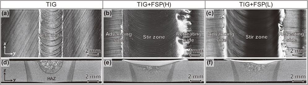
Figure 2 shows the microstructures of the base metal, HAZ at 3 mm away from the TIG weld center, and weld metal at the center acquired from the cross section of the TIG specimen. The base metal consisted of bainitic and polygonal ferrite grains (Fig. 2(a)). The grain size of the HAZ microstructure 3 mm away from the TIG weld center was larger than that at the base metal (Fig. 2(b)), and a similar structure was observed on the opposite side. The weld center consisted of much larger grains than the other positions (Fig. 2(c)).

FSP modified the microstructure at the topmost regions of the weld metal, HAZs, and base metals. Figure 3 shows cross-sectional SEM images obtained from the advancing side, center region, and retreating side beneath the stir zone surface of TIG+FSP(H) and TIG+FSP(L) specimens. The images at the advancing and retreating sides were taken 3 mm away from the FSP center (minus and plus in the direction to the advancing and retreating sides, respectively). FSP at the topmost of the TIG welded beads showed significant grain refinement, but the stir zone microstructure of the TIG+FSP(H) and TIG+FSP(L) specimens differed. Polygonal and bainitic ferrite grains with diameters of about 2–10 µm were observed throughout the stir zone of the TIG+FSP(H) specimen (Fig. 3(a)–(c)). The presence of bainitic ferrite indicates that phase transformations partially occurs during FSP(H). On the other hand, the stir zone produced by FSP(L) exhibited finer microstructure consisting of ferrite grains with average grain size of about 1 µm and cementite precipitates (Fig. 3(d)–(f)). Bainitic ferrite was not formed in the TIG+FSP(L) specimen.

To further characterize the stir zone microstructure produced by FSP(L), EBSD analysis of the stir zone beneath the surface of TIG+FSP(L) specimen was used to obtain grain reference orientation deviation (GROD) maps (Fig. 4). The GROD indicates a misorientation angle between the reference point in the grain and the other points.26–28) The misorientation, which is caused by dislocations due to shear deformation, is associated with residual strain. A color change from white to red corresponds to the increase in the GROD. The black lines in these maps denote high angle boundaries with misorientations in excess of 15°. The stir zone at the advancing side and center exhibited similar ultrafine equiaxed grains with a small average GROD of about 1.1°. On the other hand, elongated ferrite grains with a large average GROD of about 1.5° were observed at the retreating side, indicating the incomplete recovery and recrystallization without any phase transformations during FSP(L).

Figure 5 shows the misorientation angle distributions derived from the EBSD analysis. The total fractions of low angle boundaries at the advancing side and center were estimated to be about a half of that at the retreating side. This suggests that recrystallization occurs at the stir zone throughout the advancing side and center, resulting in almost full relaxation of the mechanically induced plastic strain and formation of the high angle boundaries during FSP(L). By contrast, the peak temperature in the stir zone at the retreating side during FSW/FSP is generally lower than that at the advancing side and center.29,30) Thus, fractions of low and high angle boundaries at the retreating side were higher and lower, respectively, than those at the advancing side and center, indicating that dislocation rearrangement does not complete in the ferrite grains (i.e., recovery and recrystallization does not actively occur at the retreating side).

Figure 6 shows the Vickers hardness distributions measured beneath the surface of TIG, TIG+FSP(H), and TIG+FSP(L) specimens. The weld metal of the TIG specimen exhibited a higher hardness with larger variations than those in the base metal, reflecting the heterogeneous microstructure distribution due to solidification. The TIG specimen had the lowest HAZ hardness near the base metal due to tempering. The microstructural modification by FSP(H) provided a homogeneous hardness distribution, and its average value of about 180 HV in the stir zone were higher than those of the base metal. On the other hand, the average hardness of about 230 HV in the stir zone in the TIG+FSP(L) specimen was significantly higher than that in the TIG+FSP(H) specimen. It should be noted that the peak hardness observed at the retreating side seemed to be associated with the residual strain and low angle boundaries in the elongated ferrite grains.

The residual stress distribution in the stir zone of the TIG+FSP(L) specimens was measured. Figure 7 compares the longitudinal and transverse residual stress distributions on the surface of TIG+FSP(L) specimens with those of TIG and TIG+FSP(H) specimens. The peak tensile residual stress (about 300 MPa) for the TIG specimen was observed near the weld center in both the longitudinal and transverse directions. The tensile residual stresses were balanced by compressive residual stresses in the HAZ around the weld metal. FSP(H) provided a homogeneous residual stress distribution in the stir zone similar to the hardness distribution in Fig. 6. The peak tensile residual stress for the TIG+FSP(H) specimen was lower than that for the TIG specimen. By contrast, FSP(L) provided an asymmetrical distribution of the residual stress with a tool rotational axis. The peak tensile residual stress observed in the stir zone at the retreating side was higher than that at the advancing side. Additionally, it was higher along the longitudinal direction but similar along the transverse direction compared with that in the TIG specimen. FSP(L) provides a higher tensile residual stress than that of FSP(H), especially at the retreating side.

Generally, the literature reports that the residual stress distribution in the stir zone was symmetric with respect to the tool rotational axis.17–20,31–34) This is similar to that in the TIG+FSP(H) specimen, but obviously differs from that observed in the TIG+FSP(L) specimen. The difference in the tendency of the residual stress is the same as those of the microstructure and hardness.
Figure 8 shows the relationship between the transverse residual stress and the average GROD obtained on the stir zone beneath the FSP(L) surface as a function of the positions with respect to the FSP(L) center in the TIG+FSP(L) specimen. The transverse residual stress profile agrees well with that of the average GROD. The peak values were located at a distance of 3 mm from the stir zone center to the retreating side, corresponding to the positions near a plunged probe. Thus, the peak tensile residual stress in the stir zone at the retreating side in the TIG+FSP(L) specimen can be explained by the presence of elongated ferrite grains due to plastic deformation. By contrast, the advancing side seems to have less relation between the transverse residual stress and the average GROD. It is probably associated with the other dominant mechanisms for providing the residual stresses, for example, higher thermal stresses depending on higher peak temperature at the advancing side during FSP,29,30) but the details are not clear.

The bending fatigue performance of those specimens was investigated. Figure 9 shows the relationship between the stress amplitude applied at the weld center and the number of cycles to failure (S-N diagram). Compared to that of the TIG specimen, both FSP(H) and FSP(L) significantly improved the fatigue strength. The values of the stress amplitude at the number of cycles to failure of 2 × 10⁶ cycles (set as the fatigue limit) increased to 300 and 350 MPa (arrows mean “without failure”) in the TIG+FSP(H) and TIG+FSP(L) specimens, respectively. These improvement rates were estimated to be about 20 and 40% compared to that of the TIG specimen (250 MPa). Therefore, both FSPs effectively improve the fatigue strength of TIG welded steels, but the decrease in FSP heat input results in further improvement.

Figure 10 shows the SEM images of the fatigue fracture surfaces obtained at a stress amplitude of 375 MPa. The fractographs consist of fatigue crack propagation and fast fracture regions, in order from the processed surface (in tension during the three-point bending fatigue test). Any fatigue crack propagation zones were not observed at the back side loaded in compression. The fatigue crack initiation sites were found near the center of beach marks observed on the fracture surface. Some fatigue cracks were initiated from the surface and propagated in the weld metal in the TIG specimen (Fig. 10(b)). Fatigue cracks were also initiated at the surface in the TIG+FSP(H) specimens (Fig. 10(d)), and their fracture surfaces consisted of the stir zone and weld metal (Fig. 10(c)). In contrast, the surface position of the stir zone produced by FSP(L) did not become a fatigue crack initiation site. However, the crack was initiated in a side face of the specimen, which was near a spherical inclusion with dark contrast (Fig. 10(f)), and propagated in the stir zone toward the surface (Fig. 10(e)). This suggests that decreasing the FSP heat can increase the hardness due to further grain refinement, which leads to an enhanced resistance to fatigue crack initiation.

To clarify the stir zone position dependence of the fatigue performance caused by the asymmetrical microstructure and residual stress distribution with respect to the tool rotational axis in the stir zone produced by FSP(L), a three-point bending load was applied to each position of the advancing and retreating sides as well as the center position of the stir zone. The loading position was set about 3 mm away from the stir zone center to the advancing or retreating sides. Figure 11 shows fatigue testing results of the TIG+FSP(L) specimens loaded at the advancing and retreating sides (hereafter referred to as advancing-side or retreating-side specimens, respectively) plotted on the S-N diagram, together with those loaded at the center (Fig. 9) for comparison. Unfortunately, fatigue crack initiation occurred at a side face in all the specimens due to the hard stir zone, similar to the specimen loaded at the stir zone center shown in Figs. 10(e) and (f). Therefore, the S-N curves of the advancing-side and retreating-side specimens did not exhibit obvious differences. These observations suggest that the effects of the asymmetrical microstructure and residual stress distributions in the stir zone cannot be seen in the S-N curves. Both the advancing-side and retreating-side specimens have slightly lower fatigue strength in comparison to those loaded at the stir zone center. This difference can be attributed to the smaller stir zone thickness. On the other hand, the fatigue strength obtained in the specimens loaded at any positions in the stir zone produced by FSP(L) was higher than those loaded at the stir zone center produced by FSP(H). It should be noted that the prevention of crack initiation due to the hardness increase in the stir zone is preferable to decreasing the tensile residual stress to improve fatigue strength. Thus, the additional grain refinement upon decreasing the FSP heat input can be an effective way to greatly improve the fatigue strength of steel welds.

4. Conclusions
The effects of the microstructure and residual stress on the fatigue strength when using low-heat input FSP (FSP(L)) on TIG welded low carbon steel plates (SS400) were investigated and compared with those of conventional FSP (FSP(H)). Reducing the FSP heat input enhances the grain refinement and improves the fatigue strength, although the tensile residual stresses due to the incomplete recovery and recrystallization are induced locally in the stir zone. The important findings can be summarized as:
-
(1)
FSP refined the weld microstructure. The ferrite grain sizes in the stir zone produced by FSP(H) and FSP(L) were reduced to about 2–10 and 1 µm, respectively. The microstructural modifications due to FSP(L) significantly increased the surface hardness to about 230 HV, while the stir zone produced by FSP(H) exhibited the average hardness (about 180 HV) similar to the minimum value in the weld metal of the TIG specimen.
-
(2)
FSP(H) provides homogeneous tensile residual stress distributions in the stir zone, but decreased the maximum value in the weld metal produced by TIG welding. By contrast, that in the stir zone produced by FSP(L) possessed an asymmetrical distribution with respect to the tool rotational axis. The peak tensile residual stress was located in the stir zone at the retreating side, associated with the formation of elongated grains having high residual strain.
-
(3)
The bending fatigue strength of the TIG+FSP(H) and TIG+FSP(L) specimens was higher than that of the TIG specimens at all cycles. The estimated improvement ratio due to FSP(L) was twice as large as that due to FSP(H). The ultrafine-grained structure and its associated high hardness in the stir zone produced by FSP(L) helped prevent the fatigue crack initiation at the stir zone surface.
-
(4)
The fatigue strength obtained in the specimens loaded at the advancing and retreating sides in the stir zone produced by FSP(L) was also higher than those loaded at the stir zone center produced by FSP(H), while the fatigue crack initiation occurred at the side face for all the TIG+FSP(L) specimens.
REFERENCES
- 1) R.S. Mishra and Z.Y. Ma: Mater. Sci. Eng. R 50 (2005) 1–78.
- 2) I. Charit and R.S. Mishra: Mater. Sci. Eng. A 359 (2003) 290–296.
- 3) Y.S. Sato, P. Arkom, H. Kokawa, T.W. Nelson and R.J. Steel: Mater. Sci. Eng. A 477 (2008) 250–258.
- 4) D. Yadav and R. Bauri: Mater. Sci. Eng. A 539 (2012) 85–92.
- 5) D.M. Sekban, S.M. Aktarer, P. Xue, Z.Y. Ma and G. Purcek: Mater. Sci. Eng. A 672 (2016) 40–48.
- 6) W.-B. Lee, J.-W. Kim, Y.-M. Yeon and S.-B. Jung: Mater. Trans. 44 (2003) 917–923.
- 7) Y.-J. Kwon, I. Shigematsu and N. Saito: Mater. Trans. 44 (2003) 1343–1350.
- 8) Y.-J. Kwon, I. Shigematsu and N. Saito: Trans. 45 (2004) 2304–2311.
- 9) H.S. Park, T. Kimura, T. Murakami, Y. Nagano, K. Nakata and M. Ushio: Mater. Sci. Eng. A 371 (2004) 160–169.
- 10) Y. Zhang, Y.S. Sato, H. Kokawa, S.H.C. Park and S. Hirano: Mater. Sci. Eng. A 485 (2008) 448–455.
- 11) L. Yu, K. Nakata and J. Liao: Mater. Trans. 50 (2009) 2378–2383.
- 12) H. Fujii, Y. Sun, H. Kato and K. Nakata: Mater. Sci. Eng. A 527 (2010) 3386–3391.
- 13) Y.F. Sun and H. Fujii: Mater. Sci. Eng. A 527 (2010) 6879–6886.
- 14) L. Cui, H. Fujii, N. Tsuji and K. Nogi: Scr. Mater. 56 (2007) 637–640.
- 15) Y.D. Chung, H. Fujii, R. Ueji and N. Tsuji: Scr. Mater. 63 (2010) 223–226.
- 16) S.A. Khodir, Y. Morisada, R. Ueji and H. Fujii: Mater. Sci. Eng. A 558 (2012) 572–578.
- 17) H. Lombard, D.G. Hattingh, A. Steuwer and M.N. James: Mater. Sci. Eng. A 501 (2009) 119–124.
- 18) A. Steuwer, S.J. Barnes, J. Altenkirch, R. Johnson and P.J. Withers: Metall. Mater. Trans. A 43 (2012) 2356–2365.
- 19) G. Pouget and A.P. Reynolds: Int. J. Fatigue 30 (2008) 463–472.
- 20) L. Fratini, S. Pasta and A.P. Reynolds: Int. J. Fatigue 31 (2009) 495–500.
- 21) T.H. Tra, M. Okazaki and K. Suzuki: Int. J. Fatigue 43 (2012) 23–29.
- 22) K. Ito, T. Okuda, R. Ueji, H. Fujii and C. Shiga: Mater. Des. 61 (2014) 275–280.
- 23) H. Yamamoto and K. Ito: Mater. Sci. Appl. 9 (2018) 625–636.
- 24) H. Yamamoto, Y. Danno, K. Ito, Y. Mikami, K. Kohama and H. Fujii: Weld. Lett. 36 (2018) 1WL–4WL.
- 25) H. Yamamoto, Y. Danno, K. Ito, Y. Mikami and H. Fujii: Mater. Des. 160 (2018) 1019–1028.
- 26) C. Schayes, J. Bouquerel, J.-B. Vogt, F. Palleschi and S. Zaefferer: Mater. Charact. 115 (2016) 61–70.
- 27) M.N. Gussev and K.J. Leonard: J. Nucl. Mater. 517 (2019) 45–56.
- 28) S.-S. Rui, L.-S. Niu, H.-J. Shi, S. Wei and C.C. Tasan: J. Mech. Phys. Solids 133 (2019) 103709.
- 29) R. Nandan, G.G. Roy, T.J. Lienert and T. Debroy: Acta Mater. 55 (2007) 883–895.
- 30) S. Swaminathan, K. Oh-ishi, A.P. Zhilyaev, C.B. Fuller, B. London, M.W. Mahoney and T.R. Mcnelley: Metall. Mater. Trans. A 41 (2010) 631–640.
- 31) A.P. Reynolds, W. Tang, T. Gnäupel-Herold and H. Prask: Scr. Mater. 48 (2003) 1289–1294.
- 32) W. Woo, H. Choo, M.B. Prime, Z. Feng and B. Clausen: Acta Mater. 56 (2008) 1701–1711.
- 33) A. Steuwer, D.G. Hattingh, M.N. James, U. Singh and T. Buslaps: Sci. Technol. Weld. Join. 17 (2012) 525–533.
- 34) J.W. Sowards, T. Gnäupel-Herold, J.D. McColskey, V.F. Pereira and A.J. Ramirez: Mater. Des. 88 (2015) 632–642.